1
BU/RB MIMO Quick Installation Guide
•
•
•
No.13 wrench
Isolation materials. Use high quality cold shrink for the antenna connectors
Grounding cable with at least 18 AWG gauge and with a closed loop (lug) terminal crimped to the ground cable
Equipment Location Guidelines
The BU/RB unit can be installed on straight or angled poles (±45° from upward position) and on a flat surface, such as walls.
Each unit package includes a tilt bracket that allows pole or wall mount installation with up/down tilt of +7.5° to -10°, and rotation
of ±45°. Select the orientation and installation mode according to the Radio Planning and Site Survey recommendations.
The BU/RB unit (depending on the model) is offered with either integrated antenna or external antenna. The following table
details the options for each model.
Follow the installation guidelines provided with the external antennas.
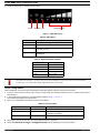
Table 1: Antenna Configuration Options
Model
Integrated Antenna
External Antenna
BU/RB-B350-5X
23 dBi 8 deg, dual polarization
N/A.
BU/RB-B350D-5X
N/A
Note: The two antenna connectors are not operational.
•
•
High gain dish: 28 dBi 2” parabolic dish, dual
polarization
Low gain antenna: 23 dBi dual polarization
Note: Only two of the antenna connectors are
operational.
Select the optimal locations for the equipment using the following guidelines:
•
•
•
•
•
The outdoor unit can be either pole or wall mounted. Its location should enable easy access to the unit for installation and
testing.
The higher the placement of the antenna, the better the achievable link quality.
ODU units with a detached antenna (D model) should be installed as close as possible to the antenna (to ensure that the
antenna's characteristics are not affected by the ODU, the distance must be higher than 10 cm).
The ODU with its integrated antenna (or the detached antenna) should be installed to provide a direct, or near line of sight
with the antenna on the other side.
The indoor equipment should be installed as close as possible to the location where the indoor-to-outdoor cable enters the
building. The location of the indoor equipment should take into account its connection to a power outlet and the CPE.
Outdoor Unit Installation
Mount the ODU unit on a 1"-4" pole using the supplied kit:
1
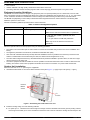
Assemble the tilt bracket on the unit and fasten the M8 screws (see Figure 1). Apply torque of 80 [Lib*In] = 9 [N*m].
Holes for
M8x20
screws
Tilt
Bracket
Figure 1: Assembling the Tilt Bracket on the Unit
2
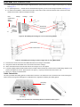
Install the carriage using one of the following methods:
»
For poles up to 4” - Thread the four rods through the carriage. Insert the threaded rods with the grooves pointing outward,
as these grooves enable you to use a screwdriver to fasten the rods to the unit. Attach the carriage and the clamps to the
P/N 215998
-2-
March 2012