1
BU/RB MIMO Quick Installation Guide
Aligning the ODU
For optimal alignment of the internal antenna, it is recommended to use the Continuous SNR Display option.
Antenna alignment using the SNR bar display or the Continuous SNR Display is possible only after the RB is
associated with a BU. Both units must be operational and configured with the correct basic parameters (see
above). Otherwise, the two units will not be able to synchronize with each other. As the SNR measurement is
performed on received frames, it is recommended to generate traffic in the wireless link (e.g. by a continuous
ping).
1
2
3
4
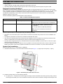
Point the antenna of the BU (integrated into the front side of the ODU unit, or detached) towards the direction of the RB, and
vice versa. Take into account the direction in both horizontal and vertical planes. See note below regarding using a compass
for intial alignment.
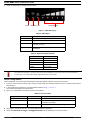
Verify that the power indication of the units is On.
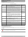
Verify that the Wireless LED of the ODUs is on, indicating wireless link connectivity. If the Wireless LED is off, check that the
basic parameters (see Table 6) are correctly configured. Proper wireless connectivity depends also on wireless link
conditions and correct orientation of the antennas.
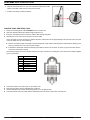
Rotate/tilt the antenna of the RB-ODU until the maximum SNR reading is achieved, where at least 1 green LED is on. If you
encounter prolonged difficulty in illuminating the minimum required number of green LEDs, try to improve the reception
quality by placing the antenna at a higher point or in an alternate location.
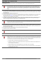
All LEDs of the SNR bar display are on at SNR level of 25 dB. In many links a better link quality is expected. For
links with a better quality you should always use the Continuous SNR Display option via Telnet (you may also
connect a PC to the unit via the PoE Out connector).
5
6
7
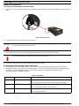
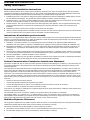
Ensure that the front of the antenna is always facing the location of the BU. However, in certain conditions, such as when the
line of site to the BU is hampered, better reception may be achieved using a reflected signal. In this case, the antenna is not
always directed toward the BU.
After achieving maximum SNR reading, secure the unit/antenna firmly to the pole.
Repeat the process at the side of the BU.
If applicable, verify that the achieved SNR is similar to expected SNR according to Radio Network Planning.
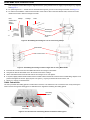
Aligning the Antenna Using a Compass:
Aligning the antenna using a compass takes into account the original azimuth and calculates a new azimuth that
is shifted by ±90° from the actually required azimuth. The idea is to align the outer frame of the antenna so that
it is in line with the new azimuth, which will achieve higher accuracy of initial alignment.
P/N 215998
1
Point the antenna of towards the general direction of the other unit.
2
Depending on whether you are looking from the left or the right side of the antenna, add or subtract 90° to/
from the original antenna azimuth.
3
Identify a reference point on the landscape that is in the direction of the new heading.
4
Using the compass, align the outer frame of the antenna to the newly calculated azimuth, or to the reference
point identified in point 3 above.
-9-
March 2012