1
Hytec Electronics Ltd
MCS8522/UTM/3.0
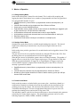
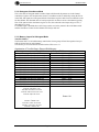
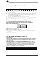
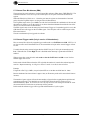
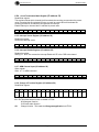
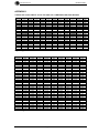
6.2.1 Preset Counting and Shadow Registers (I/O Address 0-31)
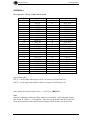
Counter Registers 0 to 15 are held in the I/O space of the IP scaler card.
The counter registers may be preloaded and read at addresses 00-1E (even) for the least
significant words
D15
S15
D14
S14
D13
S13
D12
S12
D11
S11
D10
S10
D09
S9
D08
S8
D07
S7
D06
S6
D05
S5
D04
S4
D03
S3
D02
S2
D01
S1
D00
S0
D23
S23
D22
S22
D21
S21
D20
S20
D19
S19
D18
S18
D17
S17
D16
S16
and 01-1F(odd) for the most significant words.
D31
S31
D30
S30
D29
S29
D28
S28
D27
S27
D26
S26
D25
S25
D24
S24
Important Note When reading the counters with the Scalers enable, both the low and high
word of the counter are latched in to the shadow register when the Least significant word is
read and not when the most significant word read. This will ensure the correct 32 bit count
word is read.
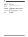
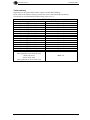
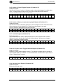
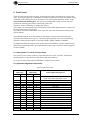
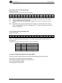
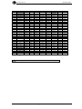
6.2.2 Control & Status Register (CSR I/O Address 48)
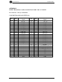
Read/write register
Control and Status bits.
D15
D14
TS1
D13
TS0
D12
D11
D10
D09
D08
D07
FF
D06
CT
D05
ST
D04
ER
D03
ET
D02
IE
D01
R
D00
IRQ
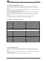
IRQ Interrupt Request. Ready, generated at the end of the programmed number of cycles
or when preset value reached in preset Scaler mode. (Read only).
R
Reset - writing a 1 to this bit resets all the counters and memory to zero. This bit also
indicates when clear memory routine has started='1' and finished='0' for both
hardware and software memory clears.
IE
Interrupt enable enables IRQ to generate interrupt when set to a ‘1’.
ET Enable Hardware TRIGGER IN from Transition board to initiate each acquisition cycle.
ER Enable Reset . Enables external hardware reset to clear scalers and memory.
ST Software TRIGGER enables the counters.
CT This clears the trigger and stops the counters.
FF Finish flag set when a counter(s) (as shown in Preset Hit reg) reach its/there preset
value. This flag is cleared when the Preset Hit registers is cleared. (read only).
TSx Selects a “00”=25MHz, “01”=50MHz, “10”=100MHz or “11”=200MHz test input to
counters.
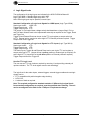
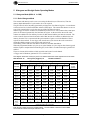
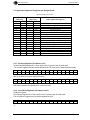
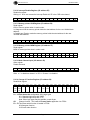
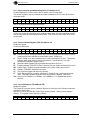
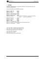
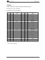
6.2.3 Preset Hit Register (I/O address 52)
Read/write register.
The Preset Hit from each scaler is latched. When a bit or bits are set it indicates scaler has
reached its preset value.
Writing a ‘1 to a bit will clear the Preset Hit bit for that channel. Writing a zero changes
nothing. This register is also cleared by a Reset.
D15
O15
D14
O14
D13
O13
D12
O12
D11
O11
D10
O10
D09
O9
D08
O8
D07
O7
Page 21
D06
O6
D05
O5
D04
O4
D03
O3
D02
O2
D01
O1
D00
O0