1
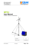
GeomSpace User Manual
Alexandru Popa & Team
email: [email protected]
http://sourceforge.net/projects/geomspace/
version 0.12
1
1
Why GeomSpace?
GeomSpace is interactive geometry program for Euclidean and non–Euclidean
spaces. It is unique piece of software that:
• Gives you feeling of space, not of space model;
• Has no restriction on space dimension;
• Performs equally well for spaces: Euclidean, Riemann, Bolyai–Lobachevsky,
Galilean (including curved ones), Minkowskii (including curved ones) and
other homogeneous spaces. Actually, GeomSpace uses the same code for
all them;
• Uses native OpenGL calls not only for Euclidean–like motions, but for all
possible motions.
Also, advantages of GeomSpace over similar interactive geometry programs
include:
• Small size;
• Tiny and/or standard dependence libraries (FLTK );
• Really cross–platform (compiles without modification of the code for Linux,
Windows, OS X, FreeBSD and Solaris, including 32 and 64 bit versions).
Hire is full list of supported platforms with some recomandations:
linux64 is prepared for modern Linux system installed as amd64 port. It
should run with most distributions.
linux32 is prepared either for older computers with Linux system installed, or
for Linux i386 port installation. In many cases this version will also run
in Linux amd64 environment (with support of 32 bit able graphic driver
and libraries).
windows64 is prepared with support of .NET runtime and is recomanded for
Windows Vista, Windows 7 and above.
windows32 is optimized for Windows XP, but is able to run also in Windows
Vista and above.
osx is prepared as “fat binary” sutable for OS X 32 and 64 bit versions. It
should run on Mac OS X Leopard and above.
freebsd64 is compiled for FreeBSD installed as amd64 port on modern computers. It will also run on other FreeBSD–based systems, e.g. PC-BSD.
freebsd32 is compiled for older computers or for i386 port of FreeBSD system.
solaris. Because of Solaris architecture, there is no different 32 / 64 versions
of GeomSpace compiled for it. One “universal” binary will run on Oracle Solaris 10 and above, OpenSolaris, OpenIndiana and Solaris–based
systems.
Enjoy using GeomSpace!
2
2
System Requirements and Limitations
GeomSpace makes use of 3D accelerated graphics hardware. It is the case
of many modern computers. GeomSpace will also run with software simulated
3D acceleration, however it will dramatically drop its performance.
On all supported platforms GeomSpace should run out of the box. The
application is really light, it consumes under 20 MB of memory in full load
(with 3D accelerated graphics adapter).
OS X version starts localized only from the terminal. In order to start
GeomSpace localized, start Terminal.app and issue:
open /path/to/GeomSpace.app
(change “/path/to” to actual path where GeomSpace resides).
Windows version should work out of the box in most cases. For better experience of using it, please keep executable, documentation and localization files in
ASCII-only folders (including whole path). The standard location “C:\Program
Files\GeomSpace” is good. This limitation doesn’t affect model locations.
3
Installation and uninstallation
GeomSpace has no installation program yet. Fresh downloaded and unarchived program will run properly from the folder where it is unarchived. If you
want to “install” it by hand, use the following paths (you may need administrator’s privileges):
Linux/FreeBSD/Solaris/UNIX. You should be familiar with “<prefix>”
folder. It may be /usr, /usr/local, /opt, /local, etc. Copy GeomSpace
to <prefix>/bin, i18n, doc and models folders to <prefix>/share/GeomSpace folder (of course, you can keep the models where you want).
Windows. Copy GeomSpace.exe with i18n and doc folders to C:\Program
Files\GeomSpace. You may keep models where you want, but it is good
idea to keep them together with the program.
OS X. Create folder /Programs/GeomSpace and put here GeomSpace.app
with doc and models folders (feel free to keep the models in different place).
In order to complete installation, add a shortcut to GeomSpace in start
menu, desktop or taskbar using system provided mechanism. Also, register
.gmsp file format by right click on some .gmsp file, choose Open with item
from popup menu and browse to GeomSpace as program that understands this
format.
In order to manually “uninstall” GeomSpace, remove all its files. Please
note that GeomSpace creates resource file: in Windows Vista and above —
%LOCALAPPDATA%\.geomspace\geomspace.rc, in Windows XP — %APPDATA%\.geomspace\geomspace.rc and /.geomspace/geomspace.rc in all other
systems for each system user. You may want to remove also these folders/files.
3
Figure 1: GeomSpace main window
4
Using GeomSpace
You can start GeomSpace in several ways:
• By clicking on GeomSpace executable. GeomSpace starts with no space
selected.
• By clicking on .gmsp model (the first time you need to associate this
file format with the program that reads it). GeomSpace starts with corresponding model opened. You can also select several models and open
them in GeomSpace. Each model opens in separate window (OS X will
open them one after another in the same window).
• From the command line. In this case you can provide as arguments any
number of .gmsp models. In OS X you should open the Terminal application and type:
/path/to/GeomSpace.app/Contents/MacOS/GeomSpace <model1>.gmsp
<model2>.gmsp ...
You can also pass arguments to FLTK (window position, geometry or
color). On unix–like systems you can start different instances of GeomSpace in different languages by setting environment variable LANG
between launches.
In main window (Figure 1) space specification (and not file name) is shown
in the titlebar (or a message about no space selected). At the top of window
you can find menubar with all functions. The right part contains toolbar with
4
common function buttons. After choosing some function, a corresponding dialog apears. The left side of window is reserved for space geometry and user
interaction (keyboard and mouse). You can interact with geometry from the
main window when some dialog is open. Sometimes it is very usefull.
Using GeomSpace you can:
• Create a space by specification,
• Construct geometric model in space,
• View constructed model from any position navigating in space with mouse
and/or keyboard,
• Edit constructed model by adding, removing or moving some its parts,
• Do different calculus on you model and get the result — find out coordinates, basis vectors, distances and angles.
• Exchange created models in .gmsp files.
5
Getting Started
The easiest way to learn GeomSpace is to open an existing model. GeomSpace uses .gmsp files that describe a space with gemetry model in it. The
file however doesn’t contain camera position and orientation, because it is not
the property of space or model. You can find several models on project website.
You can configure your system to open them with GeomSpace by right–clicking
on a .gmsp file, select Open with option and select GeomSpace as program that
reads them.
You can open and save these models by pressing Open and Save buttons
from Space group. A file browser appears allowing you to select a model.
Used Projection. For dimensions 1 or 2 no projection is performed. In this
case OX1 axis is oriented left-to-rigth and OX2 is bottom-up. For dimension
3 the perspective projection is performed by OpenGL runtime. User is always
positioned in the center of model. OX3 axis direction is toward the camera1 .
For dimensions greater then 3, first parallel projection is (programmatically)
performed to 3–dimensional plane X1 X2 X3 and then perspective projection is
performed by OpenGL runtime. Axes OXn , n ≥ 3 have no graphic representation.
User Interaction. Once you opened a model, you can change camera position
/ orientation regarding the space in the following way:
• Use arrow keys ← , → , ↑ , ↓ and − or + keys to move yourself
through the space (for 2–dimensional spaces the last two keys rotate space
around the center).
• Use left mouse drag to move the space along you and right mouse drag to
orbit the space around you.
1 This
behavior will be changed in future.
5
• Use Shift + left mouse drag to move yourself in the space and Shift +
right mouse drag to orbit yourself in the space.
• Use mouse wheel to move forward / backward (if space dimension is greater
then 2) or rotate space (2–dimensional only) around the center.
• Use P key to show camera orientation matrix, O to show camera state
matrix (orientation “orthogonalness”) and R to reset camera orientation
to default.
• Use N key to show / hide unused points and point names.
• Use H or F1 keys to display this help.
If you want to see the model from different angles, you need to perform a
range of translations and rotations in opposite directions, as if you are walking
around the model. So, press the left button and move the mouse in one direction,
then press the right button and move the mouse in the opposite direction.
Repeat this several times.
6
Space Creation
Figure 2: Space Dialog
You can construct new space by choosing its specification and color. When
you press New button from Space group, the Space Dialog (Figure 2) appears.
Space Dialog allows you to choose the dimension and, after pressing Change
button, space specification as number of characteristics k1 , k2 , ..., kn , where
• k1 is the characteristic of distances,
• k2 is the characteristic of plane angles,
• k3 is the characteristic of dihedral angles between 2–dimensional planes,
• ...,
• kn is the characteristic of dihedral angles between (n − 1)–dimensional
planes.
Each characteristic may have one of the following values:
• 1 — for elliptic characteristic,
6
Start
Euclidean space {0,1,...,1}
Elliptic spce {1,1,...,1}
Hyperbolic space {-1,1,...,1}
Minkowskii space {0,-1,1,1)
for timelike geometry or
{0,1,1,-1} for spacelike
geometry
m = maximal number of general
situated points or minimal number
of verteces that form a positivevolume figure (simplex)
Dimension d = m - 1
i=0
1-dimensional planes are lines
0-dimensional planes are points
Are all i-dimensional
planes congruend?
No
Yes
Yes
Is measure between 2
i-dimensional planes bounded
No
No
Is measure between 2
i-dimensional planes scalable
Yes
ki = 0
ki = -1
Yes
i=i+1
ki = 1
i<n
No
This geometry is inconsistent.
It is possible to use the model,
but the terminology may differ
d, ki, 1<=i<=n
Figure 3: Algorithm to determine space specification
7
• 0 — for parabolic characteristic and
• −1 — for hyperbolic characteristic.
If you use Euclidean, elliptic or hyperbolic (Bolyai-Lobachevsky) space of
dimension n, use the following specification {k1 , k2 , ..., kn }:
{0, 1, ..., 1} — for Euclidean space,
{1, 1, ..., 1} — for elliptic space and
{−1, 1, ..., 1} — for hyperbolic space.
If you plan to use another space use the algorithm presented in Figure 3 to
determine its specification. For more information about what space specification
is about and how to find it, please refer to the theory behind GeomSpace:
“Uniform Theory of Geometric Spaces” (presented in popular manner)
or “Analytic Geometry of Homogeneous Spaces” (presented in rigurous
mathematical manner), both available at the project website.
Default values for space specification in Space Dialog is taken from previous
space (or dimension 0 with no specification if no space was present). So you can
clear the space just by pressing New button and accepting default values.
Choosing the Color. Beside space dimension and specification you can choose
space background color. Space Dialog, as well as other dialogs, uses a simple
color chooser for geometry elements, presented at Figure 2, at left picture in red
border.
This element acts as toggle button. Four spinners for color components
open/hide on its press. You can choose R (red), G (green), B (blue) and A
(alpha, opacity) color components in range 0 ... 255. While modifying the color
components, Color Chooser button changes its color to reflect the current color
selection. Its central part shows color with opacity and outer part uses solid
color in order to figure out the opacity by contrast.
7
Constructing Geometry
When the space is chosen, you can construct different figures in it. Construct Dialog (Figure 4) opens by pressing Add button from Construct group.
This dialog contains two tabs: Points — for construction of points by their
coordinates and Faces — for construction of faces by specifying their points.
Constructing a point is as simple as choosing its coordinates in Lineal Chooser
(presented in Figure 4, at left picture, green bordered) and pressing Add point
button (see below how to use Lineal Chooser). Each point gets the unique name,
containing capital letters and digits, starting with A0. Each new point name
have the letter part as previous point and the number part increased by 1. So
after A0 follow A1, A2 and so on. If you press New group button, the next
point name will be formed by the next letter followed by 0. In this case, after
A2 follows B0 point name (after Z point group follows AA, AB and so on).
When new space is chosen, the point names are reset.
Point dots and names are visible in space only when some dialog is open.
Once the dialog is closed, dots and names are hidden. You can toggle points
visibility by pressing N key.
Points don’t make part of space geometry and normally aren’t shown (when
all dialogs are closed). In order to construct a true geometric point with the
8
Figure 4: Construct Dialog. Point construct tab (left) and face construct tab
(right)
current color, a one–point face should be constructed. It is automatically constructed with the point if Also face checkbox is checked.
Most faces are constructed from Faces tab using Construct Chooser (presented in Figure 4, at right picture, blue bordered; see below how to use it).
When you are sure that face name shown in Face: output is correct, you can
construct it with the current color by pressing Add face button.
Points Creation with Lineal Chooser. Lineal Chooser allows you to select
normalized point coordinates (column) as well as generalized orthogonal motion
(square) matrix and orthonormal basis of a lineal (rectangular matrix) using
homogeneous coordinates.
In case of points, the origin has coordinates (1 : 0 : ... : 0). In order to
change shown coordinates or matrix you need to select two radio boxes. Then
Measure spinner becomes active and you can change its value. If you select 0
and i radio boxes, measure means distance of translation along OXi axis. If
you check i and j checkbox, measure means angle of rotation in plane Xi OXj
around the origin from lower to higher axis index.
You can modify the measure value by hand, but in this case the matrix
coordinates will not be refreshed automatically. In order to force it to refresh,
you can select / unselect some radio box, or click on Points tab title. The Reset
button resets coordonate matrix to initial value.
Constructing Faces with Construct Chooser. Construct Chooser allows
you to select a valid face name. In Point(s) input you can specify point name(s)
which this face will contain. Points order doesn’t matter. You can write them
toghether or separated by a space or any other character(s), different from
capital letter and digit. After pressing + Points button all valid points in
correct order will be added to Face output, so you can see the face name before
using it. If you want to remove some point(s) from face name, you can write its
name (their names) in Point(s) input and press - Points button.
A face can have the number of points equals at most to the space dimension
and at most 3. If Point(s) editbox contain more valid points then that, only
the first (in specified order) points will enter in the face.
9
8
Removing Faces
You can remove existing faces by using Remove Dialog (Figure 5), which
opens by pressing Remove button from Construct group. All you need is to
select the face or face set to remove with Face Chooser (presented in Figure 5
in brown border; see below how to use it) and press Remove selected button.
Please note, that removing faces process is resources consuming. It is better
to remove once a large amount of faces then to remove them one by one. It
isn’t possible to remove points as they are not part of geometry. If you want
to remove all faces and all points, just construct new space by pressing New
button from Space group and accept default values.
Figure 5: Remove Dialog
Choosing Face Set. You can choose a set of existing faces using Face Chooser.
The Pattern input accepts name patterns. A name pattern is a set of point
names. Their order doesn’t matter. You can write them toghether or separated
by a space or any other character(s), different from capital letter and digit.
The + Pattern button adds to the current selection (listed in upper part
of Face Chooser) all existing in space faces that match the pattern by selected
match criteria. The - Pattern button removes from the current selection all
faces that match the pattern by selected (may be different) match criteria.
There are 4 different match criterias.
Exact match applies only when the face name is the same (regardless the
point order) as the pattern.
Pattern subset applies to all faces with names that contain the whole pattern.
Pattern superset applies to all faces with names contained in the pattern.
Pattern intersects applies to all faces with names that contain at least one
point of the pattern.
In order to select all existing faces choose Pattern subset match criteria and
leave Pattern blank, after that press + Pattern button. If you want to clear
selected faces list, choose Pattern subset match criteria and leave Pattern blank,
after that press - Pattern button.
10
9
Transforming Geometry
Transform feature is not the same as camera motion achieved by mouse and
keyboard interaction. Camera motion changes observer’s position and orientation in space (all motions are around observer), but it doesn’t change figures
position. Camera motion is done in projected space model, so it is limited to
at most 3 dimensional motions (the maximum OpenGL dimension). At the
other hand, transform keeps the camera position and orientation and actually
changes figure points coordinates (all motions are around origin). All possible
motions are available via transform feature. It is very usefull when you play
with spaces of dimension more then 3. You can use camera motion and figure
motion simultaneously. However, please note that while camera motion is done
in specialized graphics hardware (GPU + graphic memory), figure motion is
done in main hardware (CPU + main memory). It is very probable that motion
of large figures is less efficient then camera motion.
Figure 6: Transform Dialog
Transform Dialog (Figure 6) allows you to copy or move selected piece of
geometry. First, you have to select figures you want to copy / move using
Face Chooser (see Figure 6, left). If you plan to copy selected figures, check
Keep original chechbox. If you want to move them, leave it unchecked. When
you are sure figures are selected correctly, press Start button. Face Chooser
becomes inactive and Lineal Chooser becomes active, so you are able to select
the transform (Figure 6, right). While transform matrix is changing, the current
transform is immediatly applied to selected figures and you can see the resulting
geometry.
While selected figures are transformed, you can observe that original points
stand on their positions, even if they are not associated with a face. Same point
names are used also in transformed figure. So you can watch how the current
transform changes their position even if you are opted to move the figure. If
you want to reset figure to its original position, you can press Reset button.
11
When you finish transforming, press Stop button. Once it is pressed, face
selection is cleared and transformed points get new names in order to keep them
unique. The Close button in Transform Dialog is disabled until you stop the
transform. If you close Transform Dialog (by pressing Esc key or × button
from Transform Dialog), the transform stops before dialog closes.
You can start several transform actions simultaneously. Sometimes it is
usefull. The only idea to keep in mind is that Transform Dialog grabs mobile
figure parts so they are not available for selection in the second dialog and so
on.
10
Calculating Bases
You can find homogeneous coordinates of some point or orthonormal basis
of some lineal in canonic form by pressing Basis button from Calculate group.
Basis Dialog appears (Figure 7). In this dialog you can choose a lineal in
Construct Chooser. It may form or may not form an existing face. After that,
press Get info button. The following info will be shown: lineal name, lineal
specification (specification of space defined by lineal) and lineal orthonormal
basis. You can repeat this procedure with another lineal. In case lineal contain
one point, its homogeneous coordinates will be shown. Its specification is void
since point is space of dimension zero.
Figure 7: Basis Dialog
11
Calculating Distances and Angles
Using measure feature, you can find the distance between two points or
a point and a lineal, as well as angle between two lineals (in case lineals are
intersected) or distance between them (in case lineals are not intersected). GeomSpace uses unusual Measure Dialog due to the fact different spaces have different configurations of mutual positions of lineals. GeomSpace measure gives
only relevant informations and all these informations. They include measure
characteristic (showing what kind of measure it is) and measure value (direct
and complementary). It is important to know both direct and complementary
values because for some measure characteristics one of them can be infinite or
unmeasurable (for details, please refer to theory behind GeomSpace: “Uniform
12
Theory of Geometric Spaces” or “Analytic Geometry of Homogeneous
Spaces”, available at project cite).
Figure 8: Measure Dialog
In order to explane what means relevant and non–relevant informations,
consider two lines in Euclidean plane. In case they are intersected, the most
relevant information is the angle between them (elliptic measure characteristic).
In case they are parallel, the most relevant information is distance between them
(parabolic measure characteristic). If these two lines are in elliptic plane, there
is no difference between distances and angles as all measures have elliptic characteristic. If these two lines are in hyperbolic plane, they can be intersected
(elliptic measure characteristic), parallel (parabolic measure characteristic) or
divergent (hyperbolic measure characteristic). All these cases are properly handled by measure feature.
You can open Measure Dialog (Figure 8) by pressing Measure button from
Calculate group. Using Construct Chooser, you can fill out Lineal 1: and
Lineal 2: static texts by pressing Lineal 1, respective Lineal 2 buttons. They
may form or may not form existing faces. After that, press Calculate button to
find relevant measure characteristic and value between lineals.
12
Configuration and sessions
GeomSpace keeps track on what folders were visited last time for reading
models from or writing models to. If it is just downloaded or properly installed,
GeomSpace is able to locate localization data and documentation. In case the
program fails to find them, you can point out the folders for localization and for
documentation using Settings Dialog (available from Tools → Settings menu).
Please take into consideration that if GeomSpace failed to find localization
due to missing information and you provide such information (supposing the
localization file for your language exists), you have to restart the program in
order to make effect.
Each time before closing GeomSpace saves its configuration to disk. When
it starts, GeomSpace reads or creates its configuration.
13