1
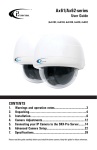
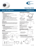
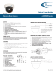
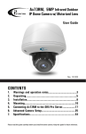
Ax68R/Ax78R
360-degree IR camera
User Guide
Rev. 150505
CONTENTS
1. Warnings and operation notes..........................................3
2.Unpacking....................................................................5
3.Installation.....................................................................6
4.Mounting.........................................................................10
5. Connecting Ax68R/78R to the SRX-Pro Server...............17
Please read this guide carefully before you install the dome camera. Keep this guide for future reference.
Ax68/Ax78R-series User Guide
COPYRIGHT © 2015 by i3 International, Inc. All rights reserved.
No part of this manual may be reproduced or transmitted in any form or by any
means, electronic or mechanical, including but not limited to, photocopying,
recording, or by any information storage or retrieval system, without the prior
written permission of the copyright owner and the publisher.
Annexxus is a registered trademark of i3 International Inc.
Table of Contents
1. Warnings and operation notes
2.Unpacking
3.Installation
4. Mounting
5. Connecting Ax68R/Ax78R to the SRX-Pro Server
Disclaimer
This quick start guide is provided as is, without warranty of any kind, expressed or
implied, including but not limited to performance, merchantability, or fitness for any
particular purpose. Neither i3 International Inc. nor its dealers or distributors shall be
liable to any person or entity with respect to any liability, loss, or damage, caused or
alleged to have been caused directly or indirectly by this information.
Furthermore, i3 International Inc. reserves the right to revise this publication, and to
make changes to the content at any time, without notice.
FCC
This device complies with part 15 of the FCC Rules. Operation is subject to the
following two conditions: (1) This device may not cause harmful interference, and (2)
this device must accept any interference received, including interference that may
cause undesired operation.
Address:
i3 International Inc.
780 Birchmount Road, Unit 16
Scarborough, ON M1K 5H4
Canada
i3-TRNG-CAMS-68R_78R.indd
Contact us:
Tech Support: 1.877.877.7241
Email. [email protected]
Web Site: www.i3international.com
2
Rev. 150505
1. Warnings and operation notes
Please read this guide carefully before you install the dome camera.
Keep this guide for future reference.
Thank you for purchasing an i3 Ax68R/78R-series 360-degree camera.
If the system needs to be modified or repaired, contact a certified i3 International
Dealer/Installer. When serviced by unauthorized technician, the system warranty
will be voided. Should you have any problems or questions regarding our products,
contact your local i3 International Dealer/Installer.
Camera’s default IP address is 192.0.0.16
Camera’s default Subnet mask address is 255.255.255.0.
Default camera User Name: i3admin and default Password: i3admin
1.1 Precautions
Installation and serving should be performed only by qualified and
experienced technicians to conform to all local codes and to maintain
your warranty.
WARNING! To reduce the risk of fire or electric shock, do not
expose the product to rain or moisture.
When installing your Ax68R/Ax78R camera be sure to avoid:
• excessive heat, such as direct sunlight or heating appliances
• contaminants such as dust and smoke
• strong magnetic fields
• sources of powerful electromagnetic radiation such as radios or TV transmitters
• moisture and humidity
• areas with mechanical vibrations
• fluorescent lamps or objects that reflect light
• unstable light sources as this may cause flickering
• temperatures below -30° Celsius or -22° Fahrenheit and above 60° Celsius or
140° Fahrenheit.
i3-TRNG-CAMS-68R_78R.indd
3
Rev. 150505
1.2 Power Supply
Ax68R/Ax78R Power consumption requirement: 12V DC / PoE (IEEE 802.3af).
Ensure the supplied voltage meets the power consumption requirements of this
camera before powering the camera on. Incorrect voltage may cause irreparable
damage to the video camera and will effectively void the camera warranty.
PoE power is supported.
1.3 Cleaning
• For maximum optical clarity, the camera or lens must remain clean. Use a soft,
dry cloth to remove finger prints and dust from the dome cover.
• Use a blower to remove dust from the lens.
• Clean the body with a soft, dry cloth. If it is very dirty, use a cloth dampened
with a small quantity of neutral detergent, then wipe dry.
• Do not use volatile solvents such as alcohol, benzene, or thinners, as they may
damage the surface finish.
1.4 Servicing
To avoid electrical shock and to preserve the product warranty, DO NOT disassemble
the camera. Refer servicing to qualified personnel only.
1.5 Routine Maintenance
• The dome bubble is an optical part. Use a soft and dry cloth to remove any
fingerprints and dust.
• Clean the camera housing with a soft and dry cloth. For more stubborn marks,
use a cloth dampened with a small quantity of neutral detergent, then wipe dry.
• CAUTION: Do not use volatile solvents such as alcohol, benzene or
thinners, as they may damage the surface finish.
i3-TRNG-CAMS-68R_78R.indd
4
Rev. 150505
2. Unpacking
Ensure that the items received match those listed on the order form and the packing
slip. In addition to this manual and a fully assembled camera, the dome camera
packing box includes:
1. Waterproof RJ45 connector (x1 package with 4 pcs).
Use to protect RJ45 cable connector from the elements.
2. User Manual and Annexxus Finder CD x1
3. Surface Mount template x1
4. Plastic Anchor x4
5. Round Head Screw (Tapping Type) x4
If any parts are missing or damaged, contact the dealer you purchased the camera
from.
*Note: Based on installation location and surface type, supplied screws and anchors
may not be adequate. Mounting hardware is site-specific and may need to be
supplied by the installer.
2.1. Accessories (not to scale)
1
1
TOP
Drill Template
User Guide
ACT
1
4
Hole A : for cables routed through the ceiling
Screw hole 1 : for Mounting Base
1
2
3
5
Figure 1.Ax68/Ax78 Accessories
i3-TRNG-CAMS-68R_78R.indd
5
Rev. 150505
3. Installation
Ax68R/78R 360-degree Fisheye camera series is suitable for both indoor and outdoor
installations in commercial and residential environment.
The Ax68R/78R camera is suitable for surface installation without added equipment.
Available accessories:
DB78BB - back box, for surface, goose-neck, and pendant installations
DB60 - goose-neck bracket, used in conjunction with DB78BB in wall installations
DB78TSM - angle mount bracket for surface installations
3.1 Disassembling the Camera
Before mounting the camera, follow these steps to disassemble the camera.
Step 1
To expose the mounting screw holes,
the camera cover must first be removed.
Lift the safety lock screw cover to reveal
the safety lock screw.
Safety Lock Screw
(lift cover)
Step 2
Use a Phillips screwdriver to loosen
the safety lock screw, then grip the
camera cover and flex on one side,
towards the center.
Lift UP to remove.
Step 3
To re-attach the camera cover, match
up the safety lock screw with the screw
hole on the camera body (10), then
push straight down onto the camera
cover to engage the clips. The camera
cover will re-attach.
Figure 2.Disassembling Ax68R/Ax78R
Step 4
Use a Phillips screwdriver to re-tighten the
safety lock screw.
i3-TRNG-CAMS-68R_78R.indd
6
Rev. 150505
3.2 Dimensions & Parts Identification
52 mm
16
52 mm
m
8m
1
Figure 3.Ax68/Ax78 Camera
Figure 4.Ax68/Ax78 Camera, Top view, with camera
cover attached. Lift the safety lock screw
cover to reveal the safety lock screw (1).
Use a Phillips screwdriver to loosen the lock
screw, then grip the camera cover and flex
on one side, towards the center. Lift UP to
remove.
Side view, with
camera cover
attached
3
4
2
5
Figure 5.Camera module with camera cover removed.
Use a Phillips screwdriver to remove the SD card panel cover (2).
to expose microSD card slot (3) and the RESET pin hole (4).
Rubber gasket is provided for an airtight seal and moisture protection (5).
i3-TRNG-CAMS-68R_78R.indd
7
Rev. 150505
10
6
11
12
7
13
8
9
Figure 6.Camera module with camera cover removed.
6. Built-in speaker
7. MicroSD card slot
Insert a micro SDHC card for backup/
emergency recording and/or storage.
RESET pin hole
Use a sharp object to Press the Reset
button, the camera will be rebooted.
8. Light sensor for day/night switching
9. IR LEDs x3
10. Camera cover lock screw hole
11. Mounting screw hole/slot x3
12. Camera cover clips x3
13. Built-in microphone
14. DC12V Power connector
15. RJ45 Network connector
(PoE supported)
14
15
Figure 7.Ax68/Ax78 cabling.
i3-TRNG-CAMS-68R_78R.indd
8
Rev. 150505
3.3 Surface Mounting
Important. Please Read:
• Use sealant at the locations shown on the mounting diagrams to maintain
IP66 rating when installing outside.
• It is the installer’s responsibility to ensure that the mounting surface is
suitable for the chosen installation method.
• Based on installation location and surface type, supplied screws and
anchors may not be adequate.
• Mounting hardware is site-specific and may need to be supplied by the
installer.
1. Use the Surface Mount
Template to drill three (3)
6 mm (0.2”) screw holes at the
marked template positions on
the mounting surface.
1
1
TOP
Drill Template
2. Drill the cable opening at the
marked template position.
Hole A : for cables routed through the ceiling
Screw hole 1 : for Mounting Base
1
Figure 8.Surface Mount Template
3. Insert three (3) supplied screw
anchors into the drilled holes in
the mounting surface.
4. Use a Phillips screwdriver to insert
supplied screws into the screw
anchors. Leave enough screw
length protruding from the each
anchor to allow for the camera
body to be rotated onto the
screws.
Figure 9.Surface Mount - Steps 3-4.
i3-TRNG-CAMS-68R_78R.indd
9
Rev. 150505
5. Remove the camera cover.
Use a Phillips screwdriver to loosen
the safety lock screw, then grip the
camera cover and flex on one side,
towards the center.
Lift UP to remove.
6. Feed the camera cabling through
the cable opening drilled in the
mounting surface.
7. Slide the protruding mounting
screws through three matching
mounting screw holes on the
camera body and rotate the camera
clockwise to secure the camera
body on the mounting surface. Use
a Phillips screwdriver to tighten
three mounting screws in place.
Figure 10. Surface Mount - Steps 6-7.
8. Replace the camera cover.
Match up the safety lock screw
with the screw hole on the camera
body, then push straight down
onto the camera cover to engage
the clips. The camera cover will
re-attach.
Figure 11. Surface Mount - Step 8.
9. Use a Phillips screwdriver to
re-tighten the safety lock screw.
Figure 12. Surface Mount - Step 9.
i3-TRNG-CAMS-68R_78R.indd
10
Rev. 150505
3.4 Wall Mount w/ Back Box and Gooseneck Bracket
Note on supplied mounting hardware and IP66 rating
Based on installation location and surface type, supplied screws and
anchors may not be adequate. Mounting hardware is site-specific
and may need to be supplied by the installer.
It is the installer’s responsibility to ensure that the mounting surface
is suitable for installation method.
Use sealant at the locations shown on the mounting diagrams to
maintain IP66 rating when installing outside.
DB60 - Goose-neck
Bracket
Use silicone
to maintain IP66
rating
DB78BB - Back box
Figure 13. Wall-Mount - Step 2.
1. Install the i3 Goose-neck
bracket (DB60) on the wall
surface using the hardware
and instructions supplied
with the goose-neck bracket.
2. Attach DB78BB back box to the
threaded end of the gooseneck bracket DB60 and rotate
clockwise to attach the two
together. Use silicone sealer
as indicated on the diagram
to maintain IP66 rating when
installing outside.
3. Remove the camera cover.
Use a Phillips screwdriver to loosen
the safety lock screw, then grip
the camera cover and flex on one
side, towards the center. Lift UP to
remove.
ck
silicone
aintain IP66
g
Figure 14. Wall-Mount - Step 4.
i3-TRNG-CAMS-68R_78R.indd
4. Use a Phillips screwdriver to insert
three machine-type screws provided
with the DB78BB back box into the
screw holes on the back box.
Leave enough screw length
protruding to allow for the camera
body to be rotated onto the screws.
11
Rev. 150505
one
n IP66
5. Feed the camera cabling through the
gooseneck bracket.
6. Slide the protruding mounting screws
through three matching mounting
screw holes on the camera body
and rotate the camera clockwise
to secure the camera body on the
mounting surface. Use a Phillips
screwdriver to tighten three
mounting screws in place.
7. Replace the camera cover.
Match up the safety lock screw
with the screw hole on the camera
body, then push straight down
onto the camera cover to engage
the clips. The camera cover will
re-attach.
Figure 15. Wall-Mount - Step 6.
8. Use a Phillips screwdriver to
re-tighten the safety lock screw.
Figure 16. Wall-Mount - Step 7.
Safety lock screw
Figure 17. Wall-Mount - Step 8.
i3-TRNG-CAMS-68R_78R.indd
12
Rev. 150505
3.5 Wall Mount w/ Angle Mount Bracket
Note on supplied mounting hardware and IP66 rating
Based on installation location and surface type, supplied screws and
anchors may not be adequate. Mounting hardware is site-specific
and may need to be supplied by the installer.
It is the installer’s responsibility to ensure that the mounting surface
is suitable for installation method.
Use sealant at the locations shown on the mounting diagrams to
maintain IP66 rating when installing outside.
Use silicone
to maintain IP66
rating
DB78TSM - Angle-mount
Bracket
Figure 18.
Angle-Mount - Step 1.
1. Install the i3 angle-mount bracket
(DB78TSM) on the wall surface
using the hardware and instructions
supplied with the angle mount
bracket. Use silicone sealer as
indicated on the diagram to
maintain IP66 rating when installing
outside.
2. Remove the camera cover. Use a
Phillips screwdriver to loosen the
safety lock screw, then grip the
camera cover and flex on one side,
towards the center.
Lift UP to remove.
3. Use a Phillips screwdriver to insert
three machine-type screws provided
with the DB78BB back box into the
screw holes on the back box. Leave
enough screw length protruding to
allow for the camera body to be
rotated onto the screws.
4. Feed the camera cabling through the
angle-mount bracket opening.
Figure 19. Angle-Mount - Step 3.
i3-TRNG-CAMS-68R_78R.indd
13
Rev. 150505
5. Slide the protruding mounting screws
through three matching mounting screw
holes on the camera body and rotate the
camera clockwise to secure the camera
body on the mounting surface. Use a
Phillips screwdriver to tighten three
mounting screws in place.
Figure 20. Angle-Mount - Step 5.
6. Replace the camera cover.
Match up the safety lock screw with
the screw hole on the camera body,
then push straight down onto the
camera cover to engage the clips.
The camera cover will re-attach.
Figure 21. Angle-Mount - Step 6.
7. Use a Phillips screwdriver to
re-tighten the safety lock screw.
Figure 22. Angle-Mount - Step 7.
i3-TRNG-CAMS-68R_78R.indd
14
Rev. 150505
3.6 Wall Mount w/ Back Box
Note on supplied mounting hardware and IP66 rating
Based on installation location and surface type, supplied screws and
anchors may not be adequate. Mounting hardware is site-specific
and may need to be supplied by the installer.
It is the installer’s responsibility to ensure that the mounting surface
is suitable for installation method.
Use sealant at the locations shown on the mounting diagrams to
maintain IP66 rating when installing outside.
Use silicone
to maintain IP66
rating
DB78BB - Back box
Figure 23. Angle-Mount - Step 1.
1. Install the i3 Back Box (DB78BB) on
the wall surface using the hardware
and instructions supplied with the
angle mount bracket. Use silicone
sealer as indicated on the diagram to
maintain IP66 rating when installing
outside.
2. Remove the camera cover. Use a
Phillips screwdriver to loosen the
safety lock screw, then grip the
camera cover and flex on one side,
towards the center.
Lift UP to remove.
3. Use a Phillips screwdriver to insert
three machine-type screws provided
with the DB78BB back box into the
screw holes on the back box. Leave
enough screw length protruding to
allow for the camera body to be
rotated onto the screws.
4. Feed the camera cabling through the
back box opening.
Figure 24. Angle-Mount - Step 3.
i3-TRNG-CAMS-68R_78R.indd
15
Rev. 150505
5. Slide the protruding mounting screws
through three matching mounting
screw holes on the camera body
and rotate the camera clockwise
to secure the camera body on the
mounting surface. Use a Phillips
screwdriver to tighten three
mounting screws in place.
Figure 25. Angle-Mount - Step 5.
6. Replace the camera cover.
Match up the safety lock screw with
the screw hole on the camera body,
then push straight down onto the
camera cover to engage the clips.
The camera cover will re-attach.
Figure 26. Angle-Mount - Step 7.
7. Use a Phillips screwdriver to
re-tighten the safety lock screw.
Figure 27. Angle-Mount - Step 8.
i3-TRNG-CAMS-68R_78R.indd
16
Rev. 150505
3.7 Pendant Pole Mount
Note on supplied mounting hardware and IP66 rating
Based on installation location and surface type, supplied screws and
anchors may not be adequate. Mounting hardware is site-specific
and may need to be supplied by the installer.
It is the installer’s responsibility to ensure that the mounting surface
is suitable for installation method.
Use sealant at the locations shown on the mounting diagrams to
maintain IP66 rating when installing outside.
1. Use a 3/4” Electrical EMT Conduit
Fitting with a ridgid 3/4” pipe for this
type of installation.
Ridgid 3/4” pipe
3/4” Electrical EMT
Conduit Fitting
Use silicone
to maintain IP66
rating
DB78BB - Back box
Figure 28. Pendant-Mount - Step 2.
2. Attach DB78BB back box to the
threaded end of the 3/4” Electrical
EMT Conduit Fitting and rotate
clockwise to attach the two together.
Use silicone sealer as indicated on the
diagram to maintain IP66 rating when
installing outside.
3. Remove the camera cover.
Use a Phillips screwdriver to loosen
the safety lock screw, then grip the
camera cover and flex on one side,
towards the center.
Lift UP to remove.
4. Use a Phillips screwdriver to insert
three machine-type screws provided
with the DB78BB back box into the
screw holes on the back box.
Leave enough screw length
protruding to allow for the camera
body to be rotated onto the screws.
silicone
maintain IP66
ng
Figure 29. Pendant-Mount - Step 4.
i3-TRNG-CAMS-68R_78R.indd
17
Rev. 150505
5. Feed the camera cabling through the
ridgid pipe bracket.
6. Slide the protruding mounting screws
through three matching mounting
screw holes on the camera body and
rotate the camera clockwise to secure
the camera body on the mounting
surface. Use a Phillips screwdriver to
tighten three mounting screws in place.
Safety lock screw
7. Replace the camera cover.
Match up the safety lock screw with
the screw hole on the camera body,
then push straight down onto the
camera cover to engage the clips.
The camera cover will re-attach.
Safety lock screw
8. Use a Phillips screwdriver to
re-tighten the safety lock screw.
Safety lock screw
i3-TRNG-CAMS-68R_78R.indd
18
Rev. 150505
4. Connecting Ax68R/78R to SRX-Pro Server
4.1 Network Topology Options
Connection Option 1 (Single camera)
Important: Must use 12V DC Power for this connection type. PoE not supported.
Crossover direct connection
Connection Option 2 (Multiple cameras)
LAN
i3 SRX-Pro
Server
Via Gigabit Switch
i3 SRX-Pro
Server
4.2 Hardware/Software Requirements
The following requirements must be met to achieve a successful network connection
with the Ax68R/78R-series IP camera.
SRX-Pro Server
• i3 SRX-Pro Version 3.0 or higher
• Latest GiPi adapter is installed. GiPi adapters can be downloaded from
i3 Downloads web page. (Please contact i3 Technical Support for more
information.)
• Windows XP, XPe, 7 Pro or 7e
• Internet Explorer Version 8.0 or later
• CPU: Intel Pentium Core 2 or higher
• Memory: 1GB or more
• VGA card--supporting DirectX 9.0 or above
Switch
A Gigabit Switch is required to monitor two or more cameras from the same
SRX-Pro Server.
19
i3-TRNG-CAMS-68R_78R.indd
Rev. 150505
4.3 Configuring Internet Explorer for Video Display
Your Internet Explorer (v.8.0 or higher) must first be configured in order to properly
display video stream from your Annexxus camera.
Follow these instructions to configure your Internet Explorer browser.
Enable Cookies
1. In Internet Explorer window, click Tools -> Internet Options
2. Open Privacy tab, move the slider to “Low” or “Accept All Cookies”
3. Click Apply. Do not close the Internet
Options window.
Adjust Internet Security Settings
1. Open Security tab in the Internet
Options window
2. If the camera operates inside of the
Intranet, click the Intranet icon;
If the camera operates outside of the
Intranet, click the Internet icon.
3. Click Custom Level. Security
Settings - Internet Zone window will be
displayed.
4. Scroll down to the ActiveX controls
and plug-ins radio buttons and
configure as follows:
»» Automatic prompting for ActiveX
controls -> Enable
»» Download signed ActiveX
controls -> Prompt
(recommended)
»» Download unsigned ActiveX
controls -> Prompt
»» Initialize and script ActiveX not
marked as safe for scripting ->
Prompt
»» Run ActiveX controls and plug-ins
-> Enable
i3-TRNG-CAMS-68R_78R.indd
20
Rev. 150505
»» Script ActiveX controls marked safe for scripting -> Enable
5. Click OK to save the Internet Security Settings
6. Close all Microsoft Internet Explorer windows and open a new IE window. This
will allow the new settings to take effect.
4.4 Testing Ax68R/78R Camera in Internet Explorer
1. Open a new Internet Explorer window.
2. Enter Ax68R/78R camera default IP address: 192.0.0.16
3. In the Annexxus login screen, enter the default camera user name: i3admin
and default password: i3admin
4. Annexxus camera interface will be displayed in the Internet Explorer window.
Live video stream will be displayed on the screen. If you do not see live video
image on the screen, call i3 International tech support for help.
5. Proceed to the following sections to assign a unique IP address to your
Ax68R/78R camera and to add it to your SRX-Pro Server.
Note: You may be required to
install ActiveX Controller in the
IE browser before being able to
view camera’s live view video
steam.
i3-TRNG-CAMS-68R_78R.indd
21
Rev. 150505
4.5 Assigning New IP Address to Ax68R/78R with
Annexxus Configuration Tool.
Camera’s default IP address is 192.0.0.16
Camera’s default Subnet mask address is 255.255.255.0.
Default camera User Name: i3admin and default Password: i3admin
To add your Annexxus IP camera to SRX-Pro Server, assign a unique IP address:
1. Close SRX-Pro Server software by pressing Alt+Shift+Ctrl+F4.
2. Change the IP address on the onboard NIC (LAN) (or on NIC1 if your SRX-Pro
Server has two onboard NIC cards) of your SRX-Pro Server to 192.0.0.XXX to
match the default IP range of your Annexxus IP camera.
3. Connect the network cable from the SRX-Pro Server (crossover direct
connection) or from the Gigabit switch to your Annexxus camera.
Important: 12V DC power must be used with this connection type.
PoE is not supported with crossover connection.
4. Turn on your Annexxus camera.
5. Locate the CD that came with your Annexxus camera and insert it in the
CD-ROM drive of your SRX-Pro Server.
6. Double-click “setup.exe” file to install Annexxus Configuration Tool (ACT)
application. ACT application discovers all Annexxus cameras connected to your
network.
7. Follow the ACT installation instructions until the application has been
successfully installed on your SRX-Pro Server.
i3-TRNG-CAMS-68R_78R.indd
22
Rev. 150505
8. Double-click ACT icon on the Desktop to launch the application.
The application window will appear displaying a list of active network cameras
9. Next, select one or more desired Ax68/78 cameras in the ACT software.
To select a single camera, click on the camera line in the list.
To select multiple consecutive cameras, click while holding the Shift key.
To select non-consecurtive cameras, click while holding the Ctrl key.
To select all cameras, select All Cameras under Global Camera Settings.
10. Enter the new IP address and Subnet Mask of the camera in the Device
Communication area. The new camera IP address must match the original
range of your SRX-Pro LAN or NIC1 card. E.g. If your original SRX-Pro Server’s
IP address was 192.168.1.122, change your Annexxus camera’s IP address to
192.168.1.XXX.
Remember: Annexxus Cameras cannot share an IP address, each camera
requires its own unique IP address.
See Annexxus Configuration Tool User Manual for detailed instructions on
changing IP Address on multiple cameras at the same time.
11. Make sure the Default account checkbox is checked and click Update.
12. Click Yes in the confirmation message window.
13. Wait a few moments as the new IP address is being applied to your Annexxus
camera. Wait for the Success message to be displayed in the camera list.
14. Repeat Steps 1-13 for all detected Annexxus cameras in the Annexxus
Configuration Tool.
15. Now that the new IP address has been successfully assigned to your camera,
make sure you can connect to it through the Internet Explorer:
16. Select the camera in list and click the corresponding IE icon.
23
i3-TRNG-CAMS-68R_78R.indd
Rev. 150505
17. Annexxus camera Password window will be displayed.
18. Enter the default camera User Name: i3admin and default Password: i3admin
19. Allow ActiveX Add-on to be installed onto your computer. Click Allow.
20. Annexxus camera interface will be displayed in the Internet Explorer window.
Live video stream will be displayed on the screen. If you see Live video image,
the IP address has been successfully changed. Proceed to the next section.
Note: If you do not see live video image on the screen, call i3 International tech
support for help.
i3-TRNG-CAMS-68R_78R.indd
24
Rev. 150505
4.6 Adding your IP Camera to your SRX-Pro Server
1. Make sure that the latest version of GiPi updater is installed on your SRX-Pro
Server. You can download the updates from
http://i3international.com/index.php/software-downloads
2. Once the latest GiPi updater has been installed, restart i3 SRX-Pro Server
software.
3. Log In and go to the Setup -> IP Camera tab.
4. Click the Search button to display connected Annexxus cameras.
5. Select the detected camera in the list and click Select.
i3-TRNG-CAMS-68R_78R.indd
25
Rev. 150505
6. In the Select IP Camera window, enter the default camera
User Name: i3admin and default Password: i3admin, then click Add.
7. The selected camera will be added to the IP Camera list.
i3-TRNG-CAMS-68R_78R.indd
26
Rev. 150505
Annexxus 68/78 Channels
Ax68/78 cameras support four (4) separate video channels/inputs, all four
are detected and added to IP Camera setup tab of the SRX-Pro Server
automatically. Only one (1) IP license is required for all four channels.
Channel 1 - 360-degree fisheye video input, supports Main and Sub streams.
Channels 2-4 - three separate dewarped video streams that can be used as
PTZ channels.
8. Assign the first Channel (360-degree view) to the SRX-Pro video channel in the
Ch In. column (mandatory). Assign the remaining three PTZ channels to other
SRX-Pro video channels (optional).
9. Assign i3 GiPi PTZ to each Channel to enable digital PTZ (ePTZ) function.
10. Save the settings.
Your Annexxus camera is now connected to SRX-Pro Server and is ready to record.
You may change resolution and frame rate for each of the four video streams in the
IP Camera tab menu or you may choose to configure the camera’s advanced settings
(see the following section).
Tip: In SRX-Pro Server, ensure that Motion Setup, Schedule Setup and Storage
setup tabs are correctly configured for video recording.
i3-TRNG-CAMS-68R_78R.indd
27
Rev. 150505
i3 INTERNATIONAL INC.
1.866.840.0004
www.i3international.com
U.S.A.
4450 Witmer Industrial
Estates Unit 4
Niagara Falls, NY 14305
Canada 780 Birchmount Road,
Unit 16, Scarborough,
ON, M1K 5H4