1
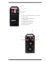
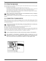
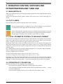
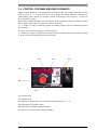
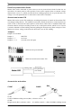
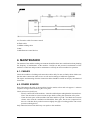
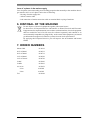
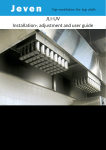
Operation instructions • english
Gebrauchsanweisung • deutsch
Gebruiksaanwijzing • nederlands
Manuel d’utilisation • français
MASTER
5001
1913270E
0541
CONTENTS
1. PREFACE ...................................................................................................................... 3
1.1. INTRODUCTION ......................................................................................................... 3
1.2. PRODUCT INTRODUCTION ...................................................................................... 3
1.3. OPERATION SAFETY................................................................................................. 3
2. INSTALLATION .............................................................................................................. 4
2.1. INSTALLATION ........................................................................................................... 4
2.2. SITING THE MACHINE ............................................................................................... 6
2.3. CONNECTION TO MAIN SUPPLY.............................................................................. 6
2.4. WELDING AND EARTH CABLES ............................................................................... 7
2.5. MOUNTING OF POWER UNIT TO TRANSPORT CARRIAGE .................................. 7
3. OPERATION CONTROL SWITCHES AND POTENTIOMETERS AND THEIR USE .... 8
3.1. MAIN SWITCH I/O....................................................................................................... 8
3.2. PILOT LAMPS ............................................................................................................. 8
3.3. LOCAL OR REMOTE CONTROL OF WELDING CURRENT ..................................... 8
3.4. OPERATION OF COOLING FAN ................................................................................ 8
3.5. CONTROL FOR MMA WELDING DYNAMICS ........................................................... 9
4. MAINTENANCE ............................................................................................................11
4.1. CABLES .....................................................................................................................11
4.2. POWER SOURCE......................................................................................................11
4.3. REGULAR MAINTENANCE ...................................................................................... 12
5. OPERATION DISTURBANCES ................................................................................... 12
6. DISPOSAL OF THE MACHINE ................................................................................... 13
7. ORDER NUMBERS ..................................................................................................... 13
8. TECHNICAL DATA ...................................................................................................... 14
9. TERMS OF GUARANTEE ........................................................................................... 15
2 – MASTER 5001/0541
© KEMPPI OY
1. PREFACE
1.1. INTRODUCTION
Congratulations on having purchased this product. Properly installed Kemppi products should
prove to be productive machines requiring maintenance at only regular intervals. This manual is
arranged to give you a good understanding of the equipment and its safe operation. It also contains
maintenance information and technical specifications. Read this manual from front to back before
installing, operating or maintaining the equipment for the first time. For further information on
Kemppi products please contact us or your nearest Kemppi distributor.
The specifications and designs presented in this manual are subject to change without prior
notice.
In this document, for danger to life or injury the following symbol is used:
Read the warning texts carefully and follow the instructions. Please also study the Operation safety
instructions and respect them when installing, operating and servicing the machine.
1.2. PRODUCT INTRODUCTION
Master 5001 is a 3-phase inverter power source for demanding professional use. Master 5001
is suitable for MMA welding and carbon arc gouging. It is also suitable as power source for arc
powered wire feeders. Master 5001 can also be used as power source for scratch-start/contact TIG.
Due to its high effect and excellent welding properties as well as due to its small size and light
weight it is very suitable for site welding as well as for repair and production welding.
In order to enable a good following of welding current the machine is equipped with well-visible
displays for welding current and welding voltage. Properties of Master 5001 can be improved with
remote control units and transport carts which are delivered as accessory.
1.3. OPERATION SAFETY
Never watch the arc without a face shield designed for arc welding!
The arc damages unprotected eyes! The arc burns unprotected skin!
Protect yourself and the surroundings against the arc and hot spray!
Remember general fire safety!
Pay attention to the fire safety regulations. Welding is always classified as a fire risk operation.
Welding where there is flammable or explosive material is strictly forbidden. If it is essential to
weld in such an area remove inflammable material from the immediate vicinity of the welding site.
Fire extinguishers must always be on site where welding is taking place.
Note! Sparks may cause ignition many hours after completion of welding.
Watch the mains voltage!
Take care of the cables - the connection cable must not be compressed, touch sharp edges or hot
work pieces. Faulty cables are always a fire risk and highly dangerous. Do not locate the welding
machine on wet surfaces. Do not take the welding machine inside the work piece (i.e. in containers,
cars etc.)
Ensure that neither you nor gas bottles or electricial equipment are in contact with live wires or
connections!
© KEMPPI OY
MASTER 5001/0541 – 3
Do not use faulty welding cables. Isolate yourself by using dry and not worn out protective clothes.
Do not weld on wet ground. Do not place the welding cables on the power source or other electricial
equipment.
Watch the welding fumes!
Ensure that there is sufficient ventilation. Follow special safety measures when you weld metals
which contain lead, cadmium, zinc, mercury and beryllium.
Note the danger caused by special welding jobs!
Watch the fire and explosion danger when welding container type work pieces.
2. INSTALLATION
2.1. INSTALLATION
P22
P23
R22
P21
R21
S21
P21 Current meter
P22 Voltage meter
P23 Display for adjustment value of MMA welding dynamics -9..0...9
R21 Ajustment of welding current
R22 Adjustment of MMA welding dynamics
S21 Selection for local/remote control/TIG/MIG
4 – MASTER 5001/0541
© KEMPPI OY
H12
H11
S11
F11 Fuse for remote control connection 1,0 A delayed
H11 Signal lamp I/O
H12 Warning lamp for thermal shield
S11 Main switch I/O
X11 Welding and earth connection
X 13 Welding and earth connection
X14 Remote control connection
01 Inlet of mains cable
X11
01
F11
© KEMPPI OY
X13
X14
MASTER 5001/0541 – 5
2.2. SITING THE MACHINE
Site the machine on a stationary, horizontal, dry base from which there does not come any dust
etc. into cooling air (front grate).
– Preferably site the machine somewhat higher above the floor level.
– See to that in front of the machine as well as at the rear of the machine there is at least 20
cm free distance to allow good circulation of the cooling air through the machine.
– Protect the machine against heavy rain and in hot circumstances against direct sunshine.
Ensure free circulation of the cooling air.
Degree of protection of machine IP23 allows at its maximum the water jet coming in
60° angle to hit machine´s outer covering.
See to that the machine is positioned away from the line of particle spray, created by grinding
tools etc.
2.3. CONNECTION TO MAIN SUPPLY
Master 5001 power source is delivered equipped with 5 m mains cable without plug. If local
electricity regulations of operating country are stating otherwise, the mains cable should be replaced
in conformity with them.
Connection of the mains cable and mounting of the plug should only be carried out by
a competent electrician.
Remove machine´s right side plate for the time you are mounting mains cable.
By change of the mains cable pay attention to the following:
The cable is entered into the machine through the inlet ring on the rear panel of the machine and
fastened with a cable clamp. The phase conductors of the cable are coupled to connectors L1, L2
and L3. The earth protection coloured green-yellow is coupled to connector.
If you are using 5-lead cable, you must connect neutral conductor with terminal N.
This equipment’s electromagnetic compatibility (EMC) is designed for use in an
industrial environment. Class A equipment is not intended for use in residential location
where the electrical power is provided by the public low-voltage supply system.
6 – MASTER 5001/0541
© KEMPPI OY
Sizes of the mains cables and fuseratings for the machine at 100 % dury cycle are specified in the
table below:
Master 5001
Rated voltage
3~ 400 V
Mains voltage range
400 V ± 10 %
Fuses, delayed
35 A
Connection cable mm²
4 x 6,0 S
In cables of S type there is a protective grounding conductor coloured green-yellow.
2.4. WELDING AND EARTH CABLES
Use only copper cables with cross-sectional area of at least 50 …95 mm².
In enclosed table are shown typical load capacities of rubber insulated copper cables, when ambient
temperature is 25ºC and lead temperature is 85 ºC.
Cable
Duty cycled ed
Voltage loss /10 m
100%
60%
30%
50mm²
285 A
370 A
520 A
0,35 V/ 100 A
70 mm²
355 A
460 A
650 A
0,25 V/ 100 A
95 mm²
430 A
560 A
790 A
0,18 V/ 100 A
Do not overload welding cables due to voltage losses and heating.
Fasten the earthing press of the return current cable carefully, preferably direct onto the piece to
be welded. The contact surface of the press should always be as large as possible.
Clean the fastening surface from paint and rust.
2.5. MOUNTING OF POWER UNIT TO TRANSPORT CARRIAGE
Read mounting instructions for Master 5001 power source delivered with carriage T12. Fasten
power source carefully of that the equipment should withstand lifting with lifting device.
© KEMPPI OY
MASTER 5001/0541 – 7
3. OPERATION CONTROL SWITCHES AND
POTENTIOMETERS AND THEIR USE
3.1. MAIN SWITCH I/O
When you use the switch into I-position, pilot lamp H11 on the front wall is lighted and the machine
is ready for use.
Always start and switch off the machine with the main switch, never use the mains plug as a
switch.
3.2. PILOT LAMPS
The pilot lamps of the machine report about the electric operation:
The green pilot lamp H11 for readiness for use is always lighted, when the machine
is connected to mains supply and the main switch is in I-position.
Yellow pilot lamp H12 of thermal protection is lighted when thermostat has released
due to overheating of machine. The cooling fan is cooling down the machine and when
the pilot lamp is switched off, the machine is again ready for welding.
3.3. LOCAL OR REMOTE CONTROL OF WELDING CURRENT
You can control welding current either from local control unit R21 of the machine or from remote
control unit C100C which is connected to remote control connector X14. When you are using the
remote control unit, the switch S21 must be in remote control position:
During the control, the set value of welding current can be seen on current meter display P21
and at the same time the no-load voltage of the machine can be seen on voltage display. During
welding the current meter P21 and the voltage meter P22 show welding current respectively
welding voltage.
Note! Voltage which can be seen during welding on display P22, is terminal voltage of machine,
which is voltage between terminals X11 and X13.
Accuracy of digital meter is as follows:
Accuracy of current true value in respect to real value is ±2,5%, ±2A.
Accuracy of voltage true value in respect to real value is ±2,5 %, ±0,2 V.
Depending on welding cable length and copper cross-section, real arc voltage and meter display
might differ many volts from each other. Error will increase when current is growing. See table in
paragraph “welding and earthing cables”. In current measurement the same error won´t appear.
3.4. OPERATION OF COOLING FAN
In Master 5001 there are two simultaneously operating fans.
– Fan is started for a moment, when main switch is placed into position I.
– Fan is started after welding start after machine has been heated and runs still for 1…10 min
time after welding stop.
– On no-load fan is started in intervals of ca. half an hour for a minute´s time.
8 – MASTER 5001/0541
© KEMPPI OY
3.5. CONTROL FOR MMA WELDING DYNAMICS
MMA welding dynamics is controlled with potentiometer R22. The potentiometer R22 has the
reference scale -9…0…9 can be seen also on the V display P22, which otherwise is showing noload/welding voltage. Setups for dynamics remain on the display still for approx. 3 s after you
have finished the control.
With control of MMA dynamics you can influence on arc in different situations. When you make
the arc harder, blow and at the same time spatter is increased.
-9…-1 Softer arc. Object: minimizing spatter in welding at upper end of recommended currents
for electrode.
0 Factory setup. Normal setting for all electrode types.
1…9 Harder arc. Object: eg cellulose covered electrodes (9) and thin stainless electrodes in welding
at lower end of recommended currents for electrode.
P22
P23
R22
P21
R21
S21
P21 Current meter
P22 Voltage meter
P23 Display for adjustment value of MMA welding dynamics -9…0…9.
R21 Adjustment of welding current
R22 Adjustment of MMA welding dynamics
S21 Selection for local/remote control/TIG/MIG
© KEMPPI OY
MASTER 5001/0541 – 9
Use of arc powered wire feeder
Master 5001 can be connected as power source to an arc powered wire feeder. In that case set
switch S21 of control panel to centre position. Power source operates then on constant voltage
characteristic curves (cv), which provides the best welding properties for arc powered units. Set
voltage is set with potentiometer or with remote control unit, if installed.
Scratch-start/contact TIG
Master 5001 can be used in TIG welding by switching the jumpers of control card to position TIG
(see jumper settings below). TIG welding is selected by setting switch S21 to centre position. Set
value of TIG is selected with control panel or with remote control unit, if installed. When TIG
electrode touches work piece welding current is on so called pilot current, which is 25 A. Current
is raised or reduced to actual welding current by pulling the electrode away from work piece. Note
that there is always voltage in the electrode when unit is set on TIG welding.
Jumpers
Jumpers on card A001:
Jumper 2
MIG/TIG
Jumpers 5 - 7
not in use
Jumpers 1, 3, 4
reserved (to be left open)
S 21
MMA and arc powered MIG
MMA and scratch-start/contact TIG
welding cable
arc powered
wire feeder
Accessoiries and cables
C100C
C100D
R62
R61
R61
C100C
Control of MMA welding current (R61), reference scale 1…10
C100D
Rough control (R61), reference scale 1…10, and fine control +/- (R62) for MMA welding current.
10 – MASTER 5001/0541
© KEMPPI OY
16c Extension cable for remote control
20 Earth cable
21 MMA welding cable
C100C
C100D Remote control devices
4. MAINTENANCE
The amount of use and the working environment should be taken into consideration when planning
the frequency of maintenance of the machine. Careful use and preventive maintenance of the
machine. Careful use and preventive maintenance will help to ensure trouble-free operation.
4.1. CABLES
Check the condition of welding and connection cables daily. Do not use faulty cables. Make sure
that the mains connection cables in use are safe and according to laid down regulations.
The repairs and mounting of mains connection cables should be carried out only by an authorised
electrician.
4.2. POWER SOURCE
Note! Disconnect the plug of the machine from the mains socket and wait approx. 2 minutes
(capacitor charge) before removing the cover plate.
Check at least every half year:
– Electric connections of the machine - clean the oxidized parts and tighten the loosened ones.
Note! You must know correct tension torques before starting the reparation of the joints.
– Clean the inner parts of the machine from dust and dirt eg with a soft brush and vacuum
cleaner. Also clean the ventilation net behind the front grate. Do not use compressed air,
there is a risk that dirt is packed even more tightly into gaps of cooling profiles. Do not use
pressure washing device.
Only authorised electrician shall carry out repairs to the machines.
© KEMPPI OY
MASTER 5001/0541 – 11
4.3. REGULAR MAINTENANCE
Kemppi service repair shops make regular maintenance according to agreement.
The major points in the maintenance procedure are listed as follows:
– cleaning of the machine
– checking and maintenance of the welding tools
– checking of connectors, switches and potentiometers
– checking of electric connections
– meter checking
– checking of mains cable and plug
– damaged parts of parts in bad connection are replaced by new ones
– maintenance testing. Operation and performance values of the machine are checked, and
adjusted when necessary by means of test equipment.
5. OPERATION DISTURBANCES
In case of problems contact the Kemppi works in Finland or your Kemppi dealer.
Check the maintenance objects before the machine is sent to the service repair shop.
Operation of the overload protection
Yellow pilot lamp H12 of thermal protection is lighted when thermostat has operated due to
overheating of machine.
The thermostat of machine will operate, if machine is continously loaded over rated values or
cooling air circulation is blocked.
Cooling fan cools down the machine and when the pilot lamp is not lighted the machine is
automatically ready for welding.
Control fuses
Fuse F11, 1,0 A delayed, on the rear wall of machine is as protection for connection of auxiliary
devices X14.
Use same type and rating of fuse which is marked beside the fuse adapter. Damage caused by a
wrong type of fuse is not covered by the guarantee.
Under- and overvoltages in the mains supply
Primary circuits of machine are protected against sudden, transient overvoltages. Machine is
designed to withstand 3 x 440 V voltage continously. See to it that voltage is kept within admissible
limits especially when mains supply is taken eg from combustion engine generator. If the mains
has undervoltage (under ca. 300 V), machine control stops automatically.
12 – MASTER 5001/0541
© KEMPPI OY
Loss of a phase in the mains supply
Loss of a phase causes noticeably poorer welding properties than normally or the machine doesn´t
get started at all. Loss of a phase can be due to following:
- blowing of mains supply fuse
- defective mains cable
- bad connection of mains connection cable on terminal block or plug of machine.
6. DISPOSAL OF THE MACHINE
Do not dispose of electrical equipment together with normal waste!
In observance of European Directive 2002/96/EC on Waste Electrical and Electronic
Equipment and its implementation in accordance with national law, electrical equipment
that has reached the end of its life must be collected separately and returned to an
environmentally compatible recycling facility. As the owner of the equipment, you should
get information on approved collection systems from our local representative.
By applying this European Directive you will improve the environment and human
health!
7. ORDER NUMBERS
Master 5001
6130512
20/5 m 50mm²
6184511
20/5 m 70mm²
6184711
21/5 m 50mm²
6184501
21/5 m 70 mm²
6184701
C100C
6185410
C100D
6185413
16c/10 m
6185451
/25 m
6185452
/50 m
6185453
T12
© KEMPPI OY
6185228
MASTER 5001/0541 – 13
8. TECHNICAL DATA
Master 5001
Mains voltage
Rated power
Connection cable
Fuse
Loading capacity
Control range for welding current
Max. welding voltage
Open circuit voltage
Open circuit power
Efficiency at nominal values
Power factor
Storage temperature range
Operation temperature range
Temperature class
Degree of protection
External dimensions
(without handles)
3~, 50/60 Hz
80 % ED
100 % ED
80 % ED
100 % ED
length
width
height
Weight
Voltage supply for auxiliary devices
fuse
400 V ± 10 %
500 A / 25,6 kVA
440 A / 20,2 kVA
4 x 6S - 5 m
35 A delayed
500 A / 40 V
440 A /37,6 V
10 A ... 500 A
50 V / 500 A
68 V
< 75 W
85 %
0,93
- 40 ... + 60 oC
- 20 ... + 40 oC
H (180 oC) / B (130 oC)
IP 23 C
530 mm
230 mm
520 mm
48 kg
50 V DC
1 A / delayed
The product meets conformity requirements for CE marking.
14 – MASTER 5001/0541
© KEMPPI OY
9. TERMS OF GUARANTEE
Kemppi Oy provides a guarantee for products manufactured and sold by them if defects in
manufacture and materials occur. Guarantee repairs must be carried out only by an Authorised
Kemppi Service Agent. Packing, freight and insurance costs to be paid by orderer. The guarantee is
effected on the date of purchase. Verbal promises which do not comply with the terms of guarantee
are not binding on guarantor.
Limitations on guarantee
The following conditions are not covered under the terms of guarantee: defects due to natural wear
and tear, non-compliance with operating and maintenance instructions, connection to incorrect or
faulty supply voltage (including voltage surges outside equipment spec.), incorrect gas pressure,
overloading, transport or storage damage, fire of damage due to natural causes i.e. lightning or
flooding.
This guarantee does not cover direct or indirect travelling costs, daily allowances or accommodation.
Note: Under the terms of guarantee, welding torches and their consumables, feeder drive rolls and
feeder guide tubes are not covered. Direct or indirect damage due to a defective product is not
covered under the guarantee. The guarantee is void if changes are made to the product without
approval of the manufacturer, or if repairs are carried out using non-approved spare parts.
The guarantee is also void if repairs are carried out by non-authorised agents.
Undertaking guarantee repairs
Guarantee defects must be informed to Kemppi or authorised Kemppi Service Agents within the
guarantee period. Before any guarantee work is undertaken, the customer must provide proof of
guarantee or proof of purchase, and serial number of the equipment in order to validate the guarantee.
The parts replaced under the terns of guarantee remain the property of Kemppi.
Following the guarantee repair, the guarantee of the machine or equipment, repaired or replaced,
will be continued to the end of the original guarantee period.
© KEMPPI OY
MASTER 5001/0541 – 15
KEMPPI OY
PL 13
FIN – 15801 LAHTI
FINLAND
Tel (03) 899 11
Telefax (03) 899 428
www.kemppi.com
KEMPPIKONEET OY
PL 13
FIN – 15801 LAHTI
FINLAND
Tel (03) 899 11
Telefax (03) 7348 398
e-mail: [email protected]
KEMPPI SVERIGE AB
Box 717
S – 194 27 UPPLANDS VÄSBY
SVERIGE
Tel (08) 59 078 300
Telefax (08) 59 082 394
e-mail: [email protected]
KEMPPI NORGE A/S
Postboks 2151, Postterminalen
N – 3103 TØNSBERG
NORGE
Tel 33 34 60 00
Telefax 33 34 60 10
e-mail: [email protected]
KEMPPI DANMARK A/S
Literbuen 11
DK – 2740 SKOVLUNDE
DANMARK
Tel 44 941 677
Telefax 44 941 536
e-mail:[email protected]
KEMPPI BENELUX B.V.
Postbus 5603
NL – 4801 EA BREDA
NEDERLAND
Tel (076) 5717 750
Telefax (076) 5716 345
e-mail: [email protected]
KEMPPI (UK) Ltd
Martti Kemppi Building
Fraser Road
Priory Business Park
BEDFORD, MK443WH
ENGLAND
Tel 0845 6444201
Fax 0845 6444202
e-mail: [email protected]
KEMPPI FRANCE S.A.
S.A. au capital de 5 000 000 F.
65 Avenue de la Couronne des Prés
78681 EPONE CEDEX
FRANCE
Tel (01) 30 90 04 40
Telefax (01) 30 90 04 45
e-mail: [email protected]
KEMPPI GmbH
Otto – Hahn – Straße 14
D – 35510 BUTZBACH
DEUTSCHLAND
Tel (06033) 88 020
Telefax (06033) 72 528
e-mail:[email protected]
KEMPPI SP. z o.o.
Ul. Piłsudskiego 2
05-091 ZA¸BKI
Poland
Tel +48 22 781 6162
Telefax +48 22 781 6505
e-mail: [email protected]
KEMPPI WELDING
MACHINES AUSTRALIA PTY LTD
P.O. Box 404 (2/58 Lancaster Street)
Ingleburn NSW 2565, Australia
Tel. +61-2-9605 9500
Telefax +61-2-9605 5999
e-mail: [email protected]
www.kemppi.com
Ver. 8