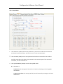
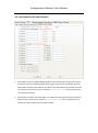
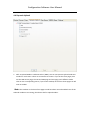
1
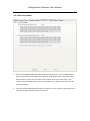
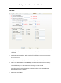
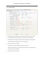
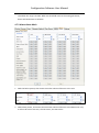
Configuration Software User Manual Gosafe G777/G797 Configuration Software User manual Configuration Software User Manual Table of Contents 1. General Note ......................................................................................................................... 4 1.1 The aim of this document................................................................................................ 4 1.2Copyright .......................................................................................................................... 4 1.3Reference materials ......................................................................................................... 4 2. Software Overview ................................................................................................................ 5 2.1Software usage ................................................................................................................. 5 2.2Software operation .......................................................................................................... 5 2.3Structure of the software ................................................................................................. 6 2.4installation of the USB driver for the software ................................................................ 6 3. G797 user interface overview ............................................................................................... 9 3.1 The tool is composed of these tabs: .......................................................................... 9 3.2 “Communication” explanation: ............................................................................ 10 3.3 “Function” ............................................................................................................... 10 3.4 “Device info”............................................................................................................ 11 4. Device Configuration ........................................................................................................... 12 4.1.1.Device-Software ...................................................................................................... 12 4.1.2.Device-Hardware ..................................................................................................... 13 4.2.1 Server-Main ................................................................................................................ 15 4.2.2 Server-SMS Sever ....................................................................................................... 17 4.2.3 Server-TCP/UDP Upload ............................................................................................. 18 4.3.1 User-Main ................................................................................................................... 20 4.3.2 User-SMS Forwarding & Shortcut Key ........................................................................ 22 4.3.3 User-Monitor & Communication ................................................................................ 23 4.4 Dynamic Upload ............................................................................................................ 24 4.5.1 Geo-Fence-Main ......................................................................................................... 25 4.5.2 Geo-Fence-Geo-Fence Setting .................................................................................... 26 4.6 OBDII .............................................................................................................................. 27 4.7.1 Alarm-Setting .............................................................................................................. 29 Configuration Software User Manual 4.7.2 Alarm-Alarm Mask ...................................................................................................... 30 4.8.1 Debug-Command........................................................................................................ 31 4.8.2 Debug-Debug .............................................................................................................. 32 Configuration Software User Manual 1. General Note 1.1 The aim of this document Gosafe provide this document to describe the functions and operation environment of configuration software, with the aim of providing a better understanding of using scope and approaches of the configuration software for the OEM manufacture, What’s more, this document also provides necessary maintaining and updating information for G797 configuration software. 1.2Copyright This document is a confidential document, Gosafe reserves all rights to this document and the information contained herein. Any individual or organization is strictly prohibited to reproduction, use or disclosure to the third party without permission. Otherwise, we hold the right to investigate the legal responsibility. Company address: B301-306, 69 Guangpu West Road, Science & Technology Park, Guangzhou, China. Tel: +86-20-66679696 E-mail: [email protected] Website: www.gosafesystem.com 1.3Reference materials G797 protocol and G797 user manual Configuration Software User Manual 2. Software Overview 2.1Software usage The Intended audiences of this document are the distributor and reseller of G797. Who use the G797 device, this document also provides a fast configuration tool. 2.2Software operation This software can be operated on both the PC and the compatible machine, it can be used with Microsoft windows (compatible windows 7), at first, you should decompress the software, and then click the Icons directly, then you can see the main menu of the software, you can configure the device as you need. The specific is as following: Configuration Software User Manual 2.3Structure of the software The software consists of three parts, which are configuration file —config.xml; APN list file —apnlist.txt and executable file —G797.exe. 2.4installation of the USB driver for the software Please connect our device to your computer, you will see the below picture: Then choose the options as the below picture show you Configuration Software User Manual Then click the ‘next’ button to go to the below picture, and we choose as the below picture show you. Please note that when you are choosing the ‘Browse’ button, you should choose the configuration file folder. You should choose the configuration file folder which has the “Anytracking USB.inf” document. Configuration Software User Manual Then press ‘next’ button, you will see the below picture. Finally the installation is finish and we get the below picture. Configuration Software User Manual Note: If you have not do the installation of the USB driver, the device will cannot be connected to your computer. 3. G797 user interface overview Once “G797S” is started, and connect to the computer correctly, the tool will start up as shown in Figure 1. —Figure 1— 3.1 The tool is composed of these tabs: 1. “Device”→”Software”+”Hardware” 2. “Server”→”Main”+”SMS Server”+”TCP/UDP Upload” 3. “User”→”Main”+”SMS Forwarding & Shutcut Key”+”Monitor & Communication” 4. “Dynamic Upload” Configuration Software User Manual 5. “Geo-Fence”→”Main”+”Geo-Fence setting” 6. “OBDII” 7. “Alarm”→”Setting”+”Alarm Mask” 8. “Debug”→”Command”+”Debug” Chose the function you need, to read and write the parameter. When the parameter is not correct, it will show “Command error!” 3.2 “Communication” explanation: 1. “Comm ports”→COM10 means the device is connect to Port No. 10 ( computer can automatic identification); 2. “Device Model”→G797 Product model:G797;Click the button, can choose the model; 3. “Password “→ default password is“0123456789”(the only one password which can automatic login the configuration status). 4. Button :“Connect” means the device is connect with the computer, when the password is not the default one, need to input the correct one and then press “Connect” button, then the device can login the configuration status; 5. Button: “Disconnect” means cancel the device connects with the computer; 3.3 “Function” 1. “Import”: means import configuration files; first of all, there must be one export configuration file which was exported before. Can use “Export” to export the configuration files. 2. “Export”: means export configuration files, it can correctly export the configuration parameter, first of all, must choose “√”. The purpose is to select the option which needs to be exported. Otherwise the files will be empty (invalid configuration files). Notes: when import the file, the content must be same as the export one. When setting for the bulk order, no need to select all, just choose the one you need, to avoid the error reminder. 3. “Reset”: means to set the parameters to default configuration; Configuration Software User Manual 4. “Restart”: means to restart the device; 5. select”√” here, means to choose all the function,; 6. “Read All”: means to read all the parameters which were chose. 7. “Write All”: means to write all the parameters which were chose. 3.4 “Device info” Device Name:G797 Device ID: 358696042235351 (Device ID) Hardware version:3.000 Hardware version Software version:3.052 Software version IMEI: 358696042235351 “International Mobile Equipment Identity” SIM MCC:460 , MNC:00 “To judge the device can read the SIM card or not” SIM ID: 89860090191149028638 The software contains eight setting pages; there are ”All”, ”Read” and ”Write” button. 1. “All”: press “All”, to choose all the optional that page have.。 a) For example: On “Device” page, ”Software” or ”Hardware” page, you click “All”; it will select all the optional under the “Device”. 2. ”Read”: Can only read the parameter which were chose“√”, click the “read” button, then you can read the parameter which device were set. 3. ”Write”: can only write the parameter which were chose“√”, click the “write” button, and then you can write the parameter into the device. Configuration Software User Manual 4. Device Configuration 4.1.1.Device-Software When read or write the parameter, the operation status information will show on the right of the page. Please see figure 2. —Figure 2— 1. Change PC Config Password (OPW): The device contain OEM password and the default password is 0123456789. This password can be changed by selecting this parameter. It is recommended that don’t change the OEM password. 2. Time Zone (TZN): The device can be set for the time zone. This time zone setting is only for the user. When user receives the SMS it will contain time and this time will be same as what time zone set in this parameter. 3. Daylight-Saving Time (DST): Set the daylight-saving time according to the actual situation. 4. Enable/Disable A-GPS (AGP): Enable disable A-GPS feature. Configuration Software User Manual 5. Enable/Disable Mileage (MGE): Enable disable mileage calculation feature. 6. Query/Set Mileage (MGR/MGS): The system can store the mileage of the vehicle which is 0 when the tracker is just installed and can add the future GPS mileage automatically in it. And you can also set the initial mileage on the tracker. Please note that the number we have to enter here is in meters. The default value is 0. 7. Power Save Mode (PSM): only when the upload time is larger than 15mins, device goes into power save. 4.1.2.Device-Hardware 1. Enable/Disable Movement Sensor (MOT): The system can enable disable the movement sensor. Note: The upload modes are depended on movement sensor. If the movement sensor is disabled the user will not receive “Move Alarm” and also the system will keep one upload mode. Configuration Software User Manual 2. Movement Sensor Setting (MTP): Vibrate duration is used when vehicle is in stop status and judge vehicle from stop to move. Stop duration is used to when vehicle is in moving status and judge vehicle from move to stop. The movement sensor parameters are to set the sensitivity of the movement sensor. Here we have three parameters Vibrate Threshold: Moving Last Time: This is time in seconds mean if the device moves for set time. Value range (1 ~ 255) Vibrate Duration: This number of movement in the set time. Value range (1~255) Stop Duration: This is time means if the vehicle stops for more than set time here will again send the move alarm to the user. If it stops less than set time here then it will not send the move alarm to user. Value range (1~255). 3. Serial Port Baud Rate (EPB): The device communication port baud rate can be set here. Click on the drop down menu to select the baud rate. Default is 9600 4. Serial Communication Protocol (EPS): when device connect to peripheral equipment, if choose “Protocol”, means device and equipment communicate each other by protocol. If choose “ Transparent”, means device only receive data and send to server. 5. Voice Volume (AGN): setting the volume of the Microphone and speaker. Configuration Software User Manual 4.2.1 Server-Main 1. APN List (APL): The APN list can be edit by pressing the Edit APN button. It will open a text file which contain all the APN list if set country APN is not available it can be added as follows: [ yyyy ] MCC=xxx; MNC=xx; APN=xxxxxxxx; USER NAME=xxxxxx; PW=xxxxxxx; MCC=xxx; MNC=xx; APN=xxxxxxxx; USER NAME=xxxxxx; PW=xxxxxxx; yyyy is country name MCC & MNC can get from the GSM service provider or can find from this link http://en.wikipedia.org/wiki/Mobile_Network_Code# Note that every GSM service provider has its own MCC and MNC. If the MCC and MNC are not correct the device will not set the APN. Configuration Software User Manual 2. APN (APN): APN: access point name; USER NAME: this is the user name of the APN if there is no user name can leave this blank PW: This is the password for the APN. If there is no password for the APN can leave this blank In the above example there are two GSM operator added. If there are more operators then just add more lines with their APN details. 3. GPRS Sever IP Port (SIP): Insert the IP and Port which the software located. 4. GPRS Sever Domain (SDM): Insert the Domain which the software located. 5. Upload Data Select (ADM): It can select what data device will upload to the server. There are six options 6. Heart Beat Interval (HBI): This is for setting the heart beat data uploading interval. Note that the number is Minute. 7. Change TCP Channel To UDP Channel (SOM): when enable the original TCP channel will use UDP to send all the original TCP relate data. All the setting of this new UDP channel will be same command as old TCP channel. 8. Upload From Extend Flash (EFS): Device can save the data (save over flow of 1K RAM or save all data) into flash and send to server. The data will not be lost even device power off. Configuration Software User Manual 4.2.2 Server-SMS Sever 1. Manager SMS Sever No. (SSN): You can get this NO. From your SIM card provider. This must be right, or you cannot get any messages from the device. 2. Manager SMS Sever Upload Mode 0 (SSM0): By this you decide disable or enable the SMS upload mode0. Parameter 1 G: GPS data: the message will tell you the location by showing you the longitude and latitude. S: Base station data: the message will tell you the location by showing you the base station data. Parameter 2 T: Text: the location datas’ format is text. Configuration Software User Manual Parameter 3 It is the interval of uploading the SMS. The value can be 30~900S, 15~59M, 1~240H. 3. Manager SMS Sever Upload Mode 1 (SSM1): By this, disable or enable the SMS upload mode0. 4.2.3 Server-TCP/UDP Upload 1. TCP Upload Mode 0 (TPM0): Enable and disable user upload mode0 Parameter 1 G: GPS data: the GPS data will be uploaded to the user phone No. S: Base station data: the Base station data will be uploaded to the user phone No. Parameter 2 Text: the location’s format will be text. Configuration Software User Manual Hyperlink: the location’s format will be hyperlink. Parameter 3 Data upload interval and voice monitor interval can be set. The value is 30~900S, 15~59M, 1~240H. 2. TCP Upload Mode 1 (TPM1): Same explain as the user upload0. This another user upload mode to choose 3. TCP Upload Buffer (TUP): You can set the quantity of records in every packet. When the records reach what you set, the device will upload the data automatically by the TCP channel. Note you have to enable the TCP Upload Buffer firstly. The device will keep uploading automatically once it reach on certain percent of 1kb, like 30% by the TCP channel. 4. UDP Upload Mode 0 (UPM0): Same explanation like the TCP upload mode. The only difference is that the upload channel changes to UDP channel 5. UDP Upload Mode 1 (UPM1): Same explain as the user upload0. This another user upload mode to choose 6. UDP Upload Buffer (UUP): Same explain as the TCP Upload Buffer (TUP). 7. Upload By Distance (DIS): The device will keep uploading automatically once it reach on certain distance by the TCP channel. 8. Upload By Angle Change (TRN): Enable and disable the angle change alert 9. Harsh Acceleration-GPS (SPD): Enable and disable the harsh acceleration-GPS. Select the times and the speed. When the parameter get to the setting speed and for the setting times. It will send alarm to software. Configuration Software User Manual 4.3.1 User-Main 1. User Phone No. (UNO): Set the user phone No. If you want to send some command to the device by the user phone, you have to set the same user phone No.. 2. User Password (UPW): Set the user password and confirm it. When the user needs to send the command to the device, the password is the essential part of the command. For details, see the command list. 3. User Upload Mode 0 (UUM0): to select the upload mode. Parameter 1 G: GPS data: the message will tell you the location by showing you the longitude and latitude. S: Base station data: the message will tell you the location by showing you the base station data. Configuration Software User Manual Parameter 2 T: Text: the location datas’ format is text. Parameter 3 It is the interval of uploading the SMS. The value can be 30~900S, 15~59M, 1~240H. 4. User Upload Mode 1 (UUM1): Same explain as the user upload0. This another user upload mode to choose 5. Hyperlink With GPS Data (URL0): This is the setting for the hyperlink which user receives if he set the W mode. The default setting is Google map link but this can be changed to specific map link like Bing, Yandex or open street map. And you have to give the setting parameters. And this one is for the GPS data 6. Hyperlink With Base Station Data (URL1): This is the setting for the hyperlink which user receives if he set the W mode. The default setting is nothing but this can be changed to specific format. And you have to give the setting parameters. And this one is for the LBS data. For details, see the protocol. Generally speaking, do not set this one 7. User Command Mask (UCM): This is used to allow which command the user can use. Configuration Software User Manual 4.3.2 User-SMS Forwarding & Shortcut Key 1. SMS Forwarding (SMT): Our device can transfer the SMS from certain No. to certain No. it is usually used to set transferring the SMS from the telecommunication company to the user, for example, the payment reminder SMS. 2. Shortcut Key (USC): You can set shortcut for the commands on this page, there are 10 shortcuts,each one corresponds with different command. The specific corresponding parameter command can also be saved in the cmd list of config.xml file in advance. Configuration Software User Manual 4.3.3 User-Monitor & Communication 1. Voice Monitor NO. List (VML) (VMM): Only the voice monitor No. can get the call from the device that can call automatically when it gets voice monitor command. And only when these numbers call the device, the device can automatically pick up the call to let you monitor. Once you set any No. of the list “”, then any phone No. can monitor the device 2. Hotline NO. List (HOT): The Hotline No. can achieve two way communications with the device. Once you set any No. of the list “”, then any phone No. can achieve two way communication with the device. Configuration Software User Manual 4.4 Dynamic Upload 1. Shift To Upload Mode 1 Condition Select: (DNU): You can set Dynamic upload mode 0 or mode1 for each status. There are six statuses to choose. If you set the front pages, that are the SMS Server page, the TCP and UDP page and user page, with different mode. Then on the corresponding status, if you choose mode0, all the front three pages set will work at mode0. Note: the condition is the three front pages mode have been set and enabled. One of the selected conditions is meeting, then device shift to upload mode1. Configuration Software User Manual 4.5.1 Geo-Fence-Main 1. Geo-Fence Enable/Disable (GOF): On the Geo-fence page, you can set enable/disable geo-fence and user mask of geo-fence. We have total 28 Geo-fences can store in the device memory. Then you can choose some of them or all to let them work. If you choose it like the below picture, then only number 8, 9,17,18,26 and 27 will work. The others won’t work 2. User Geo-Fence Enable/Disable (UFM): This means you can choose on which geo-fence the user can get the alarm if there is any alarm. Configuration Software User Manual 4.5.2 Geo-Fence-Geo-Fence Setting 1, Geo-Fence Setting: you can draw the Geo-fence here. Parameter 1, Draw type: select the draw type, there are round, rectangle and polygon type. Parameter 2, No.: name of the geo-fence. Parameter 3, Type: there are Geo-fence in, Geo-fence out and In Or Out. Select one of the alarm statuses. Notes: the Geo-fence here draws which cannot be shown on the website. But can be use also. Configuration Software User Manual 4.6 OBDII 1. Fuel Coefficient (OBP16): To calculate the fuel consumption, first should choose the fuel coefficient. 2. Initial Fuel Consumption (FCI): Only when the fuel coefficient is correct and not empty, this can be correct. 3. Query Fuel Consumption (FUC): Check fuel consumption, just for query, cannot be set. 4. Vehicle Low Battery Alarm Threshold (OBA0): Setting the threshold of the low battery. Threshold: the range is 0~25.5 V; Duration: the range is 0~255 second. When the threshold reach to the setting parameter and last for the setting duration, device will send alarm to software. 5. Engine Over Heat (OBA1): Configuration Software User Manual Threshold: the range is -40~215℃, Duration range is 0~255 second. When the threshold reach to the setting parameter and last for the setting duration, device will send alarm to software. 6. Engine Over Revving (OBA2): Threshold: the range is 0~25.5KRPM, Duration range is 0~255 second. When the threshold reach to the setting parameter and last for the setting duration, device will send alarm to software. 7. OBD Data Upload Select (OBP): This one is for setting OBDII data uploading. It will decide which OBDII data can be uploaded. When you check your vehicle’s protocol, and you know which one is open by the vehicle manufacturer, you can just choose one of the 15 OBP data which have not been used for any OBDII data uploading, and then input the OBDII code you decide to upload. Click it like the below picture, then press the “write” button. In the future, you will get this OBDII data. Configuration Software User Manual 4.7.1 Alarm-Setting 1. Enable/Disable Over-Speed Alarm (SPO): Enable disable Over-speed alarm feature. 2. Over-Speed Parameter (SOP): setting the parameter of the over-speed alarm. 3. Enable/Disable Anti-Jamming Alarm (JAM): Enable and disable anti-jamming mask. Enable and disable immobilizing the car when anti-jamming. 4. Harsh Acceleration G-force (HGV): Threshold: the range is 0~8.0G, Duration range is 0.2~2 second. When the threshold reach to the setting parameter and last for the setting duration, device will send alarm to software. 5. Accident Detection G-force (AGV): Configuration Software User Manual Threshold: the range is 0~8.0G. When the threshold reach to the setting parameter, device will send alarm to software. 4.7.2 Alarm-Alarm Mask 1. With the below picture, that means Auto Clear alarm will be sent to the user. 2. With below picture, that means the Auto Clear alarm will be sent to the SMS server only. It will not be sent to the user, the TCP server, the UDP server. Configuration Software User Manual 4.8.1 Debug-Command Input the command to set the configuration parameter directly here. Configuration Software User Manual 4.8.2 Debug-Debug Read the GPS and GSM original data here.