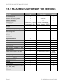
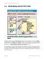
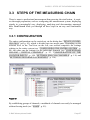
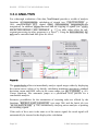
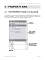
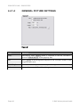
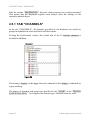
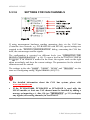
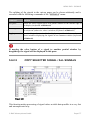
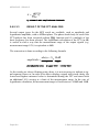
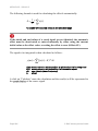
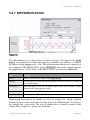
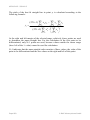
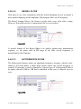
1
NextView®4
Software for Acquisition and
Processing of Measuring Data
User Manual
Version 4.6
TABLE OF CONTENTS
Table of Contents
1 OVERVIEW
9
1.1
1.2
1.3
1.4
1.5
INTRODUCTION
SYSTEM REQUIREMENTS
BMC MESSSYSTEME GMBH
COPYRIGHTS
NEXTVIEW®4 VERSIONS
1.5.1 DIFFERENCES OF THE VERSIONS
1.5.2 FEATURES/FUNCTIONS OF THE VERSIONS
1.6 COMPATIBILITY WITH NVNT 3.X
1.7 COMPATIBLE HARDWARE
2 FIRST START
9
10
11
12
13
13
14
16
17
19
2.1 STARTING THE SOFTWARE
2.2 LICENSING
2.3 DEVICE SETUP (PRO, LITE, TRIAL)
3 BASICS
19
20
23
25
3.1 NEXTVIEW®4 USER INTERFACE
3.2 PROGRAM ARCHITECTURE
3.3 STEPS OF THE MEASURING CHAIN
3.3.1 CONFIGURATION
3.3.2 ACQUISITION
3.3.3 VISUALIZATION
3.3.3.1
3.3.3.2
3.3.3.3
LIVE DATA IN CHART RECORDER VIEW
SIGNAL SETTINGS
OTHER DISPLAYS
3.3.4 ANALYSIS
3.3.5 DOCUMENTATION
3.4 MULTI-SCAN
© BMC Messsysteme GmbH
25
26
27
27
28
29
30
30
31
32
33
34
Page iii
TABLE OF CONTENTS
3.5 KEY ASSIGNMENT AND SHORTCUTS
35
4 PROPERTY BAR
39
4.1 THE PROPERTY BAR AT A GLANCE
4.2 OPERATION
4.3 COMMON TASKS
4.3.1 TAB "PROJECT"
4.3.2 TAB "DEVICES"
4.3.3 TAB "START/STOP"
4.4 PROPERTIES
4.4.1 TAB "GENERAL"
4.4.1.1
4.4.1.2
4.4.1.3
4.4.1.4
4.4.1.5
4.4.1.6
39
40
41
41
42
42
43
44
GENERAL SHEET SETTINGS
LIVE DISPLAY, GRAPH DISPLAY
STATIC TEXT, DIGITAL MULTIMETER
GENERAL PICTURE SETTINGS
LEVEL INDICATOR, SLIDER, BUTTON
MESSAGE DISPLAYS
4.4.2 TAB "STATE"
4.4.3 TAB "COLOR"
4.4.3.1
4.4.3.2
4.4.3.3
4.4.3.4
44
44
45
46
47
48
49
50
ADJUST DEFAULT COLORS
LIVE DISPLAY, GRAPH DISPLAY
DIGITAL MULTIMETER, LEVEL INDICATOR
STATIC TEXT, BUTTON
50
51
52
54
4.4.4 TAB "FONT"
4.4.5 TAB "SIGNAL"
4.4.6 TAB "X-AXIS"
4.4.7 TAB "Y-AXIS"
4.4.8 TAB "CURSOR"
4.4.9 TAB "SCRIPT"
4.5 RESOURCES
4.5.1 TAB "CHANNELS"
4.5.2 TAB "SIGNALS"
55
56
58
59
60
63
63
64
66
4.5.2.1
4.5.2.2
4.5.2.3
4.5.2.4
67
69
70
71
Page iv
OPEN / SAVE SIGNAL FILES
IMPORT
INSERT A SIGNAL TO A DISPLAY
FILE TRAIN
© BMC Messsysteme GmbH
TABLE OF CONTENTS
4.5.2.4.1
4.5.2.4.2
CREATE FILE TRAIN
REMOVE FILES FROM TRAIN
4.5.3 TAB "PROJECT"
74
5 MENU BAR
75
5.1 FILE
5.1.1 COMMANDS OF THE MENU "FILE"
5.1.2 PROJECT
5.1.3 OPEN SIGNAL FILE
5.1.4 PRINT
5.1.4.1
5.1.4.2
5.1.4.3
5.1.4.4
71
73
PRINT SETTINGS
PRINT PREVIEW
PRINT INTO CLIPBOARD
PAGE SETUP
5.1.5 DIRECT START OF PROJECTS
5.1.6 EXIT
5.2 EDIT
5.3 DEVICE
5.3.1 COMMANDS OF THE MENU "DEVICE"
5.3.2 START / STOP SCANNING
5.3.3 DEVICE CONFIGURATION
75
75
76
77
77
78
79
80
81
82
82
83
84
84
85
85
5.3.3.1
5.3.3.2
5.3.3.3
OPERATING THE DEVICE CONFIGURATION
ILLUSTRATING THE MEASUREMENT SETUP
CONFIGURING THE ENTIRE SYSTEM
86
87
88
5.3.3.4
CONFIGURING ANALOG / DIGITAL CHANNELS
94
5.3.3.5
5.3.3.6
5.3.3.3.1
5.3.3.3.2
5.3.3.3.3
5.3.3.3.4
SCAN
FILE
LIVE DATA
CLOCK
5.3.3.4.1
5.3.3.4.2
5.3.3.4.3
5.3.3.4.4
5.3.3.4.5
5.3.3.4.6
5.3.3.4.7
5.3.3.4.8
NAME
INPUT
DEFAULTS
USING
SCAN
TRIGGER
OUTPUT
LINES
5.3.3.5.1
5.3.3.5.2
RANGE
COUNTER
88
90
91
92
95
97
99
100
101
104
105
107
CONFIGURATION OF THE COUNTER INPUTS
108
SETTINGS FOR CAN CHANNELS
110
© BMC Messsysteme GmbH
108
108
Page v
TABLE OF CONTENTS
5.3.3.7
5.3.3.6.1
5.3.3.6.2
5.3.3.6.3
5.3.3.6.4
5.3.3.6.5
MESSAGES
BUS
MESSAGE
SIGNALS
CAN
5.3.3.7.1
5.3.3.7.2
FORMULA CHANNELS
FORMULA
SETTINGS FOR FORMULA CHANNELS
5.3.4 SCAN CONFIGURATION
5.3.4.1
5.3.4.2
NOTES TO THE "SCAN CONFIGURATION"
OPERATION
STATIC TEXT: ACTIVE AND INACTIVE STATE
STATIC TEXT: ASSIGN CHANNEL
133
134
137
137
138
LEVEL INDICATOR: ACTIVE / INACTIVE
LEVEL INDICATOR: ASSIGN CHANNEL
5.5.7 LIVE DISPLAY
140
141
142
5.5.7.1
5.5.7.2
5.5.7.3
5.5.7.4
TRANSMISSION OF LIVE DATA
ENVELOPE CURVE
NAVIGATING THE DISPLAY
LIVE DISPLAY: BUTTONS
144
145
146
147
5.5.7.5
5.5.7.6
LIVE DISPLAY: ASSIGN CHANNEL
SETTINGS OF THE LIVE DISPLAY
150
151
5.5.7.4.1
5.5.7.4.2
5.5.8 BUTTON
Page vi
125
125
126
128
129
129
130
132
135
DVM: ACTIVE AND INACTIVE STATE
DVM: ASSIGN CHANNEL
5.5.6 LEVEL INDICATOR
5.5.6.1
5.5.6.2
120
122
124
124
5.5.5 DIGITAL MULTIMETER
5.5.5.1
5.5.5.2
116
118
124
LOAD / SAVE CONFIGURATION
PRINT CONFIGURATION
5.3.6 RESTORE DEFAULTS
5.3.7 RECENT CONFIGURATION
5.4 SHEET
5.5 DISPLAY
5.5.1 COMMANDS OF THE MENU "DISPLAY"
5.5.2 POSITION AND SIZE
5.5.3 PICTURE
5.5.4 STATIC TEXT
5.5.4.1
5.5.4.2
116
120
5.3.5 CONFIGURATION FILE (*.NVC)
5.3.5.1
5.3.5.2
111
112
113
114
115
ZOOMING IN THE DISPLAY
100% REPRESENTATION
148
149
153
© BMC Messsysteme GmbH
TABLE OF CONTENTS
5.5.8.1
5.5.8.2
BUTTON: ASSIGN DIGITAL OUTPUT
BUTTON: OPERATION
5.5.9 SLIDER
5.5.9.1
5.5.9.2
154
155
156
SLIDER: ASSIGN ANALOG OUTPUT
SLIDER: OPERATION
5.5.10 GRAPH DISPLAY
157
158
159
5.5.10.1 REPRESENTATION OF STORED VALUES
5.5.10.2 GRAPH DISPLAY: BUTTONS
162
164
5.5.10.3 GRAPH DISPLAY: ASSIGN SIGNAL
5.5.10.4 SETTINGS OF THE GRAPH DISPLAY
167
169
5.5.10.2.1 CURSORS
5.5.10.2.2 X/Y-REPRESENTATION
5.5.10.2.3 FFT MARKER
5.5.11 MESSAGE DISPLAY
5.6 SIGNALS
5.6.1 COMMANDS OF THE MENU "SIGNAL"
5.6.2 SIGNAL COMMANDS
5.6.2.1
5.6.2.2
5.6.2.3
5.6.2.4
5.6.2.5
ADD SIGNAL
HIDE SIGNAL
DELETE SIGNAL
PANE VIEW
COPY SELECTED SIGNAL / ALL SIGNALS
5.6.3 EXPORT
5.6.3.1
5.6.3.2
TAB "OPTIONS"
5.6.4 CALCULATION
5.6.4.1
5.6.4.2
ENTER FORMULA
CHOOSE A SIGNAL
180
182
183
185
187
188
SETTINGS FOR THE FFT ANALYSIS
MULTIPLE FFT ANALYSIS
NOTES FOR FFT ANALYSIS
5.6.5.3.1
5.6.5.3.2
5.6.5.3.3
TYPES OF SOURCE SIGNALS
WINDOW FUNCTIONS
RESULT OF THE FFT ANALYSIS
5.6.6 INTEGRATION
5.6.7 DIFFERENTIATION
5.6.8 FILTER
5.6.8.1
174
174
175
176
177
184
5.6.5 FFT
5.6.5.1
5.6.5.2
5.6.5.3
170
172
173
174
179
EXPORT WITHIN NEXTVIEW®4
ASCII EXPORT
5.6.3.2.1
165
166
167
SETTINGS FOR DIGITAL FILTERS
© BMC Messsysteme GmbH
189
190
192
192
193
194
195
197
199
199
Page vii
TABLE OF CONTENTS
5.6.8.2
5.6.8.1.1
5.6.8.1.2
5.6.8.1.3
FILTER TYPE
FILTER ORDER
FILTER METHOD
5.6.8.2.1
5.6.8.2.2
5.6.8.2.3
5.6.8.2.4
CRITICAL DAMPING
BESSEL FILTER
BUTTERWORTH FILTER
TSCHEBYSCHEFF FILTER
PROS AND CONS OF THE VARIOUS FILTERS
5.6.9 DATA REDUCTION
5.6.10 REPEAT LAST ANALYSIS
5.6.11 SETUP BATCH JOB
SETTINGS FOR ANALYSIS
SELECT SIGNAL
BATCH JOB OPTIONS
PRINT BATCH JOB
5.6.11.2 BATCH JOB: TYPICAL APPLICATIONS
5.6.12 RUN BATCH JOB
5.7 OPTIONS
5.7.1 COMMANDS OF THE MENU "OPTIONS"
5.7.2 PREFERENCES
5.7.2.1
5.7.2.2
GENERAL OPTIONS
PRINTING OPTIONS
5.7.3 PROJECT OPTIONS
5.7.4 LOCK PROJECT
5.7.5 LICENSE
5.7.6 UPDATE NEXTVIEW®
5.7.7 SEND BUG REPORT
5.7.8 VIEW...
5.8 HELP
5.8.1 HELP TOPICS
5.8.2 NEXTVIEW®4 VERSIONS
5.8.3 KEYBOARD MAP AND SHORTCUTS
5.8.4 NEXTVIEW®4 SCRIPT
5.8.5 ABOUT NEXTVIEW®4
6 INDEX
Page viii
202
202
203
203
204
205
206
208
5.6.11.1 SETTINGS FOR THE BATCH JOB
5.6.11.1.1
5.6.11.1.2
5.6.11.1.3
5.6.11.1.4
200
201
201
208
210
210
211
212
213
214
215
215
216
216
217
218
218
219
219
220
220
221
221
221
221
222
222
223
© BMC Messsysteme GmbH
OVERVIEW - INTRODUCTION
1
OVERVIEW
1.1 INTRODUCTION
Figure 1
NextView®4 is a universal program for the acquisition and analysis of measured
data providing for the configuration of data acquisition systems and PC measuring
cards, the display of live data, as well as storage and analysis of measured data.
The MS-DOS-version of NextView® had already been a great success for many
years and had constantly been improved.
We set our focus on ease of operation, practical relevance and professionalism.
NextView®4 is a powerful tool which allows you to execute a great variety of
measurements, completely, reliably and efficiently without a bulk of programming
work beforehand being necessary.
© BMC Messsysteme GmbH
Page 9
OVERVIEW - SYSTEM REQUIREMENTS
In addition, the operation of NextView®4 follows the Windows® conventions,
reducing the lead-in period drastically.
NextView®4 guarantees high-speed processing of almost any number of data sets.
NextView®4 provides various types of DAQ hardware (LAN, USB, PCIe, PCI) to
combine with (see "COMPATIBLE HARDWARE", p. 17).
With the add-on module NextView®4 Script (not free of charge), you can
control processes and realize individual applications.
1.2 SYSTEM REQUIREMENTS
minimum:
recommended:
®
PC with Windows XP/7/8
PC with Windows® XP/7/8
Pentium processor, 400MHz
Pentium processor, 1GHz
256MB RAM
512MB RAM
hard disc >50MB
hard disc >200MB
graphics card 1024x768,
256 colors
graphics card 1600x1200,
True Color
Page 10
© BMC Messsysteme GmbH
OVERVIEW - BMC MESSSYSTEME GMBH
1.3 BMC MESSSYSTEME GMBH
BMC Messsysteme GmbH stands for innovative measuring technology made in
Germany. We provide all components required for the measuring chain, from
sensor to software.
Our hardware and software components are perfectly tuned with each other to
produce an extremely user-friendly integrated system. We put great emphasis on
observing current industrial standards, which facilitate the interaction of many
components.
Products by BMC Messsysteme are applied in industrial large-scale enterprises, in
research and development and in private applications. We produce in compliance
with ISO-9000-standards because standards and reliability are of paramount
importance to us - for your profit and success.
Please visit us on the web (http://www.bmcm.de) for detailed information and
latest news.
© BMC Messsysteme GmbH
Page 11
OVERVIEW - COPYRIGHTS
1.4 COPYRIGHTS
The software NextView®4 has been developed and tested with utmost care. BMC
Messsysteme GmbH does not provide any guarantee in respect of this manual, the
hard- and software described in it, its quality, its performance or fitness for a
particular purpose. BMC Messsysteme GmbH is not liable in any case for direct or
indirect damages or consequential damages which may arise from improper
operation or any faults whatsoever of the system. The system is subject to changes
and alterations which serve the purpose of technical improvement.
The software NextView®4, the manual provided with it and all names, brands,
pictures, other expressions and symbols are protected by law as well as by national
and international contracts. The rights established therefrom, in particular those for
translation, reprint, extraction of depictions, broadcasting, photomechanical or
similar way of reproduction - no matter if used in part or in whole - are reserved.
Reproduction of the programs and the manual as well as passing them on to others
is not permitted. Illegal use or other legal impairment will be prosecuted by
criminal and civil law and may lead to severe sanctions.
Copyright © 2014
BMC Messsysteme GmbH
Updated: 09/20/2014
Hauptstrasse 21
82216 Maisach
GERMANY
Phone: +49 8141/404180-0
Fax: +49 8141/404180-9
E-mail: [email protected]
Page 12
© BMC Messsysteme GmbH
OVERVIEW - NEXTVIEW®4 VERSIONS
1.5 NEXTVIEW®4 VERSIONS
1.5.1 DIFFERENCES OF THE VERSIONS
You can choose between varying standalone versions of NextView®4 depending
on your specific requirements:
NextView®4 Trial - fully functional 30-day trial version
NextView®4 Lite - the "slim" version of NextView®4
NextView®4 Professional - professional data acquisition for all application fields
NextView®4 Analysis - for a well-founded analysis of recorded data by means of
the powerful NextView®4 analysis functions
•
NextView®4 can be used as a free trial for 30 days. The trial features all
functions of a Professional version.
•
Changing to another version does not require reinstalling (see
"LICENSE", p. 219). All projects, measuring files and settings created
with the trial version can still be used.
•
If a chargeable version has not been purchased within the first 30 days,
the functional range of NextView®4 will be reduced considerably.
© BMC Messsysteme GmbH
Page 13
OVERVIEW - NEXTVIEW®4 VERSIONS
1.5.2 FEATURES/FUNCTIONS OF THE VERSIONS
function
Lite
Pro, Trial
Analysis
license required
+
+
+
number of DAQ systems
1
unlimited
-
formula channels
-
16
-
current value, mean
value (rate 1:20)
current value, mean
value, min, max, RMS
-
trigger
-
+
-
multi-scan
-
+
-
automatic numbering of
measuring files
+
+
-
picture
-
+
+
static text
+
+
-
digital multimeter
+
+
-
level indicator
-
+
-
active alarm function
+
+
-
live display
+
+
-
stop, reverse, zoom in live data
-
+
-
graph display
+
+
+
signal representation in panes
-
live and graph displays
graph
displays
edit signal parameters
-
+
+
hide, delete signals
+
+
+
x/y-representation
-
+
+
cursors
+
+
+
cursor jumps
-
+
+
calculation of signal key values
(e.g. min, max)
-
+
+
file train
-
+
+
storage types
Page 14
© BMC Messsysteme GmbH
OVERVIEW - NEXTVIEW®4 VERSIONS
function
Lite
Pro
Analysis
+
+
+
-
+
+
-
+
+
calculation of signal values
-
+
+
integration
-
+
+
differentiation
-
+
+
FFT
-
+
+
digital filters
-
+
+
repeat last analysis
-
+
+
setup batch job
-
+
+
message display
+
+
+
button
-
+
+
slider
-
+
-
export
1
export signal values
import
2
NextView®4 Script option 3
+
+
+
save project
+
+
+
lock project
+
+
+
print sheet
+
+
+
print active graph display /
message display
+
+
+
print preview
+
+
+
1
2
3
®
export: ASCII, Diadem, TurboLab, NextView®4, NextView /NT 3.4
import: ASCII, Diadem, ModuLab, NextView®, TurboLab, data base
subjext to a charge
© BMC Messsysteme GmbH
Page 15
OVERVIEW - COMPATIBILITY WITH NVNT 3.X
1.6 COMPATIBILITY WITH NVNT 3.X
When developing NextView®4, we put an emphasis on highest software compatibility to the previous version NextView®/NT 3.x.
The following table shows the usability of project, configuration and measurement
files of the two versions.
file
project file (*.nvp)
configuration file (*.nvc)
last stored in version
open and use in version
3.x
3.x, 4.x
4.x
4.x
3.x
3.x, 4.x
4.x
4.x
measurement and analysis file
3.x
3.x, 4.x
(*.lfx)
4.x
4.x, export in 3.4
Be careful when saving a project or configuration file in NextView®4 created
with version 3.x, because afterwards those cannot be opened by
NextView®/NT 3.x anymore!
Page 16
© BMC Messsysteme GmbH
OVERVIEW - COMPATIBLE HARDWARE
1.7 COMPATIBLE HARDWARE
Figure 2
NextView®4 supports the complete product range of the bmcm measuring
hardware currently available.
The sampled data are directly recorded, displayed, parameterized and stored to the
hard disk by means of a DAQ system externally connected to the PC (USB, LAN)
or a PC data acquisition card installed in the PC (PCI, PCIe).
The number of connected hardware in NextView®4 Professional is not limited by
the software (NextView®4 Lite: 1). Even DAQ systems of different type can be
installed, and several sensors of a diverse range of sensor technology may be
connected to the devices.
The follwing table shows the supported device types. The category "Sampling rate"
specifies the maximum scan frequency to be used, if exactly one channel is stored.
The specified performance data only apply together with NextView®4!
For devices sampling asynchronously, the PC time is consistent with the scan time.
The other measuring systems provide an integrated microcontroller for highprecision sampling in µ-seconds using its own time base. Because of slightest
inaccuracies of the quartz, the times used by the DAQ system and by the PC can
diverge.
© BMC Messsysteme GmbH
Page 17
OVERVIEW - COMPATIBLE HARDWARE
compatible
hardware
LAN-AD16fx
analog
digital
resolu- max. sampl. total sampl.
IN OUT IN
OUT C
tion rate / 1 channel
rate
3
5
16
2
2x16
3
16
250kHz
250kHz
LAN-AD16f
16
2
16
16
15
16
250kHz
250kHz
iM-AD25(a)
16
-
-
4
-
16
25kHz
25kHz
iM3250(T)
32
-
16
25kHz
25kHz
USB-AD16f
16
2
4
4
1
16
250kHz
250kHz
USB-AD14f
16
1
8
8
1
14
20kHz
20kHz
4
5
12
20kHz
20kHz
USB-AD12f
1
USB-AD
16
1
-
4
1
16
1
4
4
-
12
10Hz
160Hz
USB-OI161
-
-
16
16
2
-
10Hz
2404Hz
USB-PIO1
-
-
-
-
10Hz
2404Hz
3x83
meM-AD1
16
-
-
-
-
10
10Hz
160Hz
meM-ADDA1
16
1
4
4
-
12
10Hz
160Hz
meM-ADf
16
1
4
4
-
12
10kHz
10kHz
meM-ADfo
8
-
12
10kHz
10kHz
-
3
-
-
-
-
-
10Hz
2404Hz
-
12/16
333kHz
333kHz
16
1
8
meM-INC
1
-
-
-
meM-PIO1
-
-
16-32
2-16
16
16
16
16
PCI-BASE3002
2
PCI-BASE1000
16-32
2-16
PCI-BASEII2
16-32
2-16
PCI-PIO
PCIe-BASE
2
16-32
2-16
3x83
-
12/16
500kHz
1MHz
2x163
35
12/16
500kHz
1MHz
3
5
-
1MHz
1MHz
5
12/16
500kHz
1MHz
2x16
2x16
3
3
3
1
asynchronous sampling
depending on the used module plugged on the card
switchable between input and output in groups of 8,
USB-PIO, meM-PIO: C-port switchable in groups of 4
4
total sampling rate of all lines
5
connect counter/incremental encoder at digital input lines
2
3
Page 18
© BMC Messsysteme GmbH
FIRST START - STARTING THE SOFTWARE
2
FIRST START
2.1 STARTING THE SOFTWARE
Figure 3
NextView®4 is started via the Windows® Start Menu on the destop or by selecting
the program file nextview.exe in the installed directory.
Windows®8 provides additional tiles for NextView®4 and Hardware Setup (see
"DEVICE SETUP (PRO, LITE, TRIAL)" on page 23) auf dem Startbildschirm.
© BMC Messsysteme GmbH
Page 19
FIRST START - LICENSING
If default settings have been used during installation, the software can be reached
as follows:
NextView®4
Windows® Start Menu:
Windows® Explorer:
"All Programs" program group "NextView 4.x"
software "NextView 4"
C:\Program Files\NextView 4.x\nextview.exe
•
When starting the software, the DAQ hardware to be used must have
been connected and, if necessary, turned on!
•
Upon the initial start of NextView®4, licensing has to be done first and
then the device setup (Pro, Lite, Trial).
2.2 LICENSING
Upon the initial start, NextView®4 asks for various user data.
Figure 4
Page 20
© BMC Messsysteme GmbH
FIRST START - LICENSING
Holders of NextView®4 Lite, Pro, Analysis:
Owners of a Lite, Pro, or Analysis version enter the 10-digit serial number
received upon purchase of NextView®4.
NextView®4 Trial version:
If you want to test the 30-day trial version, checkmark the option "30 days free
trial version". In this case, entering a serial number is not necessary.
Update NextView®4.x
NextView®4.6:
To install a free update of a previous 4.x version, enter the old 4.x license
number (20-digit) in the field of the serial number. This also applies to users of
the Live! version. The old license number is provided in the "License" dialog
(menu "Options") of the previous 4.x version of NextView®4.
Click the button "Request License". After accepting the licensing agreement, you
can choose if you want to request the license number via e-mail or via our website.
Figure 5
Request license number via e-mail:
If selecting this option, your e-mail program will automatically be opened. The
e-mail shown contains important data required for licensing and must not be
© BMC Messsysteme GmbH
Page 21
FIRST START - LICENSING
changed. Send the e-mail ([email protected]) for the license number to be
sent to your e-mail address.
Request license number via internet:
The button "Open browser now" automatically starts the default browser and
the webpage "NextView® Licensing" (also accessible via: www.nextview.de)
will be opened displaying your licensing data. Now enter the e-mail address to
which you want the license number to be sent.
Figure 6
To complete the licensing process, enter the license number (25-digit) received by
e-mail in the NextView®4 dialog "Licensing" and press "OK".
Page 22
© BMC Messsysteme GmbH
FIRST START - DEVICE SETUP (PRO, LITE, TRIAL)
•
The license number decides about the version (Trial, Lite, Pro, Analysis)
to be installed. It is only valid on the PC requesting the license number.
•
The trial is valid for 30 days after requesting the license number. If a
license is not purchased within this period, the functional range of
NextView®4 will considerably be cut back.
•
Now proceed with the device setup (Pro, Lite, Trial).
2.3 DEVICE SETUP (PRO, LITE, TRIAL)
Figure 7
© BMC Messsysteme GmbH
Page 23
FIRST START - DEVICE SETUP (PRO, LITE, TRIAL)
After the licensing process when first starting the program, the measurement
hardware is selected and configured. The dialog "Device Setup" (Lite, Pro, Trial)
shows all installed and connected data acquisition systems.
Measurement hardware to be used with NextView®4 is selected by placing a
checkmark next to the device in the bottom field. In addition, 16 formula channels
can be installed.
With the sound card, audio signals can be displayed, recorded and analyzed in
NextView®4 allowing the use of the 30-day trial license without bmcm measuring
hardware.
It is strongly recommended to verify the device-specific properties of some DAQ
systems before installation by selecting the device in the top field and pressing the
button "Properties…" which is active now.
DAQ system
Setting
LAN data
acquisition system
(iM series)
Selection of virtual channels 17-19:
• temperature sensor (measures internal device temperature)
• hot-wired ground channel as 0V reference
• clock signal for external synchronization
PCI(e) ) data
acquisition card
(PCI/PCIe series)
To check the module configuration, select the module and press
"Properties".
• input modules (MAD series): operating mode (singleended/differential)
• output modules (MDA series): output range (±5V/±10V)
The settings must correspond to the jumper configuration on the
module!
•
Please note that only one data acquistion can be installed in NextView®4
Lite.
•
The composition of measurement hardware used with NextView®4 can be
changed at any time. The "Device setup" dialog is accessible via the
Windows® Start menu by clicking the item "Hardware Setup" in the
NextView®4 program group (see Figure 3) or via the correspondent tile on
the Windows® 8 start screen.
Page 24
© BMC Messsysteme GmbH
BASICS - NEXTVIEW®4 USER INTERFACE
3
BASICS
3.1 NEXTVIEW®4 USER INTERFACE
Figure 8
When starting NextView®4, the last project you have been working on will be
displayed. In the property bar on the left, the settings of the active display and of
the active signal are shown and can be modified. User interface and operation of
the program follow the Windows® conventions.
© BMC Messsysteme GmbH
Page 25
BASICS - PROGRAM ARCHITECTURE
3.2 PROGRAM ARCHITECTURE
Figure 9
Working object-oriented, NextView®4 provides various objects, such as the sheet,
various types of displays and signals. If you click an object, it is selected and
activated. Now, all settings for the active object can be made in the property bar on
the left (see "THE PROPERTY BAR AT A GLANCE", p. 39).
The property bar always shows the current settings of the active object and allows
for direct and fast changes. For example, you can insert signals by drag&drop from
the property bar into the display. Besides that, commands to prepare, start or stop a
scan are available.
Page 26
© BMC Messsysteme GmbH
BASICS - STEPS OF THE MEASURING CHAIN
3.3 STEPS OF THE MEASURING CHAIN
There is more to professional measurement than pressing the start button - it requires thorough preparation, such as configuring the measurement system, displaying
signals in a meaningful way, displaying, analyzing and documenting measured
data. NextView®4 leads you through all these steps in an easy and comfortable
way.
3.3.1 CONFIGURATION
The entire configuration can be carried out via the dialog box "DEVICE CONFIGURATION" (see p. 85), which is divided into two major parts. Depending on the
selected level in the TreeView on the left, one section comprises the settings
relating to the entire system (see "CONFIGURING THE ENTIRE SYSTEM", p.
88), the other one the settings for the individual channels (see "CONFIGURING
ANALOG / DIGITAL CHANNELS", p. 93, "CONFIGURATION OF THE
COUNTER INPUTS", p. 108, "SETTINGS FOR CAN CHANNELS", p. 110, and
"SETTINGS FOR FORMULA CHANNELS", p. 116).
Figure 10
By establishing groups of channels, a multitude of channels can easily be managed
without loosing track (see "NAME", p. 95).
© BMC Messsysteme GmbH
Page 27
BASICS - STEPS OF THE MEASURING CHAIN
By default, channels are classified according to devices so that you can track
e.g. an analog channel to its device of origin via the group.
To get an overview of all channel settings, you can either print out the device configuration (see "PRINT CONFIGURATION", p. 124) or open the dialog box "scan
configuration" featuring the simultaneous configuration several channels. The
selected configuration can either be saved in a file together with the project or in a
separate file (see "PROJECT OPTIONS" , p. 218).
3.3.2 ACQUISITION
An unlimited number (min, max, current value, mean value, RMS) of signals can
be acquired at various storage rates and types. Different trigger functions can be set
with a prehistory of 1..100% for each channel.
The virtual unit of formula channels and comprehensive mathematical functions
allow for an unlimited number of channels to be sampled, displayed and recorded
in conjunction with each other. Even if they are scanned at various rates, there is
no need to save the source signals.
Another important feature is the "multi-scan" (see p. 34), a special type of signal
recording, dividing a measurement into several files in chronological order. There
is absolutely no data loss between the file limits. The multi-scan allows for longterm measurements and for the detection of malfunction incidents without
permanent recording. As soon as an individual scan has been stored, it can be
displayed and analyzed even during the scanning process.
Page 28
© BMC Messsysteme GmbH
BASICS - STEPS OF THE MEASURING CHAIN
•
You can use as many measuring systems as you like even of different type
(except: NextView®4 Lite). Even the sound card of your PC can be
installed.
•
To adjust the hardware in relation to time, an internal or external clock
for synchronization can be applied.
•
The maximum size of the measuring file is 1.819 byte.
•
Boolean operators can be integrated in formula channels to combine
trigger conditions with each other.
3.3.3 VISUALIZATION
Figure 11
There are various displays for the sampled data.
© BMC Messsysteme GmbH
Page 29
BASICS - STEPS OF THE MEASURING CHAIN
•
You can name the different displays individually (see tab "GENERAL",
p. 44). Especially the selection of displays placed on different sheets
becomes much easier this way and allows the direct access to displays for
programming purposes.
•
In a live display or graph display, several signals can optionally be
displayed in a "pane view" one above the other (see p. 176). Each partial
display uses the y-axis of the signal it shows.
•
If pressing the mouse wheel in a live display or graph display, you can
switch between the zooming function (magnify signal, see "ZOOMING
IN THE DISPLAY", p. 148) and the "hand"-tool
(shift signal, see
"NAVIGATING THE DISPLAY", p. 146).
•
Analog and digital outputs can be viewed in a digital multimeter.
3.3.3.1
LIVE DATA IN CHART RECORDER VIEW
In the live display, the signals are continuously displayed during the measuring
process as an envelope curve in a time grid of 0.1 seconds to 2 hours (adjustable).
This ensures a peak detection even of fast signals. Live data can be transmitted at a
rate of up to 100Hz. It is accompanied by a grid displaying the relative or the
absolute time of the sampled signal.
During the scanning process, NextView®4 is still operable. The live display in
particular can be stopped and even past segments of signals can be viewed
comfortably by means of the scroll and zoom functions (Professional version).
3.3.3.2
SIGNAL SETTINGS
Signals are either displayed in a single window (max. 256) with the relevant title or
in several windows simultaneously. The properties of displays and signals can be
set individually in the property bar (e.g. signal color, display size/position,
unit/scale of the axes, display range etc). First, however, they have to be selected
point-and-click.
Page 30
© BMC Messsysteme GmbH
BASICS - STEPS OF THE MEASURING CHAIN
Channels or signals provided by the hardware or the project are inserted in
the display by drag&drop from the property bar (section "RESOURCES") to
the display.
3.3.3.3
OTHER DISPLAYS
If the numerical value of a signal is of more importance than the curve, the use of a
digital multimeter is recommended. By means of static text, additional information
can be inserted. In the graph display, previously stored measurement files can be
viewed and analyzed. For a graphic presentation, pictures in *.bmp file format can
be inserted to illustrate the measuring application or as a background image. The
message display delivers information about the current status of the system or any
other notifications.
•
Static text and digital multimeter have been provided with an active
alarm function, setting off an event if using the optional add-on module
NextView®4 Script (for charge).
•
The new display types slider and button allow the control of analog and
digital outputs. The button is available in NextView®4 Analysis, too.
•
The level indicator visually depicts quantities or levels. You can also use it
to view analog outputs.
© BMC Messsysteme GmbH
Page 31
BASICS - STEPS OF THE MEASURING CHAIN
3.3.4 ANALYSIS
For a thorough evaluation of the data, NextView®4 provides a wealth of analysis
functions (x/y-representation, calculation of signals (see "CALCULATION", p.
184), simple/multiple FFT, digital filters, differentiation, integration/double
integration). In addition, export functions and the copying of signals (see "COPY
SELECTED SIGNAL / ALL SIGNALS", p. 177) as table values allow for subsequent processing in other programs (e.g. Excel®). Using the data reduction, signals can be smoothed and disk space be saved.
Figure 12
The graph display allows to immediately analyze signal ranges either by displaying
the current cursor values or by directly calculating minimum, maximum, standard
deviation, mean and RMS value in the cursor range (see tab "CURSOR", p. 60).
Cursor functions, like automatic jumps at a predefined level, provide for a
comfortable analysis.
Extensive possibilities for the automation of recurring tasks are offered by the
functions "REPEAT LAST ANALYSIS" (see page 206) and the batch job (see
"SETUP BATCH JOB", p. 208) automatically carrying out an analysis or printing
the resulting signals.
If the scale of the x-axis is the same as of the source signal, the result signal will
automatically be inserted in the display after calculation.
Page 32
© BMC Messsysteme GmbH
BASICS - STEPS OF THE MEASURING CHAIN
•
The tab "SIGNAL" of the property bar shows the key data of the active
signal, which were set-up for the scan. These values can be modified ex
post (see p. 56). The changes will be updated directly in the display.
•
With file trains, you can analyze single files of a multi-scan beyond file
limits.
•
Characteristic values of a signal (e.g. minimum) are copied to the
clipboard automatically when being calculated (see tab "CURSOR" p.
60). They will be available then as table values for other programs (e.g.
Excel®).
3.3.5 DOCUMENTATION
You can print (see p. 77) entire work sheets or single graph displays and message
displays.
A print form is provided, containing user and measurement information. The
cursors of a graph display and their current values are printable, too.
The print preview allows viewing the results before printing. Those can also be
printed to the clipboard as a scalable bitmap to be used with other programs which
can open Windows® Metafiles (*.wmf).
•
For each display separately, you can decide if different or one commonly
used y-axis for the signals are to be printed.
•
A legend containing information about the relevant signal can be included
in the print-out next to the y-axis.
© BMC Messsysteme GmbH
Page 33
BASICS - MULTI-SCAN
3.4 MULTI-SCAN
Multi-scan is a special scanning method. Several measurements with the same
settings are automatically executed in series. The number of scans to be taken is set
when configuring the entire system in the dialog box "DEVICE CONFIGURATION" at the item "Stop" of the tab "SCAN" (see p. 88).
The recordings are seamlessly stored in sequentially numbered files. There is no
loss of measured data between the file limits.
Figure 13
A stored file can even be displayed and analyzed while the multi-scan is still
running. In connection with a selected trigger and the relevant prehistory, the
multi-scan allows for long-term surveillance and documentation of incidents while
recording the essentials only.
•
To minimize negative effects of drift occurrences, you can uncheck the
option "Save scan files back to back" (see "FILE", p. 90). In this case,
every single scan is automatically restarted and the internal time of the
DAQ hardware is reset to the PC time.
•
With file trains, you can analyze single files of a multi-scan beyond file
limits.
Page 34
© BMC Messsysteme GmbH
BASICS - KEY ASSIGNMENT AND SHORTCUTS
3.5 KEY ASSIGNMENT AND SHORTCUTS
general keyboard commands
F1
open Help menu
<SHIFT>+F10
open context menu of the active object
menu handling
F10
activate/deactivate menu bar for keyboard operation
<char>
open the menu item pressing the key of the underlined character
move up and down in menus
change between menu items or open/close submenu
dialogs
<space bar>
selection of next register card (focus on card)
<TAB>
selection of item
<SHIFT>+<TAB>
undo selection of item
↵ (<Enter>)
confirm the active button of the dialog; if no button is marked, this
key closes the dialog (except: dialog "DEVICE CONFIGURATION", see "GENERAL OPTIONS", p. 216), changes are applied
<ALT>+F4
close dialog, changes are rejected
for graphical representation with selectable items
(see dialog "device configuration" and section "resources")
select next or previous item
open or close the item
project
<CTRL>+N
create a new project file
<CTRL>+O
open existing project file
<CTRL>+S
save the current settings in a project file
property bar
<ALT>+↵
fold/unfold the object-related property bar on the left
<TAB>
confirm changes made in input fields
↵
confirm changes made in input fields, displays are refreshed
© BMC Messsysteme GmbH
Page 35
BASICS - KEY ASSIGNMENT AND SHORTCUTS
sheet
F9
insert new sheet in the project
<CTRL>+<TAB>
jump to the next sheet of the project
<SHIFT>+<CTRL>+
<TAB>
jump to the previous sheet of the project
measurement
<CTRL>+R
start recording to a measurement file
<CTRL>+T
stop recording to a measurement file
F11
open the dialog "SCAN CONFIGURATION"
F12
open the dialog "DEVICE CONFIGURATION"
display - general commands
F2
insert digital multimeter
F3
insert live display
F4
insert graph display
<CTRL>+C
copy the active display to the clipboard
<CTRL>+X
remove the active display and copy it to the clipboard
<CTRL>+V
insert a display from the clipboard on the sheet
<TAB>
selection of the display
<CTRL>+P
print active display (graph display or message display only)
static text
double-click on display
show tab "CHANNELS" of the property bar (section "RESOURCES")
<SHIFT>+double-click
open dialog box "DEVICE CONFIGURATION", tab "NAME"
digital multimeter
double-click on display
show tab "CHANNELS" of the property bar (section "RESOURCES")
<SHIFT>+double-click
open dialog box "DEVICE CONFIGURATION", tab "INPUT"
Page 36
© BMC Messsysteme GmbH
BASICS - KEY ASSIGNMENT AND SHORTCUTS
level indicator
double-click on display
show tab "CHANNELS" of the property bar (section "RESOURCES")
<SHIFT>+double-click
open dialog box "DEVICE CONFIGURATION", tab "NAME"
<SHIFT>+E
reset the two drag indicators
live display and graph display
F6
add signal in active display
F7
delete signal (active)
<CTRL>+click on color
button
hide signal
<CTRL>+G
show active signal in a new pane
<CTRL>+D
remove the pane of the active signal, signal is inserted in the pane
underneath (otherwise the lowest)
<CTRL>+H
turn pane view on (all signals in panes) or off (all signals in one
window)
<space bar> or
mouse-click on
horizontal scroll bar
stop signal run in the live display
<CTRL>+<+> or
<CTRL>+<->
remove the numbered measurement file of the active signal from
the project and replace it by the succeeding/previous file (graph
display only, use numeric keypad for "+" and "-"!)
shift all displayed signals downwards/upwards
shift all signals to the left/right
<ALT>+scroll or
<ALT>+ , <ALT>+
only shift the active signal on the y-axis
<SHIFT>+zoom ( )
y-zoom: the signals are only zoomed on the y-axis
<CTRL>+zoom ( )
x-zoom: the signals are only zoomed on the x-axis
<ALT>+zoom ( )
y-zoom on the active signal
click mouse wheel in the switch between zooming function
display
and "hand"-tool
<ALT>+
shift active signal by means of the "hand"-tool
<CTRL>+1
toggle white cursor (graph display only, use numeric keys of the
standard keyboard)
© BMC Messsysteme GmbH
Page 37
BASICS - KEY ASSIGNMENT AND SHORTCUTS
<CTRL>+2
toggle black cursor (graph display only, use numeric keys of the
standard keyboard)
<CTRL>+
move white cursor to the right (graph display only)
<CTRL>+
move white cursor to the left (graph display only)
<CTRL>+<SHIFT>+
move black cursor to the right (graph display only)
<CTRL>+<SHIFT>+
move black cursor to the left (graph display only)
<SHIFT> +
adds a new line of characteristic signal values to the clipboard
without header, previous content will not be deleted (graph display
only)
double-click on color
button
shows tab "COLOR" of the property bar (section "PROPERTIES")
double-click on channel
name
shows tab "CHANNELS" or tab "SIGNALS" of the property bar
(section "RESOURCES")
double-click on y-axis
shows tab "Y-AXIS" of the property bar (section "PROPERTIES")
double-click on x-axis
shows tab "X-AXIS" of the property bar (section "PROPERTIES")
<SHIFT>+ double-click opens dialog box "DEVICE CONFIGURATION", tab "INPUT"
on color button, channel (live display only)
name or current value
<ALT>+C
start a calculation (graph display only)
<ALT>+F
start an FFT analysis (graph display only)
<ALT>+I
start an integration (graph display only)
<ALT>+D
start a differentiation (graph display only)
<ALT>+R
start a data reduction of the active signal (graph display only)
<ALT>+L
applies a digital filter to the active signal (graph display only)
<ALT>+X
exports the signals in the cursor range (graph display only)
<CTRL>+A
repeats the last analysis function (graph display only)
<CTRL>+B
runs a batch job for the active display (graph display only)
slider
<Page Up> or
<Page Down>
shift slider one unit on the axis upwards/downwards
shift slider 1/5 of a unit on the axis upwards / downwards
<numeric char>+↵
Page 38
directly enter slider position
© BMC Messsysteme GmbH
PROPERTY BAR - THE PROPERTY BAR AT A GLANCE
4
PROPERTY BAR
4.1 THE PROPERTY BAR AT A GLANCE
The property bar is the central operating element of NextView®4. Besides the most
important commands, it shows the currently used parameters regarding the
representation of the marked object (display, signals or sheet).
Figure 14
© BMC Messsysteme GmbH
Page 39
PROPERTY BAR - OPERATION
The parameters can be entered directly allowing for an extremely fast configuration.
The different areas of the settings are logically cut and spread on different register
cards. As soon as you select another object, the property bar will be refreshed
accordingly. In addition, it includes the entire project, channel and signal
management of NextView®4.
If a project is locked (see "LOCK PROJECT", p. 218), the property bar is
hidden. Settings cannot be made.
4.2 OPERATION
The operation of the property bar follows the general Windows® conventions.
Jump to another register card, for example, by clicking on it. The sections
"COMMON TASKS", "PROPERTIES" and "RESOURCES" can be folded and
unfolded at will by clicking the white arrow in front of the entry.
The following table lists the symbols in the property bar and its use. Depending on
the position, the mouse pointer indicates different functions.
symbol
/
function
click to unfold/fold entry
click to open context menu
(mouse symbol)
click to select command
(mouse symbol)
set width along the vertical bar between property bar and sheet
(mouse symbol)
set height between the sections of the property bar
With the following shortcuts, the property bar can be operated by keyboard:
Page 40
© BMC Messsysteme GmbH
PROPERTY BAR - COMMON TASKS
keyboard
function
<ALT>+↵
fold/unfold the object-related property bar on the left
<TAB>
confirms the changes made in input fields
↵
confirms the changes made in input fields and refreshes the displays
if necessary
Use the command "VIEW PROPERTY BAR" in the menu "OPTIONS" to
show or hide the property bar (keyboard: <ALT>+↵ ).
4.3 COMMON TASKS
Spread on various register cards, the upper section of the property bar contains the
links to the most frequently used commands and dialog boxes, like creating or
opening a project, access to the configuration dialog boxes or the commands to
start or stop a scan. This avoids extensive searching especially for beginners.
To choose an item, move the mouse pointer over it. As soon as it is selectable, the
mouse symbol changes and the item is underlined.
4.3.1 TAB "PROJECT"
Figure 15
In the tab "PROJECT" of the section "COMMON TASKS", you will find direct
links to the commands of the menu "FILE" concerning projects.
© BMC Messsysteme GmbH
Page 41
PROPERTY BAR - COMMON TASKS
4.3.2 TAB "DEVICES"
Figure 16
The tab "DEVICES" in the section "COMMON TASKS" contains direct links to
the configuration dialog boxes, which are accessible via the "DEVICE" menu.
The "DEVICE CONFIGURATION" is used to define parameters for the whole
system or to configure single channels. With the "SCAN CONFIGURATION",
you can get an overview of the configuration of all cannels and make settings for
several channels at the same time.
4.3.3 TAB "START/STOP"
Figure 17
Via the tab "START/STOP" in the section "COMMON TASKS", a scan is started
or stopped (see "START / STOP SCANNING", p. 85). These commands can be
reached via the "DEVICE" menu, too.
Page 42
© BMC Messsysteme GmbH
PROPERTY BAR - PROPERTIES
4.4 PROPERTIES
All settings regarding the view of objects in NextView®4 are assigned on the
various register cards in the section "PROPERTIES". Always the parameters of the
currently active object (display, sheet, signals) are displayed. If you click on
another object, the tabs are refreshed showing the settings of the recently marked
object.
Figure 18
A selected display is recognizable by its selection bar on the left side of the
display. Click on the display to activate it.
© BMC Messsysteme GmbH
Page 43
PROPERTY BAR - PROPERTIES
4.4.1 TAB "GENERAL"
The tab "GENERAL" in the section "PROPERTIES" contains options regarding
the view of the display or sheet. Depending on the marked object, different options
are provided.
Assigning an individual name to a display faciliates the selection of displays
placed on several sheets and allows direct access to the displays for
programming purposes.
4.4.1.1
GENERAL SHEET SETTINGS
entry
function
Name:
name sheet (name is displayed at the bottom of the sheet tab)
4.4.1.2
LIVE DISPLAY, GRAPH DISPLAY
Figure 19
Page 44
© BMC Messsysteme GmbH
PROPERTY BAR - PROPERTIES
entry
function
Name:
individually name display (name is indicated in the tab "PROJECt",
section "RESOURCES" of the property bar)
Size:
automatic adjustment of the display width to full sheet width
View:
select optional display elements:
• live display: channel name, current values
• graph display: channel name
100% button:
If pressing this button of the live display or graph display, the y-axis is
scaled according to the defined default range (default setting) or the
physical signal range (see "100% REPRESENTATION", p. 149).
4.4.1.3
STATIC TEXT, DIGITAL MULTIMETER
Figure 20
entry
function
Name:
individually name display (name is indicated in the tab "PROJECt",
section "resources" of the property bar)
View:
show display frame of the static text or digital multimeter with
selection bar and channel name
Align text:
position of text or measuring values
© BMC Messsysteme GmbH
Page 45
PROPERTY BAR - PROPERTIES
4.4.1.4
GENERAL PICTURE SETTINGS
Figure 21
entry
function
Name:
individually name display (name is indicated in the tab "PROJECt",
section "RESOURCES" of the property bar)
Size:
show picture in the background adjusted to the full sheet width or with
original aspect ratio
Width/Height:
enter dimensions in percent relatively to the original size of the bitmap
Path:
choose directory and file of the *.bmp image
Page 46
© BMC Messsysteme GmbH
PROPERTY BAR - PROPERTIES
4.4.1.5
LEVEL INDICATOR, SLIDER, BUTTON
Figure 22
entry
function
Name:
individually name display (name is indicated in the tab "PROJECt",
section "RESOURCES" of the property bar)
View:
show display border with selection bar and channel name; additionally:
• level indicator: display unit, digital value, drag indicators and y-axis
• button: acts either as a button or a push-button (if option selected)
• slider: display of unit, digital value
© BMC Messsysteme GmbH
Page 47
PROPERTY BAR - PROPERTIES
4.4.1.6
MESSAGE DISPLAYS
Figure 23
entry
function
Name:
individually name display (name is indicated in the tab "PROJECt",
section "RESOURCES" of the property bar)
Size:
automatic adjustment of the message display to full sheet width
Options:
add time indication to messages or allow display to be printed
Channel:
change between the display of system information or several user
channels (1-3)
Page 48
© BMC Messsysteme GmbH
PROPERTY BAR - PROPERTIES
4.4.2 TAB "STATE"
In the tab "STATE", you can define a static text, digital multimeter or level indicator to be active or inactive. In form and content (static text), these states are
indicated in a different way for alarm conditions to be signalized.
Figure 24
entry
function
State:
• active/inactive: display state does not change
• active if value ≥/≤: display becomes active when exceeding/falling
below a threshold (threshold values included)
• active if value inside: display becomes active when reaching the
defined range (threshold values included)
• active if value outside: display becomes active when leaving the
defined range (threshold values not included)
•
The settings in terms of color and content for the active or inactive state
are done in the tab "COLOR" (see p. 50).
•
You can also change the options for the state of the displays via the
corresponding context menu (open by right-click).
© BMC Messsysteme GmbH
Page 49
PROPERTY BAR - PROPERTIES
4.4.3 TAB "COLOR"
On this tab of the section "PROPERTIES", the default colors are shown
NextView®4 is using in the displays.
4.4.3.1
ADJUST DEFAULT COLORS
Figure 25
256 colors of the halftone palette are provided to adjust or extend the
standard palette of the used colors.
The standard colors of NextView®4 being used for the presentation of displays and
signals can be changed or enlarged via the tab "COLOR".
Page 50
© BMC Messsysteme GmbH
PROPERTY BAR - PROPERTIES
function
procedure
open complete palette:
right-click into gray field of the standard palette
extend / change standard
palette:
move a color button with the mouse from the complete palette
to the standard palette to a blank space / over the color button
to be replaced (drag&drop)
delete color from palette:
move button "No color"
4.4.3.2
over the button to be removed
LIVE DISPLAY, GRAPH DISPLAY
Figure 26
The default palette with the colors NextView®4 is using when inserting a signal in
a live display or graph display (see "ADD SIGNAL", p. 174) is shown in tab
"COLOR". The color of the active signal is focused.
function
method
change signal color:
move desired color button by drag&drop from the palette over
the display or over the color button of a signal to be replaced in
the display
change signal color of the
selected signal:
double-click color button in the tab "COLOR"
© BMC Messsysteme GmbH
Page 51
PROPERTY BAR - PROPERTIES
A signal is selected in the display by clicking its color button. The active signal
is white highlighted.
If changing the signal color with the mouse, the mouse pointer becomes a double
arrow as soon as it is moved over the desired color button.
A right-click on the color palette opens an additional palette with 256 colors to
adjust default colors.
4.4.3.3
DIGITAL MULTIMETER, LEVEL INDICATOR
Figure 27
The color settings for the level indicator concerning filling range (foreground) and
background in active or inactive state are made in tab "COLOR".
You can assign different text and background colors to the digital multimeter
depending on its state.
Page 52
© BMC Messsysteme GmbH
PROPERTY BAR - PROPERTIES
entry
function
Text color:
digital multimeter: assign color of the displayed digital values
Foreground:
level indicator: assign color of the filling range (bottom)
Background:
assign background color of the display (level indicator: upper range)
The currently set color is changed by drag&drop of a color button from the
relevant palette over the display. If the display has been selected before, color
assignment is possible directly by double-clicking the desired color button (or click
+ ).
A right-click on the color palette opens an additional palette with 256 colors to
adjust default colors.
•
The state of the display is selected in the tab "STATE".
•
If choosing the option "Active" in the tab "STATE" without entering a
threshold value, you can check the settings for a potential case of alarm in
advance.
•
The axes of the level indicator signalize the inactive and the active filling
range by their color.
© BMC Messsysteme GmbH
Page 53
PROPERTY BAR - PROPERTIES
4.4.3.4
STATIC TEXT, BUTTON
Figure 28
The color settings for the static text concerning text and background in active or
inactive state are made in tab "COLOR".
As even a button can have two states, different text and background colors can be
assigned, signalizing if it is turned on (active) or off (inactive).
entry
function
Text color:
assign color of the title in active or inactive state
Background:
assign background color of the display
Title:
content of the static text or caption of the button
The current color settings are changed by drag&drop of a color button from the
relevant palette over the display. If the display has been selected before, color
assignment can be carried out directly by double-clicking the desired color button
(or click + ).
A right-click on the color palette opens an additional palette with 256 colors to
adjust default colors.
Page 54
© BMC Messsysteme GmbH
PROPERTY BAR - PROPERTIES
•
The state of the static text is selected in the tab "STATE".
•
Choose the option "Active" in the tab "STATE" without entering a
threshold value to check the settings for a potential alarm case in advance.
4.4.4 TAB "FONT"
Figure 29
You can define the parameters for titles, text or measuring values used in static
text, digital multimeters, sliders, buttons, level indicators or message displays
concerning typeface, font style and size on this tab of the section "PROPERTIES".
© BMC Messsysteme GmbH
Page 55
PROPERTY BAR - PROPERTIES
4.4.5 TAB "SIGNAL"
Figure 30
Tab "SIGNAL" in the section "PROPERTIES" provided for graph displays
contains important configuration data defined when setting up a scan. This
information is especially useful if a signal has been created long time ago or by
somebody else.
Page 56
© BMC Messsysteme GmbH
PROPERTY BAR - PROPERTIES
entry
function
Name, Group,
Comment:
signal name, membership to a superordinate group, annotations (see
"DEVICE CONFIGURATION", tab "NAME")
File:
name and directory path of the measurement file (see "DEVICE CONFIGURATION", tab "FILE")
Type:
type of signal: analog or digital
Samples:
number of scanned values
Sample size:
storage mode for scanned values
Timestamp:
date and time at scan start
x-Range:
range of x-axis (relative time)
x-Resolution:
spacing between samples
x-Format:
representation of the values of the x-axis (see "DEVICE CONFIGURATION", tab "USING")
y-Range:
physical range resulting from the measuring range of the device after
conversion (see "DEVICE CONFIGURATION", tab "INPUT")
y-Default range:
standard range defined to visualize a signal 100% in the display, usually
differing from the physical measuring range (see "DEVICE CONFIGURATION", tab "DEFAULTS")
y-Format:
representation of the values of the y-axis (see "DEVICE CONFIGURATION", tab "USING")
All settings not grayed out are editable, i.e. if clicking with the mouse on an item to
be modified in the 2nd column, you can directly enter the new settings. Those will
be immediately updated in the display when confirming with <TAB>-key.
•
In tab "SIGNAL", changed settings are marked bold.
•
The changes will only be stored in the project so that the original signal
itself is kept. If it is opened in another project, the original settings will be
used.
•
Changed signals can be saved with their new settings in separate signal
files (see "OPEN / SAVE SIGNAL FILES", p. 67).
© BMC Messsysteme GmbH
Page 57
PROPERTY BAR - PROPERTIES
4.4.6 TAB "X-AXIS"
Figure 31
The settings in tab "X-AXIS" of the section "PROPERTIES" relate to the time
interval used in a live display or graph display.
entry
Options:
Start / End:
function
• live display: while display is automatically scrolling the incoming
measuring vales are visualized within the defined time period
• graph display: representation in relative time or absolute time
beginning and end of the time period to be displayed in the format as shown
below (live display: uncheck option of automatic scrolling)
If unchecking the option "Automatically scroll display", the live display stops
running continuously and the signals are visualized within the defined time range.
There are two time formats possible to present the time in the graph display.
Signals in relative time always start at 0 seconds (if prehistory is used: negative
value of the prehistory interval) and stop at the end of the scan. The absolute time
indicates the time interval with date and time information.
Time settings influence the representation of signals in various ways. Relative time
serves to compare signal curves, whereas absolute time focuses on the time
component.
Page 58
© BMC Messsysteme GmbH
PROPERTY BAR - PROPERTIES
•
For specifications in absolute time, you must keep to certain conventions.
Compare your notation to the used format of the time limits indicated
below.
•
Changed settings are updated in the display by pressing the <TAB>-key.
4.4.7 TAB "Y-AXIS"
Figure 32
In tab "Y-AXIS" (section "PROPERTIES"), the display range of the active signal
of a live display, graph display or the scale of a slider or level indicator is defined.
entry
function
Options:
use one y-axis for all signals of a live or graph display
Printing options:
special print settings for graph displays:
• legend at y-axis: name, comment, scan start
• commonly used y-axis for all signals of the display in the
print-out, scaling in percent
Minimum / Maximum:
display range (minimum / maximum signal value)
© BMC Messsysteme GmbH
Page 59
PROPERTY BAR - PROPERTIES
The specified limits of the default range are shown below the input fields (see
"DEFAULTS", p. 99). According to these values, enter minimum and maximum of
the y-range or the slider scale to be displayed.
The entry "Physical Range" indicates the measuring or output range of the selected
analog input or output defined in the "DEVICE CONFIGURATION" on tab
"INPUT" or "OUTPUT".
If using one y-axis for all signals in a live or graph display, the signals can be
compared with each other in the display. If each signal has its own y-axis, the
signals are visualized with optimum display range. In this case, the specifications
apply to the whole display.
Modified settings are confirmed by pressing the <TAB>-key.
4.4.8 TAB "CURSOR"
Figure 33
Page 60
© BMC Messsysteme GmbH
PROPERTY BAR - PROPERTIES
The commands and functions of the cursors in a graph display are provided in tab
"CURSOR" of the section "PROPERTIES".
In the bottom part, characteristic values of the active signal can be calculated
within the cursor range and be shown directly.
entry
function
View:
show cursor values and other values in the graph display
• coordinates of the white cursor no. 1
• coordinates of the black cursor no. 2
• distance between the two x-coordinates ("dx") and their corresponding
measuring values ("dy")
• frequency, resulting from the time period "dx" (1/dx) and average slope
(dy/dx)
Cursor level:
threshold value for cursor jumps
Cursor tools:
•
•
•
•
•
Values:
: jumps the white or black cursor to the position at which the level
value has been exceeded (positive edge)
: jumps both cursors to the next interval in which the level value
exceeds (positive edge) or falls below (negative edge) the cursor level
: jumps both cursors to the next signal pulse in which the level value
exceeds (positive edge) or falls below (negative edge) the defined level and
the other way round
: calculation of several characteristic values (see below)
<SHIFT> +
: adds a new line of characteristic signal values without
header (see below) to the clipboard
previous content of the clipboard
will not be deleted
shows calculated characteristic values for the measuring values of the active
signal within the cursor range
• minimum / maximum
• mean value
• standard deviation
• RMS value
© BMC Messsysteme GmbH
Page 61
PROPERTY BAR - PROPERTIES
•
Both cursors (see p. 165) must be activated to be able to calculate all
values.
•
By copying the calculated characteristic signal values to the clipboard,
they can be used as table values by other programs (e.g. Excel®).
If you press the buttons, the cursors will jump to the next position where the signal
reaches a certain value (cursor level) in the display. As soon as the last level value
in the display is reached, the cursors restart at the beginning.
The following figure illustrates how the different cursor values are shown in the
graph display. In the first line, the x-values are always displayed and in the
following lines the y-values of the relating signals.
Figure 34
Page 62
© BMC Messsysteme GmbH
PROPERTY BAR - RESOURCES
4.4.9 TAB "SCRIPT"
Figure 35
In this tab of the section "PROPERTIES", you can define the action you want to be
executed when using the slider or button, when a display (static text, digital multimeter or level indicator) changes its state (active/inactive) or when calculating
characteristic signal values (see "tab "CURSOR" ", p. 60) of a graph display. It can
only be used together with the add-on module NextView®4 Script (for charge).
4.5 RESOURCES
The third section of the property bar gives an overview of the currently opened
project, the sheets and displays it contains, as well as the provided channels and
signals.
Here, the entire signal management, like adding and replacing signals in the project
and in the display, takes place.
In addition, file trains can be created required for analysis across several files.
© BMC Messsysteme GmbH
Page 63
PROPERTY BAR - RESOURCES
Like the section "PROPERTIES", this part of the property bar is object-oriented.
That means that the displayed register cards always show the settings of the
currently marked object.
4.5.1 TAB "CHANNELS"
In the tab "CHANNELS", all channels provided by the hardware are sorted by
groups in alphabetical order and listed with their name.
If using the Professional version, the virtual unit of the 16 formula channels is
included in addition.
Figure 36
If selecting a display on the sheet, the active channel of this display is indicated by
a gray marking.
The names of channels and groups are specified in tab "NAME" of the "DEVICE
CONFIGURATION". To recognize the channel type, different icons are used.
Page 64
© BMC Messsysteme GmbH
PROPERTY BAR - RESOURCES
symbol
type
default name
displays possible
group
<hardware> or "Formulas"
for formula channels
analog input
digital input
formula channel
Analog In <number>
Digital In <number>
Formula <number>
live display, static text, digital multimeter, level indicator
analog output
Analog Out <number>
slider, digital multimeter,
level indicator
digital output
Digital Out <number>
button, digital multimeter
-
You can directly assign or add one or several channels (live display) to a display
by drag&drop from tab "CHANNELS" over the display. If moving the mouse over
the color button, channel name or digital value of an already visualized channel in
the display, the channel will be replaced. The selection in the tab "CHANNELS" is
done as follows:
event
function
mouse click:
selection of a single channel (keyboard:
<CTRL> + mouse click:
selection of several individual channels
<SHIFT> + mouse click:
selection of all channels, located between two clicked
channels
draw a rectangle with mouse
button pressed
selection of several adjacent channels ("click&drag")
)
In addition, the dynamic mouse pointer signalizes the possibility to replace and add
channels by using different symbols.
symbol
function
replace channel
add channel (live display)
replacing/adding not possible
© BMC Messsysteme GmbH
Page 65
PROPERTY BAR - RESOURCES
4.5.2 TAB "SIGNALS"
The tab "SIGNALS" lists the signal files opened in the project. They contain all
recorded signals. Tab "SIGNALS" can be viewed if a graph display has been
marked.
If the signal file was created by a scan, the signals are provided in their group. If
the file was the result of analysis, the signals are listed directly with their signal
name defined in the relevant dialogs for analysis.
Click on a white arrow to open or close a level. Different icons symbolize different
levels and functions.
Figure 37
symbol
type
signal file (name see "DEVICE CONFIGURATION", tab "FILE")
group (name see "DEVICE CONFIGURATION", tab "NAME")
analog signal (name see "DEVICE CONFIGURATION", tab "NAME")
digital signal (name see "DEVICE CONFIGURATION", tab "NAME")
/
file train
If you select a graph display, the active signal of the display is indicated by a gray
marking. The marking is moved if one or several files or signals are selected in the
following way:
Page 66
© BMC Messsysteme GmbH
PROPERTY BAR - RESOURCES
event
function
mouse click:
selection of a single item (keyboard:
<CTRL> + mouse click:
selection of several individual items
<SHIFT> + mouse click:
selection of all items, located between two clicked elements
)
draw a rectangle with mouse selection of several adjacent items
button pressed:
4.5.2.1
OPEN / SAVE SIGNAL FILES
Figure 38
Recorded signals or results of an analysis are available as a measurement file with
the extension *.lfx in NextView®4. To be able to view the signals, you must
open the relating measurement file in the project first.
Besides the standard extension *.lfx of NextView®4, other signal file formats
can be opened or created, too.
The commands for signal and file management are available in the menu top right
of the tab "SIGNALS" in the section "RESOURCES" of the property bar. Open it by
clicking on the small symbol with the tab "SIGNALS" being displayed.
© BMC Messsysteme GmbH
Page 67
PROPERTY BAR - RESOURCES
entry
function
Open file:
select a signal file to be opened or imported in the project (*.lfx,
*.dat, *.tsf, *.asc, *.txt, *.mdb)
Close file:
remove the signal file and all related signals of the gray marked item
from the project
Save file as:
save (*.lfx) or export (*.lfx, *.dat, *.asc, *.txt) a signal
file with another name or extension
Replace file:
remove signal file and all related signals of the gray marked item
from the project and replace it by another
Replace by next /
previous file:
replace the numbered file of the gray marked item by the subsequent /
previous signal file in the project and in the display (keyboard:
<CTRL>+<+> or <CTRL>+<->)
Convert into train:
convert several selected single files of a multi-scan to a connected file
(file train)
Remove from train:
remove the selected signal from the file train and restore it to an
independent signal file
Before displaying recorded measurement data, the relevant measurement file must
have been opened in the project. With the <CTRL>-key pressed, you can select
several files simultaneously. With the <SHIFT>-key pressed, you can choose
several adjacent ones.
•
With the command "SAVE FILE AS", a signal file can be exported
directly from here.
•
You can also open and import signals with the command "OPEN
SIGNAL FILE" of the "FILE" menu.
The signals resulting of an analysis remain open in the project and are shown in the
display of the source signal right away (exception: FFT analysis, export). Exported
signals must be opened in the project first.
Page 68
© BMC Messsysteme GmbH
PROPERTY BAR - RESOURCES
•
Measurement files with sequential numbering are created in a multi-scan,
when running a multiple FFT analysis, when setting up a batch job (see
"SETUP BATCH JOB", p. 208) or if the relevant option in the "DEVICE
CONFIGURATION" dialog box in the tab "FILE" is selected.
•
The key combinations for replacing numbered signal files allow rapid
switching between and the comparing of signals. For "+" and "-" use the
keys of the numeric keypad.
•
The commands to open and replace files are provided in the context menu
of the graph display, too.
4.5.2.2
IMPORT
The import of measurement files, which are not available with the standard
extension *.lfx of NextView®4, takes place just like opening a signal file (see
"OPEN / SAVE SIGNAL FILES", p. 67) via the tab "SIGNALS" of the property
bar.
The relevant menu is opened by clicking on the
command "OPEN FILE".
symbol. Then, choose the
Figure 39
Before selecting the signal file to be imported, open the list of provided "Files of
type" in the dialog box "Open" and choose the desired file format. The following
types can be imported:
© BMC Messsysteme GmbH
Page 69
PROPERTY BAR - RESOURCES
file type
origin
*.lfx
NextView®4 (default extension) or NextView®/NT 3.4
*.buf, *.bfs, *.bfx
NextView® (DOS)
*.dat
DIAdem
*.dat
TurboLab DAFF
*.tsf
ModuLab
*.asc, *.txt
e.g. Excel®, WordPad, Notepad
*.mdb
database file
4.5.2.3
INSERT A SIGNAL TO A DISPLAY
You can assign or add one or several signals directly to a graph display by
drag&drop from tab "SIGNALS" over the display. If moving the mouse over the
color button, signal name or cursor value of an already visualized signal in the
display, the signal will be replaced. The selection in the tab "SIGNALS" is done as
follows:
event
function
mouse click:
selection of a single signal (keyboard:
<CTRL> + mouse click:
selection of several individual signals
<SHIFT> + mouse click:
selection of all signals, located between two clicked signals
)
draw a rectangle with mouse selection of several adjacent signals ("click&drag")
button pressed
In addition, the dynamic mouse pointer signalizes the possibility to replace and add
signals by using different symbols.
Symbol
function
replace signal
add signal
replacing/adding not possible
Page 70
© BMC Messsysteme GmbH
PROPERTY BAR - RESOURCES
4.5.2.4
FILE TRAIN
A "file train" converts single signal files of a multi-scan into one big file.
This allows for analysis beyond file limits. You can still create single files in
shorter periods to keep your amount of data manageable and to minimize the risk
of any loss of large data amounts.
On the other hand, you can now analyze your signals over a long period of time or
calculate characteristic values of a signal (see "tab "CURSOR" ", p. 60). Up to
now, this had to be done for each file separately, which then had to be compared
with each other.
The file train commands are provided in the context menu of the tab "SIGNALS"
in the property bar.
Only partial files of the same (overall) scan can be connected.
4.5.2.4.1
CREATE FILE TRAIN
1. In the tab "SIGNALS", select partial files of a multi-scan (e.g. <CTRL> +
mouse-click on lfx-files).
2. In the context menu (click
© BMC Messsysteme GmbH
), choose command "CONVERT INTO TRAIN".
Page 71
PROPERTY BAR - RESOURCES
Figure 40
The file trains are always named after their first signal file. If opening the train by
clicking on the white arrow, first the included single files are listed and then the
stored signals grouped according to the devices, which are no longer identifiable as
signals of different files. Like any other signal, they can now be visualized and
analyzed in a graph display.
You can add additional single files of the same multi-scan to an already
existing file train by drag and drop over the locomotive.
Page 72
© BMC Messsysteme GmbH
PROPERTY BAR - RESOURCES
4.5.2.4.2
REMOVE FILES FROM TRAIN
1.
In the file train, select single file(s).
2.
),
In the relevant context menu (click
choose the command "REMOVE FROM
TRAIN".
Figure 41
A file that has been removed from the file train is listed as an individual signal file
in the tab "SIGNALS". The part of the removed file(s) in the graph display
showing a file train signal is deleted accordingly.
Figure 42
© BMC Messsysteme GmbH
Page 73
PROPERTY BAR - RESOURCES
4.5.3 TAB "PROJECT"
To get an overview of the opened
project, jump to tab "PROJECT".
The highest level indicates the file
name of the current project.
Click on the white arrows to fold or
unfold a level.
Figure 43
The subordinate level lists the names of the included sheets in alphabetical order
and the third level the used display types with the display names (see "tab
"GENERAL" ", p. 44) on the relevant sheet. The selected display has a gray
marking.
If you click on another listed display, it will be activated. NextView®4 changes
directly to the relating sheet and shows the selected display.
Page 74
© BMC Messsysteme GmbH
MENU BAR - FILE
5
MENU BAR
5.1 FILE
The "FILE" menu provides commands for the
management of projects and the printing of measured
data.
Figure 44
5.1.1 COMMANDS OF THE MENU "FILE"
command
function
new project
creates a new project with a blank sheet; keyboard: <CTRL>+N
open project
opens an existing project file (*.nvp); keyboard: <CTRL>+O
save project
stores the current project; keyboard: <CTRL>+S
save project as
stores the current project with a new name or in another directory
open signal file
opens or imports a measurement file in the project
print
prints the displayed sheet or the active graph display or message
display (keyboard: <CTRL>+P)
print preview
preview of the display or sheet to be printed, also print into clipboard
page setup
settings for the page format, the form print, selection and
configuration of the printer
direct start of projects
direct selection of the recently stored projects (max. 9)
exit
closes the current project file
© BMC Messsysteme GmbH
Page 75
MENU BAR - FILE
5.1.2 PROJECT
command
key combination
function
new project
<CTRL>+N
creates a new project with a blank sheet
open project
<CTRL>+O
opens an existing project
save project
<CTRL>+S
stores the current project
save project as
-
stores the current project with a new
name or path
The menu item "FILE" as well as tab "PROJECT" in the section "RESOURCES"
of the property bar contains the commands for the project management.
A project file *.nvp includes all the information about the screen setup and the
representation of the signals. Therefore, all sheets with displays and relating
signals which have been created during a project and stored, are loaded when a
project is opened.
•
When NextView®4 is started, the most recently edited and stored project
is opened.
•
You can get an overview of the project structure in the tab "PROJECt"
under the section "RESOURCES" of the property bar.
•
If the configuration is linked with the project (see p. 218), the related
device configuration is loaded automatically. Otherwise, the settings of
another recent project are opened (even of another project).
•
The command "LOCK PROJECT" (see p. 218) prevents unauthorized
access to project settings.
Page 76
© BMC Messsysteme GmbH
MENU BAR - FILE
5.1.3 OPEN SIGNAL FILE
With this command of the menu "FILE", you can load previously recorded signals
(extension: *.lfx) into the current project or import measurement files of other
file formats (extension: *.lfx, *.dat, *.tsf, *.asc, *.txt, *.mdb).
You can also open / save signal files via the
menu of the tab "SIGNALS"
under the section "RESOURCES" of the property bar.
5.1.4 PRINT
Figure 45
This menu item allows for the configuration of the printer and the output of
measurement data to the printer.
command
key combination
function
Print / Display
<CTRL>+P
prints the active display (graph display or
message display)
Print / Sheet
-
prints all graph displays or message displays of
the entire displayed sheet
If the print preview is selected, the items to be printed can be viewed. A print form
is provided (see "PAGE SETUP", p. 81). For individual presentation an emfgraphics can be included in the print-out as a frame (see "PRINTING OPTIONS",
p. 217).
© BMC Messsysteme GmbH
Page 77
MENU BAR - FILE
•
A display is selected by mouse click. The active display is recognizable by
the selection bar on the left side of the display.
•
Only signals and cursors which are visible in the display are printed. If
necessary, the desired signal segment must be minimized, maximized or
shifted to the relevant position (see "NAVIGATING THE DISPLAY", p.
146).
•
Printing options relating to the y-axis can be specified in tab "Y-AXIS"
(see p. 59) of the property bar for each graph display individually.
•
Automatic printing at the end of a scan or after an analysis step can be
done with the batch job function (see "PRINT BATCH JOB", p. 212).
5.1.4.1
PRINT SETTINGS
The command "PRINT" leads to a dialog box, indicating the default printer and
printer interface and providing for setting the print options. The used printer is
indicated.
Figure 46
Page 78
© BMC Messsysteme GmbH
MENU BAR - FILE
If the option "Print to File" is activated, the print command is sent to a file instead
to be printed any time later. Name and path of this file can be entered in the
subsequent dialog field "Print to File".
A click on the "Properties" button opens a dialog box providing all printer settings,
such as paper size, format (portrait or landscape), and color or black&white print.
The field "Copies" allows you to define the number of desired copies.
5.1.4.2
PRINT PREVIEW
The print preview allows viewing the sheet or display to be printed in the form
they will appear when printed.
Figure 47
© BMC Messsysteme GmbH
Page 79
MENU BAR - FILE
button
function
Print
changes to the standard dialog for the print settings
Copy
copies the print preview to the clipboard (see "PRINT INTO
CLIPBOARD", p. 80)
Next / Prev. Page
browses one page further / back if printing on several pages
(see "PAGE SETUP", p. 81)
One / Two Page
displays the selected number of pages in the preview
Zoom In / Zoom Out
maximizes / minimizes the representation in two steps
Close
closes print preview and switches to the standard view
5.1.4.3
PRINT INTO CLIPBOARD
When pressing the button "Copy", the displayed print preview will be copied to the
clipboard so that it can be used by all programs which can display scalable
graphics in Windows Metafile format (*.wmf).
Labels, legends, etc. will always be printed in Arial, 6pt regardless of the
current paper size of the printer. Therefore, minimizing of the wmf-graphics
in the processing program should be avoided. If necessary, choose a smaller
paper size in the printer settings (button "Properties").
Example:
Your printer uses the paper size DIN A4, landscape, which is usually the most
suitable setting for the arrangement of signal displays and the display format of
your measuring application. Pressing the button "Copy" transfers the sheet to the
clipboard now.
The print form (in DIN A4, landscape) is to be inserted in a text document written
in DIN A4, Portrait, in full page width. That means that it has to be minimized at
least to 30%, resulting that the legends might become illegible.
Therefore, we recommend setting your printer's paper size to DIN A5 and then
printing to the clipboard. Now, the print form will be displayed in original size in
your text document.
Page 80
© BMC Messsysteme GmbH
MENU BAR - FILE
5.1.4.4
PAGE SETUP
The command "PAGE
SETUP" allows you to
define the format of the
print-out.
Figure 48
In the "Page header", you can enter additional information such as heading,
comment (also multiline), name of the responsible person and company name,
which is printed as a header of the file.
Under "Options", several elements can be selected concerning the layout of the
page to be printed:
entry
function
No frame:
page is printed without frame
Headline:
page is printed with header
Legend:
contains information about the signals shown (e.g. directory path of signal file,
sample rate, number of signal values, signal information, cursor values)
Colors:
colored print-out
Patterns:
signals are printed as a pattern and not with a solid line (improved
differentiation in black and white print-outs )
© BMC Messsysteme GmbH
Page 81
MENU BAR - FILE
In the fields "Paper" and "Orientation", the page size and format (portrait or
landscape) are set. Under "Margins", the page margins are defined.
For "long" signals, we recommend to print on several pages. Therefore, set the
number of pages which the print-out of the signals is spread on.
The "Printer" button leads you to the printer settings (see "PRINT SETTINGS", p.
78).
•
Instead of a simple double-lined frame, you can also load an individually
designed frame (see "PRINTING OPTIONS", p. 217).
•
The print preview (see p. 79) illustrates how the print-out would look like
according to the settings you made.
•
The options for the y-axis and for inserting a legend next to the y-axis can
be set for each graph display separately. They are included in tab "YAXIS" (see p. 59) of the property bar.
5.1.5 DIRECT START OF PROJECTS
The "FILE" menu contains a list of recent projects (up to 9). If you click on one of
these projects, it will be opened directly.
5.1.6 EXIT
This command closes the current project. If not saved so far, an alarm message is
displayed, asking you if you want to save the modifications.
Page 82
© BMC Messsysteme GmbH
MENU BAR - EDIT
5.2 EDIT
This menu contains functions for editing and parameterizing
objects in NextView®4 (e.g. displays, sheets).
Figure 49
These commands relate specifically to the selected display. As these commands are
standard Windows® functions, they will only be shortly mentioned in the following
table.
command
function
cut
removes the marked display from the sheet and copies it to the
clipboard; keyboard: <CTRL>+X
copy
copies the active display to the clipboard; keyboard: <CTRL>+C
paste
inserts the content of the clipboard (display) into the sheet; keyboard:
<CTRL>+V
delete
deletes the selected display
•
A selected display is recognizable by its selection bar on the left side of the
display. Click on a display to activate it.
•
A deleted display cannot be restored!
© BMC Messsysteme GmbH
Page 83
MENU BAR - DEVICE
5.3 DEVICE
The items in the "DEVICE" menu allow for the
preparation of a scan and contain the commands
needed to execute and finish a scan.
A scan is a measurement based on the defined
"DEVICE CONFIGURATION", which - in
contrast to live-data transmission - is stored in a
measurement file (*.lfx).
Figure 50
5.3.1 COMMANDS OF THE MENU "DEVICE"
command
function
start / stop scanning
starts or stops the storing of data to a measurement file
(*.lfx); keyboard: <CTRL>+R or <CTRL>+T
device configuration
dialog for configuring the entire system and configuring
analog / digital channels, counters, CAN channels, formula
channels; keyboard: F12
scan configuration
overview of the settings of available channels and
parameterization of individual or several channels;
keyboard: F11
load / save configuration
loads a previously stored configuration file (*.nvc) or
stores the configuration data of the measurement system in
a file (*.nvc)
print configuration
prints an overview of the device configuration
restore defaults
restores the default configuration of the system
recent configuration
lists the previously stored configuration files (max. 9),
which can also be opened from here
Page 84
© BMC Messsysteme GmbH
MENU BAR - DEVICE
5.3.2 START / STOP SCANNING
A measurement to be recorded with the parameters preset in the "DEVICE CONFIGURATION" is started by choosing the command "START SCANNING"
(keyboard: <CTRL>+R). The incoming signals are stored to a file (*.lfx) in the
indicated directory (see "FILE", p. 90).
The command "STOP SCANNING" (keyboard: <CTRL>+T) aborts the current
scan and the data recorded before are provided in the created file.
•
These commands can also be executed via the relevant entries in the tab
"START/STOP" under the section "COMMON TASKS" of the property
bar.
•
During a running scan, the access to the configuration dialogs "DEVICE
CONFIGURATION" and "SCAN CONFIGURATION" is not possible.
•
The status bar shows the current state of the scan.
5.3.3 DEVICE CONFIGURATION
keyboard
function
F12
open dialog box "DEVICE CONFIGURATION"
↵
close dialog box "DEVICE CONFIGURATION" (if option checked in the
"GENERAL OPTIONS" under "OPTIONS / PREFERENCES"!), changes are
applied
<ALT>+F4 quit "DEVICE CONFIGURATION" dialog box without accepting changes
All devices installed with NextView®4 are parameterized via the "DEVICE
CONFIGURATION" dialog box. The configuration procedure is divided into two
major parts: the configuration of the system (see "CONFIGURING THE ENTIRE
SYSTEM", p. 88) and the configuration of the individual channels (see "CONFIGURING ANALOG / DIGITAL CHANNELS", p. 94, "CONFIGURATION OF
THE COUNTER INPUTS", p. 108, "SETTINGS FOR CAN CHANNELS", p.
110, "SETTINGS FOR FORMULA CHANNELS", p. 116).
© BMC Messsysteme GmbH
Page 85
MENU BAR - DEVICE
•
During a running, scan the access to the configuration dialogs is not
possible.
•
This command can also be executed by means of the relevant entry of tab
"DEVICES" in the section "COMMON TASKS" of the property bar.
•
All parameters set in this dialog can be saved in a configuration file
(*.nvc) and be printed.
5.3.3.1
OPERATING THE DEVICE CONFIGURATION
The TreeView on the left side of the dialog box "DEVICE CONFIGURATION"
illustrates the structure of the data acquisition system with its different levels. To
open or close a level, click on the symbols or .
Figure 51
If an element of the TreeView is marked, the register cards on the right adjust
accordingly and show the current settings. The parameters for the selected element
can be entered now.
A click on the button "Apply" causes the program to accept and store the selected
settings. The dialog remains open. If you select "OK", the configuration is also
accepted but the dialog box is closed. "Cancel" closes the dialog but changes are
not accepted or stored.
Page 86
© BMC Messsysteme GmbH
MENU BAR - DEVICE
Modifications made in the "DEVICE CONFIGURATION" dialog box are not
stored automatically in a configuration file (*.nvc). This can be done with the
relevant command (see "LOAD / SAVE CONFIGURATION", p. 124) of the menu
item "DEVICE".
•
In the TreeView on the left, you have to select a component (e.g. channel)
of the DAQ system first before you can parameterize it.
•
The configuration will be saved automatically in a file together with
saving the project if this option is checked in the project options (see p.
218).
5.3.3.2
ILLUSTRATING THE MEASUREMENT SETUP
The chart (TreeView) shows all measurement
systems with a physical connection that have been
indicated upon program installation.
Depending on the hardware used, various channels
are available (see "COMPATIBLE HARDWARE",
p. 17). They are listed under the individual device
and numbered accordingly.
In addition, the virtual formula channels
(Professional version, see "SETTINGS FOR FORMULA CHANNELS", p. 116) are listed below the
measurement hardware. They are generated by
calculating analog signals using a given formula.
Figure 52
© BMC Messsysteme GmbH
Page 87
MENU BAR - DEVICE
•
The devices are listed in the same order as indicated upon installation.
•
To distinguish devices of the same type, they are assigned with
consecutive numbers.
5.3.3.3
CONFIGURING THE ENTIRE SYSTEM
To make settings that apply to the whole measurement system and not only to
individual devices or channels, select the first level in the TreeView on the left.
The register cards on the right side are refreshed accordingly and indicate the
current configuration.
5.3.3.3.1
SCAN
All settings relating to global
parameters of a scan are defined
under the tab "SCAN".
The ranges are determined by the
measurement hardware which is
used
(see
"COMPATIBLE
HARDWARE", p. 17) and the
memory capacity.
Figure 53
Page 88
© BMC Messsysteme GmbH
MENU BAR - DEVICE
entry
function
Cum. sampl.
rate:
results of the product of measuring frequency (per channel) and the
number of sampled channels
Frequency /
Period:
sample rate in Hertz or seconds each channel is scanned with; limits
depend on the hardware used
Duration:
recording time (prehistory + posthistory).
Prehistory:
time before scan start, indicated as time or in percent (in single
measurements up to 100%)
Stop:
termination of the scan "manually" (see "START / STOP SCANNING", p.
84) or automatically after to the preset number of partial scans (multi-scan)
Save last:
number of multi-scan measurements to be stored (see p. 34): if more scans
are taken, the previously created files are overwritten
Required / Free
space:
indicates the disk space required for the scan according to the current
settings and the available disk space
The scanned channels are all channels to be saved and channels serving as a source
for formula channels but which are not saved themselves. Storage type and rate can
be specified for each channel separately (see "SCAN", p. 101).
•
If using different measurement systems, the maximum scan frequency
depends on the hardware (see "COMPATIBLE HARDWARE", p. 17).
•
The scan rate of the hardware is distributed among the number of
channels to be stored, producing the maximum scan frequency for a
channel. If less channels are stored (see "SCAN", p. 101 or "SCAN CONFIGURATION", p. 120), the scan frequency can be increased (does not
apply to the USB-AD and USB-PIO, because their scan frequency is fixed
to 10Hz per channel).
•
NextView®4 only uses the value set in the prehistory for a measurement if
a trigger is set.
•
If running a multi-scan or using several measurement devices, you have to
enter at least 10 seconds for the posthistory.
© BMC Messsysteme GmbH
Page 89
MENU BAR - DEVICE
5.3.3.3.2
FILE
In the "FILE" register card, the
information to create a measurement file is entered.
Here, several additional options
are
provided
which
are
particularly interesting for multiscan applications.
Figure 54
entry
function
Destination:
The displayed directory path, indicating where measuring data are to be
stored, can be changed with the button on the right.
File name:
name of measurement file with the extension *.lfx.
• add number of scan to file name: recommended to prevent overwriting
• save scan files back-to-back: default option of the multi-scan, no loss of
measurement data between file limits of the partial scans
Options:
the last created measurement file is optionally copied into the file
latest.lfx
Required /
Free space:
indicates the disk space required for the scan according to the current
settings and the available disk space
Attaching a number to the measurement file is recommended when a series of
scans is to be executed without great efforts. If changing the file name, the
numbering restarts from the beginning.
The graph display also benefits from this option allowing to display signals from
numbered measurement files in a row by means of a command or key combination
without needing to define the channel source for each signal (see "OPEN / SAVE
SIGNAL FILES", p. 67).
Page 90
© BMC Messsysteme GmbH
MENU BAR - DEVICE
In a multi-scan, the files are numbered according to a predetermined pattern,
e.g. data-1.lfx, data-2.lfx, etc. If you additionally select the sequential
numbering, two numbers will be attached to the files, e.g. data-1-1.lfx, data-12.lfx, etc., the first number indicating the total amount of scans, and the
second the number of partial measurements of the multi-scan.
Slightest measuring inaccuracies of quartz oscillators integrated in DAQ systems,
can lead to a time offset in case of long-term measurements with the multi-scan. In
this case, uncheck the option of saving the scan files back-to-back. The scan is then
stopped at the end of each partial scan and restarted so that the time is reset at the
beginning of every single scan.
Creating a latest.lfx file is useful, if you want to automatically visualize the
last recording of a multi-scan in the graph display, for example.
5.3.3.3.3
LIVE DATA
In this tab, the settings about the
transmission of live data are
made.
These parameters only relate to
the visualization in the live
display and do not affect the
acquisition of data in any way.
Figure 55
© BMC Messsysteme GmbH
Page 91
MENU BAR - DEVICE
entry
function
Scan frequency /
Scan duration:
scan parameters specified in tab "SCAN"
Frequency /
Period:
transmission rate for live data in Hertz or in seconds. The limits are
restricted by the hardware and the preset scan frequency (see above).
Duration:
defines the time period in a live display in which you can scroll back
Cache usage:
indicates the disk space required in the RAM according to the current
settings
Live data are displayed as an envelope curve (see "ENVELOPE CURVE", p. 145)
providing for enhanced visualization and, in particular, transmission of fast signals.
Reducing the frequency extends the maximum time range for the signals to be
stored in the live-data cache.
5.3.3.3.4
CLOCK
All DAQ systems have an
internal
clock
periodically
sending a signal to sample
another measuring value while
scanning.
In addition, some devices can be
synchronized (see "COMPATIBLE HARDWARE", p. 17) so
that - if using several devices they can be adjusted in time to
each other.
Figure 56
Besides that, some hardware can be equipped with an external clock signal, which
is necessary for scans which are not referenced on time but on another quantity
Page 92
© BMC Messsysteme GmbH
MENU BAR - DEVICE
(e.g. rotation angles). In this case, the time intervals between the single samples are
not the same but sampling is done e.g. when a shaft has performed a 360° rotation.
If using an external clock, additional information about the notation of the x-axis is
required.
entry
function
Clock:
choose internal or external clock
Clock
resolution:
space between the external clock pulses and unit (depends on the clock
signal)
x-axis:
notation of the x-axis: max. number of characters (one place reserved for
sign and decimal point each) and places behind the decimal point
Format:
select representation of the numbers (see "SCAN", p. 101)
Exponent:
in case of scientific representation the conversion to another unit is either
done automatically or the specified unit (k, M, G) is used if necessary
© BMC Messsysteme GmbH
Page 93
MENU BAR - DEVICE
5.3.3.4
CONFIGURING ANALOG / DIGITAL CHANNELS
A click on opens the measurement hardware in the TreeView of the "DEVICE
CONFIGURATION" dialog box and gives an overview of the channels available
for a scan (see "OPERATING THE DEVICE CONFIGURATION", p. 86).
Figure 57
Page 94
© BMC Messsysteme GmbH
MENU BAR - DEVICE
The channels are listed by their physical names (e.g. "Analog In", "Digital Out")
and by device, like they physically exist. For example, device no. 1 provides a
channel "Analog In - 1" as well as device no. 2.
Digital channels are numbered by devices, too (e.g. "Digital In - 1") and the
included digital lines are numbered for each channel separately (e.g. "Line - 1").
Digital lines with switchable direction are named "Digital I/O".
To avoid any mix-ups in NextView®4, the different channels are logically
numbered through all DAQ systems (see "NAME", p. 95) so that "Analog In - 1"
of the second hardware becomes "Analog In 17", for example if the first hardware
provides analog inputs.
To make settings for a channel, make sure it is marked in the TreeView of the
"DEVICE CONFIGURATION" dialog box on the left. Depending on whether the
settings apply to a channel, a group or individual lines, the configuration of digital
channels is executed on different levels.
If marking a channel or any other level, the register cards of the dialog box on the
right reflect the changes automatically. The current configuration is indicated and
parameters can be entered.
5.3.3.4.1
NAME
In NextView®4, the channels are
kept under their logical names. It
can be indicated in a live display
or graph display (see "TAB
"GENERAL" ", p. 44), for
example.
Assigning channels to a group
allows to keep track when many
channels are used. Channels are
always member of a group.
Figure 58
© BMC Messsysteme GmbH
Page 95
MENU BAR - DEVICE
entry
function
Channel:
displays selected channel (physical name)
Name:
enter logical channel name (e.g. "Temperature")
Group:
allocate channel to a group
Comment:
add additional information (optional)
By default, channels are always assigned to their DAQ system. For example, to
insert a channel in a display, just look under its group (see "TAB "CHANNELS",
p. 64).
A list shows the already existing groups and the number of channels they contain.
Double-click one group name listed to assign the actual channel directly to this
group.
The sequential numbering of the channels through the hardware guarantees the
uniqueness of the channels names (see "CONFIGURING ANALOG / DIGITAL
CHANNELS", p. 94).
•
Names can have up to 20 characters (spaces included) and must be
unique.
•
For a detailed description of a channel, you can use the comment.
•
By default, the physical name is used (e.g. "Analog In") with a sequential
number throughout the different channel (e.g. analog inputs, digital
outputs) and measurement systems.
•
These settings can also be made simultaneously for several channels in the
"SCAN CONFIGURATION" dialog box.
Page 96
© BMC Messsysteme GmbH
MENU BAR - DEVICE
5.3.3.4.2
INPUT
Tab "INPUT" of the "DEVICE
CONFIGURATION" allows for
the configuration of the physical
measurement variable.
By means of an offset tool, a
connected measuring amplifier
can be calibrated. Two known
measuring values are necessary
to calculate the conversion
factors defining how the value to
be displayed is generated from
the measured voltage.
Figure 59
entry
function
Input range:
select the voltage range of the input (depends on hardware!)
Sample:
shows online the incoming measuring values of the analog input
Offset:
scaling of the zero point: at zero reset applied voltage
Take sample or
Take sample 2:
enter unit and reference values to convert the sampled voltages into the
represented physical variable
If you short-circuit the channel and press the "Offset" button, the just measured
value at 0V will always be subducted from all incoming voltage values.
Then, two known signals are connected and the measured values are accepted one
after the other via the buttons "Take Sample" (and "Take Sample 2"). Enter the
corresponding physical desired value and unit in the adjoining fields on the right.
Confirm your changes with the <TAB>-key.
© BMC Messsysteme GmbH
Page 97
MENU BAR - DEVICE
•
To define the conversion factors, up to 8 measuring values can be used. If
checking this option in the "GENERAL OPTIONS" under the menu item
"OPTIONS / PREFERENCES", tab "INPUT" will be extended (see p.
216).
•
If no data are being transmitted or if not connected to the DAQ system,
the "Offset" and "Take Sample" buttons are grayed out. No running
measuring samples are displayed.
If using more than two reference points, NextView®4 creates a regression line. The
button "New" allows to add another support tag for calculating the regression line.
"Del." removes the selected tag.
Adding a reference point is done as described before. Press the <TAB>-key to
accept and transfer the reference point. Only the selected item in the list is
modified. Other items can be configured in the same way by selecting them.
Figure 60
The resulting regression line is displayed in a small window on the left side of the
table. Each support tag will be represented by a gray X. The support tag selected in
the table will be displayed in the default selection color in the figure.
Page 98
© BMC Messsysteme GmbH
MENU BAR - DEVICE
5.3.3.4.3
DEFAULTS
The display range specified in the
"DEVICE CONFIGURATION"
defines the default range of the yaxis. It is different from the
physical measuring range and can
be used in a live display or graph
display for the 100% representation of a signal.
This setting allows the display of
the signal in its optimum size. It is
a visual tool without any consequences to the signal itself.
Figure 61
entry
function
Default:
enter minimum and maximum for the 100% representation in the live
display or graph display
Physical range: display of the physical measuring range, resulting from the input range after
conversion
Input range:
display of the input range specified in tab "INPUT"
In the property bar on tab "GENERAL" of a live or graph display, you can choose
if the set default range is used for the 100% representation of a signal in the display
(see p. 149).
Figure 62
© BMC Messsysteme GmbH
Page 99
MENU BAR - DEVICE
This is particularly suitable if a signal always stays within a certain range, which
happens, for example if the input range of the measuring hardware is not identical
with the output range of the sensor.
5.3.3.4.4
USING
In this card of the "DEVICE
CONFIGURATION", the output
format for measured values of
analog inputs is set.
Figure 63
entry
function
Width / Decimals:
max. number of characters (one point for sign and decimal point
reserved) before and after the decimal point
Format:
select representation of the numbers (see below)
Exponent:
in case of scientific representation the conversion to another unit is
either done automatically or the specified unit (k, M, G) is used, if
necessary
Sample:
indicates the representation of a value with the current settings
For example, the number 12345.6789 with a width of 15 characters and 5 decimals
would be edited in the following way:
Page 100
© BMC Messsysteme GmbH
MENU BAR - DEVICE
format
representation
output
Integer:
rounded to a whole-number value (without
decimals)
12346
Fixed point:
full display of the decimals, if necessary filled with 12345.67890
succeeding zeros
Exponential:
decimal number (1 digit before the decimal point + 1.23457E+004
number of decimals) + exponent (E±decimal
power)
Scientific:
optimize representation of values by using units
(e.g. m, k, M, G)
12.34568k
Time:
displayed values are times (base unit: seconds)
3h 25min 45.68s
5.3.3.4.5
SCAN
All storage parameters of the
selected measurement channel
relating to the scan settings are
defined in the "SCAN" register
card of the "DEVICE CONFIGURATION".
A 1:1 storage ratio means that
every incoming value is stored.
Figure 64
© BMC Messsysteme GmbH
Page 101
MENU BAR - DEVICE
entry
function
Store:
(multiple) choice of storage type (x = value entered at "Storage ratio"), if
no option is checked, the channel will not be saved during a scan
• "current value": storage of every x sampled value
• "average": storage of the mean of x sampled values each
• "minimum": storage of the minimum of x sampled values each
• "maximum": storage of the maximum of x sampled values each
• "RMS": storage of the root-mean-square value x sampled values each
based on the following formula:
RMS =
1
N
N
∑(y
i =1
2
i
)
N = number of measured values (here: x) per interval
yi = i-th measured values of the relevant interval
Scan time:
indicates frequency and period specified in tab "scan" when configuring
the entire system
Storage ratio:
define ratio of stored value : sampled value
Required /
Free space:
indicates the disk space required for the scan with its current settings and
how much disk space is available
If recording signals with very different characteristics, like high-frequency
vibrations and slowly changing temperatures, we recommend to define the
frequency in tab "SCAN" (see p. 88) for the entire system so that the fastest signal
is recorded adequately and to reduce the number of stored values for the slow
signal in this dialog by setting an appropriate high storage ratio.
If other than current values (analog channels only) are to be stored, a suffix
("Avg", "Min", "Max" or "RMS") is added to the channel name specified in tab
"NAME".
Figure 65
Page 102
© BMC Messsysteme GmbH
MENU BAR - DEVICE
If several storage types have been selected, only one of these signals is
displayed in the live display. The signal values appear in the following order:
"RMS", "Average", "Current value", "Minimum" and "Maximum". If the
RMS and current values are to be stored simultaneously, the RMS values
appear as live data.
Figure 66
Channels that are not recorded appear grayed out in the live display during
recording.
•
In order to save disk space, we recommend saving only channels which
are actually required for the scan.
•
If storing current values with a high storage ratio, peaks in the signal
might not be detected.
•
These settings can also be made simultaneously for several channels in the
"SCAN CONFIGURATION" dialog box.
© BMC Messsysteme GmbH
Page 103
MENU BAR - DEVICE
5.3.3.4.6
TRIGGER
Figure 67
The trigger condition defines the start of the actual scan. Only when the trigger
event occurs, i.e. an incoming measuring value of a channel meets the given
condition, the scan is started.
entry
function
Trigger:
Analog In
• "None": no trigger has been set
• "Positive / Negative Edge": The scan triggers when the measured
value surpasses / falls below the value defined by "Trigger level 1".
• "Inside /Outside Window": The scan triggers when the measured
value is within / outside the range defined by "Trigger level 1"
(minimum) and "Trigger level 2" (maximum).
Digital In
• "1": scan triggers as soon as the line is "high"
• "0": scan triggers as soon as the line is "low"
• "None": no trigger has been set
Trigger Level 1 /2: enter the threshold within the physical range
Range:
Page 104
display of the physical range, resulting from the input range after
conversion (see p. 97)
© BMC Messsysteme GmbH
MENU BAR - DEVICE
If no trigger has been set, the scan is started by selecting "START SCAN" (see
"START / STOP SCANNING", p. 85). If triggers are set to more than one channel,
the scan starts as soon as the trigger condition of one channel is met.
The measuring values are stored from the point of time of the prehistory, set when
configuring the entire system in the tab "SCAN". The current state of the scan is
indicated in the status bar.
If several storage types have been set in the tab "SCAN", the trigger condition is
set according to the priority of "RMS", "average", "current value", "minimum" and
"maximum". If RMS and minimum values are to be stored simultaneously, the
recording is started as soon as the trigger condition for the RMS values is met.
•
In the case of edge triggering, e.g. "Positive edge", the channel must be
below the trigger level before the surpassing of the level trips the trigger.
In the case of a window trigger, only the current value is of importance.
•
These settings can also be made simultaneously for several channels in the
"SCAN CONFIGURATION" dialog box (see p. 120).
•
Complex trigger conditions can be defined as logic operations in formula
channels.
5.3.3.4.7
OUTPUT
The tab "OUTPUT" of the device configuration allows to define a voltage value for
an output channel, which is available at the relevant pin of this channel.
For measurement hardware featuring a function generator (e.g. output module
MDA16-2i/-4i/-8i for PCI(e) cards) the type of output signal and its frequency is
set in addition.
© BMC Messsysteme GmbH
Page 105
MENU BAR - DEVICE
Figure 68
entry
function
Output range:
select the voltage range of the output allowed by the hardware
Output:
enter the output value as numerical value or use the slider control to set
it within the selected analog output range
Line:
set digital output to "0" (low) or "1" (high)
Mode:
if provided: type of output signal "Discrete" (constant output value),
"Sine Wave", "Ramp", "Rectangle"
Frequency:
set signal frequency for the generated functions "Sine Wave", "Ramp",
"Rectangle" (0..100kHz)
Please ensure that the hardware settings comply with those of the software!
Page 106
© BMC Messsysteme GmbH
MENU BAR - DEVICE
5.3.3.4.8
LINES
Figure 69
A digital channel named "Digital I/O" is not hard-wired but its direction can be
defined in the "DEVICE CONFIGURATION".
The digital channels are set to input or output group-by-group.
© BMC Messsysteme GmbH
Page 107
MENU BAR - DEVICE
5.3.3.5
CONFIGURATION OF THE COUNTER INPUTS
NextView®4 allows the display of counter channels to connect a counter or
incremental encoder. Various DAQ hardware of bmcm (see "COMPATIBLE
HARDWARE", p. 17) provides counter channels. Their possible settings are
explained in the following.
The settings of the tabs "NAME", "DEFAULTS", "USING", "SCAN", and "TRIGGER" are the same as if CONFIGURING ANALOG / DIGITAL CHANNELS
(see page 94) and are described in the relating chapters.
5.3.3.5.1
RANGE
The settings in the tab
"Range"
refer
to
the
incremental encoder measuring system meM-INC only,
which must have been
selected before in the
treeview.
Here the operating mode counting mode or frequency
measurement (the latter in
dependance on the gate) - is
selected.
5.3.3.5.2
Figure 70
COUNTER
Counter channels are calibrated in the tab "Counter" of the device configuration.
Depending on the selected operation mode, you can choose at which digital lines
the connetors of the counter or incremental encoder can be reached.
Page 108
© BMC Messsysteme GmbH
MENU BAR - DEVICE
Figure 71
entry
function
Mode:
select the connected counter or incremental encoder
• "Counter": "simple" counter without counting direction
• "Up/Down Counter": counter with counting direction
• "Quad Decoder": quadrature decoder, incremental encoder
• "Period": Pulse time measurement
Sample:
shows online the incoming values of the counter input
Offset:
scaling of the zero point: at zero reset applied voltage
Take sample or
Take sample 2:
enter unit and reference values to convert the sampled voltages into the
represented physical variable
Port or Input A,
B, Reset:
select digital port (A/B) and line (1..16) of the DAQ system, to which the
signals of the counter / incremental encoder (Input A, B, Reset) are to be
connected
• option "Invert.": reverses the input signal
• option "Enable": turns on the counter reset
By means of an offset tool, a connected counter or incremental encoder can be
calibrated. Two known measuring values are necessary to calculate the conversion
factors defining how the value to be displayed is generated from the measured
voltage.
If you short-circuit the channel and press the "Offset" button, the just measured
value at 0V will always be subducted from all incoming voltage values.
© BMC Messsysteme GmbH
Page 109
MENU BAR - DEVICE
5.3.3.6
SETTINGS FOR CAN CHANNELS
Figure 72
If using measurement hardware sending measuring data via the CAN bus
(Controller Area Network, e.g. PCI-BASE1000 with MCAN), special settings are
required in the "DEVICE CONFIGURATION" dialog, concerning the CAN bus
itself, the sent messages and the signals.
The configuration is executed on different levels (see "OPERATING THE
DEVICE CONFIGURATION ", p. 86). To open a level in the TreeView, click on
the sign. If an element is marked in the chart, the register cards on the right
adjust accordingly and show the current settings. The parameters for the selected
element can now be entered.
The settings in the tabs "NAME", "USING", "SCAN" and "TRIGGER" are the
same as if configuring analog / digital channels (see p. 93).
•
For detailed information about the CAN bus system, please visit
www.can.bosch.com.
•
If the PCI-BASE1000, PCI-BASEII or PCIe-BASE is used with the
MCAN module, at least one CAN channel must be installed by adding a
message or importing a *.dbc file (see "MESSAGES", p. 111) to display
any signals (also analog channels) in NextView®4.
Page 110
© BMC Messsysteme GmbH
MENU BAR - DEVICE
5.3.3.6.1
MESSAGES
Data packages are sent via the
CAN bus as messages. The tab
"MESSAGES" of the device
configuration shows all existing
messages with their name and ID
(and Multiplex-ID if existing).
Figure 73
button
function
Add:
create a new message on the CAN bus
Delete:
delete message
Import:
import all existing messages of a *.dbc file
A *.dbc file defines several
CAN messages and its structure.
It does not contain any
information about measuring
values.
If you create a new message by
pressing the button "Add", the
following specifications must be
entered in the dialog "CAN
MESSAGE":
Figure 74
© BMC Messsysteme GmbH
Page 111
MENU BAR - DEVICE
entry
function
Name:
name of the message
Id:
identification number for messages (normal: 0..11 bit, extended: 0..29 bit)
Multiplex Id:
additional ID, saved within the 64-bit data package
Options:
select frame format (no selection ID 0..11 bit):
• "Extended": ID 0..29 bit
• "Multiplexed": ID with Multiplex ID
Multiplex order:
• "Intel" / "Motorola": order of the sent data bits depend. on manufacturer
• "Unsigned" / "Signed": Multiplex ID without / with negative sign
Multiplex offset:
shift of the Multiplex ID in the data field
(Offset= 0 Multiplex ID at the beginning of data field)
Length:
length of the Multiplex ID in bit (length=8
Multiplex ID: 0..255)
To identify the different message formats directly, they are displayed differently in
the tab "MESSAGES" of NextView®4.
message format
icon
name
with Multiplex ID:
<Name> [<ID>:<Multiplex Id>]
without Multiplex ID:
<Name> [<ID>]
5.3.3.6.2
BUS
You can enter the parameters for the CAN channel in tab "BUS" of the "DEVICE
CONFIGURATION".
entry
function
Baudrate:
enter transmission rate in kBd
"listen only":
if option is checked, the CAN bus only receives; no data polling or
confirmation that data packages have been received
Frame format:
CAN controller receives messages either in normal (ID: 0..11 bit) or
extended (ID: 0..29 bit) format or switches automatically
Timeout:
set time for how long the last sent value is to be kept
Page 112
© BMC Messsysteme GmbH
MENU BAR - DEVICE
Figure 75
5.3.3.6.3
MESSAGE
To verify or change the format of a message, first mark the relevant message in the
TreeView on the left side of the "DEVICE CONFIGURATION" dialog and then
carry out your modifications in tab "MESSAGE".
Figure 76
© BMC Messsysteme GmbH
Page 113
MENU BAR - DEVICE
The entry "Message" indicates the current name with ID and Multiplex ID if
existing.
The settings are the same as when adding a message to the CAN bus (see Figure
74).
5.3.3.6.4
SIGNALS
The signals contained in a message (in normal or extended format) are listed in tab
"SIGNALS" of the "DEVICE CONFIGURATION".
Figure 77
Press the "Delete" button to remove the marked signal from the message. With
"Add", a new signal can be included. The settings for the new signal are entered in
the dialog box "CAN Signal".
Page 114
© BMC Messsysteme GmbH
MENU BAR - DEVICE
Figure 78
entry
function
Message:
name and ID of the superordinate message
Signal Name:
signal name
Bitfield ordering: • "Intel" / "Motorola": order of the sent data bits depending on manufacturer
• "Unsigned" / "Signed": values without / with negative sign
Bitfield offset:
shift of the bit fields in the data field
(Offset= 0 bit field at the beginning of data field)
Length:
length of the bit field in bit (length=8
Offset:
zero point adjustment
Factor:
conversion factor
Min / Max:
minimum / maximum output value with related unit as the result of
conversion and offset adjustment
5.3.3.6.5
bit field: 0..255)
CAN
To test or change signal settings, first mark the relevant CAN signal in the
TreeView on the left side of the "DEVICE CONFIGURATION" dialog box and
then enter your modifications in tab "CAN".
© BMC Messsysteme GmbH
Page 115
MENU BAR - DEVICE
Figure 79
The entry "Message" indicates the current name with ID and Multiplex ID, if
existing, the item "Signal Name" the name of the signal itself.
The settings are the same as when adding a signal to a message (see Figure 78).
5.3.3.7
SETTINGS FOR FORMULA CHANNELS
Unlike the analog and digital channels, formula channels are virtual. The signals of
the formula channels are generated by computation of signals.
With logic operations (Boolean operators) in formulas, trigger conditions can
be combined with each other.
5.3.3.7.1
FORMULA CHANNELS
In addition to the analog and digital channels provided by the hardware, 16 formula
channels are installed. With formula channels, analog inputs or other formula
channels created before can be computed and be displayed in the live display.
Page 116
© BMC Messsysteme GmbH
MENU BAR - DEVICE
If, for example, only the product of two signals is of major interest in a
measurement, the thing to do would be to compute the result of these signals by
using the formula "Signal 1 * Signal 2". The source signals do not have to be
stored.
Figure 80
The configuration is carried out in the "DEVICE CONFIGURATION" dialog box
by selecting the relevant formula channel in the TreeView on the left. The current
parameters will be displayed and can be modified now.
Settings in the tabs "NAME", "DEFAULTS", "USING", "SCAN" and "TRIGGER" are executed in the same way as configuring analog / digital channels.
•
If the hardware only features digital channels or analog outputs, the
option for formula channels is not installed, as they cannot be used in this
measurement set-up.
•
As there is no physical range for formula channels, the live display always
uses the interval for the 100% representation set in the tab
"DEFAULTS" (see p. 149), the graph display the range of the result
signal.
© BMC Messsysteme GmbH
Page 117
MENU BAR - DEVICE
5.3.3.7.2
FORMULA
In the input field of this tab, the formula for calculating the selected formula
channel as well as the unit of the result signal is entered.
This dialog is designed and operated in the same way like a pocket calculator. If
pressing a button, the relevant input is displayed in the white field above. If you
click in the input field, the formula can also be entered directly via the keyboard.
Figure 81
The buttons have the following functions:
buttons
function
0,1,2,3,4,5,6,7,8,9
numerical keys (can also be entered via keyboard)
+, -, *, /
operators (can also be entered via keyboard)
sin, cos, tan, asin, acos,
atan
trigonometric functions (sine, cosine, tangent, arc sine, arc cosine,
arc tangent)
sqrt, abs, int
square root, absolute value, integer
exp, log, ln
10x, 10er-logarithm, natural logarithm
min, max, avg, rms
minimum, maximum, average value, RMS
channel
channel selection (analog input or formula channel)
The following functions have to be entered via keyboard:
Page 118
© BMC Messsysteme GmbH
MENU BAR - DEVICE
keyboard
function
sqr (x)
x squared
pow (x,y)
power, xy (for all y ≥ 0)
poly(x,a,b,...)
4 grade (max.) polynomial: ax4+bx3+cx2+dx+e
(a, b, c, d, e: coefficients);
example: 2x2-7x+5,2 = poly(x,2,-7,5.2)
<, >, AND, OR
Boolean operators: "less than", "greater than", "and", "or"
example: 'Analog In 1' > 5 AND 'Analog In 2' < 'Analog In 1'
•
If using numbers in decimal notation, always use a point (not a comma) to
separate the decimals below 1 from the rest of the number.
•
Use radian measure for indicating angles. Type "Pi" for the Greek letter
"π".
•
2 or 3 grade polynomials are recognized automatically.
The "Channel" button leads you to the "Select channel" dialog box where all
channels available for computing are listed in groups. If you select a channel and
confirm via "OK", it will be inserted into the formula.
With the Boolean operators, you can combine events with each other. If defining a
trigger for these formula channels (e.g. Positive Edge = 1), the scan will be started
as soon as the whole condition in the formula becomes "true" and the formula
channel changes from "0" to "1".
A right-click in the formula entry field opens a context menu with familiar
Windows® functions (see "EDIT", p. 83).
© BMC Messsysteme GmbH
Page 119
MENU BAR - DEVICE
5.3.4 SCAN CONFIGURATION
keyboard
function
F11
open dialog box "SCAN CONFIGURATION"
↵
close dialog box "SCAN CONFIGURATION", changes are applied
<ALT>+F4 quit dialog box "SCAN CONFIGURATION" without accepting changes
The dialog box "SCAN CONFIGURATION" displays an overview of all available
measurement channels and their current configuration.
•
During a running scan, the access to the configuration dialogs is not
possible.
•
This command can also be executed by means of the relevant entry on the
tab "DEVICES" in the section "COMMON TASKS" of the property bar.
5.3.4.1
NOTES TO THE "SCAN CONFIGURATION"
In the "SCAN CONFIGURATION", all channels which can be scanned are listed,
i.e. all analog and digital inputs and formula channels.
Page 120
© BMC Messsysteme GmbH
MENU BAR - DEVICE
Figure 82
The dialog box shows the current settings in relation to the individual name of the
measurement channels, its group name, a comment (if entered), if and which trigger has been set, storage rateio and storage type.
If you click on one of the generic terms in the upper bar (e.g. "Group"), the
measurement channels are listed in alphabetical order according to the selected
generic term. This allows for the listing of all channels of a kind (such as "Group"),
even if the signals are sent by different DAQ devices. A second click reverses the
order.
If selecting several channels, settings that are usually done in the tabs "NAME"
and "SCAN" of the "DEVICE CONFIGURATION" (see p. 85), can be made in
one go - a feature which considerably accelerates configuration.
The single digital lines are not listed in the "SCAN CONFIGURATION" but
always the ports. Therefore, only storage parameters can be set here, which can
also be done for each channel in tab "SCAN" of the "DEVICE CONFIGURATION".
© BMC Messsysteme GmbH
Page 121
MENU BAR - DEVICE
A click on the button "Apply" causes NextView®4 to accept and store the selected
settings. The dialog remains open. If you select "OK", the configuration is also
accepted but the dialog box is closed. "Cancel" closes the dialog but changes are
not accepted or stored.
5.3.4.2
OPERATION
Figure 83
If the settings of a channel are to be modified, the channel must be selected first.
This is done by clicking on the vertical, gray and hatched bar on the left side of the
channel.
event
function
mouse click:
selection of a single channel (keyboard:
<CTRL> + mouse click:
selection of several individual channels
<SHIFT> + mouse click:
selection of all channels, located between two clicked
channels
click&drag along the gray bar:
selection of several adjacent channels
)
Figure 84
Page 122
© BMC Messsysteme GmbH
MENU BAR - DEVICE
You can change a parameter of a selected channel by a right click. This opens
either an entry field or a selection menu where the changes can be made. The new
setting will then be applied to all selected channels.
The "Store" column allows the selection of several storage types (see "SCAN", p.
101) by repeatedly opening the selection with the right mouse button and choosing
an item of the list.
Figure 85
•
If a storage type other than "current value" is selected for a channel, the
storage ratio ("Ratio") is automatically set to 1:10, because the 1:1 ratio
would make no sense here. The ratio can be changed to another value (1:2
.. 1:10,000) except 1:1.
•
In order to save disk space or to increase the maximum sampling rate, we
recommend storing only those channels actually required for the
measurement task.
© BMC Messsysteme GmbH
Page 123
MENU BAR - DEVICE
5.3.5 CONFIGURATION FILE (*.NVC)
All parameters defined in the "DEVICE CONFIGURATION" dialog box can be
stored in a configuration file with the extension *.nvc separately from the project.
Changing the configuration in the "DEVICE CONFIGURATION" does not
mean that these changes are automatically transmitted to the configuration
file!
5.3.5.1
LOAD / SAVE CONFIGURATION
The command "LOAD CONFIGURATION" allows to open a previously stored
device configuration in the current project. It is a file with the extension *.nvc.
Choose "SAVE CONFIGURATION" to write all parameters defined in the
"DEVICE CONFIGURATION" dialog into a file with the extension *.nvc.
Before saving, file name and path have to be entered.
Checking the first two configuration options in the project options (see p. 218)
will save/load all settings in a configuration file with the same name and
directory always when saving/opening a project file.
5.3.5.2
PRINT CONFIGURATION
In order to keep track of the device configuration, you can make a print-out. The
current settings when configuring the entire system and configuring analog / digital
channels, CAN channels and formula channels are shown and the dialog box
"PRINT" opens.
Page 124
© BMC Messsysteme GmbH
MENU BAR - DEVICE
Figure 86
5.3.6 RESTORE DEFAULTS
This command resets the measurement setup to the standard configuration. For an
overview you can also make a print-out of the default settings (see "PRINT
CONFIGURATION", p. 124).
5.3.7 RECENT CONFIGURATION
The configuration files previously stored (max. 9) are listed and can be opened
directly from here.
© BMC Messsysteme GmbH
Page 125
MENU BAR - SHEET
5.4 SHEET
A sheet is a page in a project, in which the various types of
displays for visualizing, analyzing and documenting a
measurement application (e.g. live display, static text etc.)
can be inserted.
Figure 87
command
function
new sheet
adds a new worksheet to the project (keyboard: F9)
delete sheet
removes the current foremost window
All sheets of a project are listed in the lower section of the menu "SHEET"
together with their page number and name. The currently displayed sheet is
provided with a check mark . The sheet name is also displayed on the sheet
register card on the lower edge and in the status bar.
other functions
command / dialog
switch between
sheets
• menu "SHEET": click sheet name in the list of existing sheets
• click on sheet tab at the lower edge
• keyboard: <CTRL>+<TAB>
open context menu
• right-click on empty space in the sheet
• keyboard: <SHIFT>+F10
name sheet
property bar: tab "GENERAL"
show/hide sheet tab
menu "OPTIONS": "VIEW SHEET TABS" (see "VIEW...", p. 220)
select sheet
click on blank space in the sheet
You can insert displays on the sheet via the context menu of the sheet.
Page 126
© BMC Messsysteme GmbH
MENU BAR - SHEET
Figure 88
The section "PROPERTIES" of the property bar on the left will show the
sheet settings if it has been selected before.
© BMC Messsysteme GmbH
Page 127
MENU BAR - DISPLAY
5.5 DISPLAY
NextView®4 provides for several ways to display signals
and information.
The "DISPLAY" menu (also context menu of the sheet
or function key) contains all available display types.
By selecting an item, the relevant display is inserted in
the current sheet of the opened project.
Figure 89
Settings for the selected display relating to channel selection, scaling of the x- and
y-axis, signal color, display name etc., are mainly done on various tabs in the
section "PROPERTIES" of the property bar.
For most displays a right-click on a display opens a context menu providing the
most important commands concerning the displays.
Use the standard Windows® editing functions (see "EDIT", p. 83) to copy, cut,
paste or delete the selected display.
•
Make sure the option "LOCK PROJECT" (see p. 218) is deactivated!
•
A display is selected by a mouse-click (keyboard: <TAB>-key). The active
display can be identified by the selection bar on the left.
Page 128
© BMC Messsysteme GmbH
MENU BAR - DISPLAY
5.5.1 COMMANDS OF THE MENU "DISPLAY"
command
function
picture
display of a picture in bitmap file format *.bmp, display as
background image possible
static text
opens a text box for additional information or warning messages;
states of alarm can be signalized optically
digital multimeter
displays the incoming numerical values of an input channel; states of
alarm can be signalized optically (keyboard: F2)
level indicator
display with drag indicator to visualize levels e.g.; states of alarm
can be signalized optically
live display
opens a display in which online-data are represented in chart
recorder view as an envelope curve (keyboard: F3)
button
inserts the button operating control
slider
inserts the slider operating control
graph display
view and analysis of signals in a measurement file (keyboard: F4)
message display
displays information in a list provided by the system or other users
5.5.2 POSITION AND SIZE
Figure 90
You can position or resize a display at will by click&drag of the selection bar on
the left or of the bottom right corner of the display.
© BMC Messsysteme GmbH
Page 129
MENU BAR - DISPLAY
mouse symbol function
move display on the sheet
adjust display size on the right-hand edge of the display
display cannot be moved, because it overlaps another display (exception:
picture) or is not within in the sheet
If the option "Automatically adjust display width" is activated in tab "GENERAL"
of the property bar, the display width of the live display, graph display or message
display is always adjusted to the sheet width. Pictures, in this case, are displayed as
a background image.
5.5.3 PICTURE
For the graphic illustration of measuring applications, pictures in bitmap format
*.bmp can be inserted on the sheet.
function
command / dialog
insert empty frame for picture:
• menu "DISPLAY": command "PICTURE"
• context menu of sheet: command "INSERT / PICTURE"
name picture:
property bar: tab "GENERAL"
open bitmap:
property bar: tab "GENERAL"
activate display:
mouse-click on display
size settings:
property bar: tab "GENERAL"
display as background image:
property bar: tab "GENERAL"
First, an empty frame is placed on an empty space on the sheet. If the sheet is
active, you can assign a bitmap and enter the required settings in tab "GENERAL"
of the property bar.
If the picture size automatically adjusts to full sheet width, it acts like a
background image. If the aspect ratio is to be retained, only the width can be
modified. The resulting height is automatically resized. Press the <RETURN>- or
<TAB>-key so that the changes of the section "PROPERTIES" are effective.
Page 130
© BMC Messsysteme GmbH
MENU BAR - DISPLAY
Figure 91
In addition, the common Windows® conventions relating to position and size of an
object apply to the display type "picture" (see p. 129).
Unlike all other displays, a picture may overlap with another display. The
picture then will always stay in the background. So when inserting a picture
the frame might be covered by another display, if there is not enough space on
the sheet.
© BMC Messsysteme GmbH
Page 131
MENU BAR - DISPLAY
5.5.4 STATIC TEXT
The "STATIC TEXT" option in the
"DISPLAY" menu allows to enter
additional information for the
measurement application or warning
messages in the case of incidents.
Figure 92
function
command / dialog
insert static text:
• menu "DISPLAY": command "STATIC TEXT"
• context menu of sheet: command "INSERT /
STATIC TEXT"
select static text:
• mouse-click on the display (selection bar is shown)
• keyboard: <TAB>
remove static text:
• menu "EDIT": command "DELETE"
• keyboard: <CTRL>+X
name static text:
property bar: tab "GENERAL"
show display border / selection bar:
property bar: tab "GENERAL"
text alignment:
property bar: tab "GENERAL"
character format:
property bar: tab "FONT"
define state (active / inactive):
• property bar: tab "STATE"
• context menu of static text
set limits for changing state:
property bar: tab "STATE"
insert text:
property bar: tab "COLOR"
text color / background color:
property bar: tab "COLOR"
static text: assign channel:
property bar: tab "CHANNELS" (section "RESOURCES")
show channel name:
property bar: tab "GENERAL"
check channel settings:
• context menu of static text: command "CHANNEL
SETTINGS"
• keyboard: <SHIFT>+double-click on the display
write script instructions:
property bar: tab "SCRIPT" (with NextView®4 Script
only)
Page 132
© BMC Messsysteme GmbH
MENU BAR - DISPLAY
The static text is placed on an empty space on the sheet. The common Windows®
conventions relating to position and size of an object apply (see p. 129).
A right-click on the static text box opens a context menu containing commands
frequently used in this type of display. The settings for the active static text box,
which must have been previously selected by mouse-click (selection bar is
displayed), are defined in the related tabs "GENERAL", "STATE", "COLOR", and
"FONT" under the section "PROPERTIES" of the property bar on the left.
Like the digital multimeter and the level indicator, the static text box can
distinguish between an active or and inactive state (see "STATIC TEXT: ACTIVE
AND INACTIVE STATE", p. 133). This allows for signaling various alarm states.
If the indicated level of the assigned channel (see "STATIC TEXT: ASSIGN
CHANNEL", p. 134) is exceeded, it will be displayed in the static text box through
a warning and different background color.
If using the add-on module NextView®4 Script (for charge), you can program
script instructions in tab "SCRIPT" which are executed in case of incidents.
5.5.4.1
STATIC TEXT: ACTIVE AND INACTIVE STATE
Figure 93
The state of the static text box is set in tab "STATE" under the section "PROPERTIES" of the property bar. This definition can also be made in the context menu by
clicking this option. The current state is check-marked.
The relating color and title information for the active and inactive state are entered
in tab "COLOR".
© BMC Messsysteme GmbH
Page 133
MENU BAR - DISPLAY
If selecting the option "Active" without a threshold value, the settings in case
of an alarm can be checked in advance.
5.5.4.2
STATIC TEXT: ASSIGN CHANNEL
If the static text is to switch between the "inactive" and "active" state (see
"STATIC TEXT: ACTIVE AND INACTIVE STATE", p. 133) when a signal
value is exceeded, it has to be related to a channel (input or formula channel).
This setting is only useful if the state of the display is set to "active" and if one
or two threshold values have been defined.
The relevant signal is selected in the tab "CHANNELS" under the section "RESOURCES" of the property bar. The presently related channel has a gray marking.
Figure 94
To assign a channel, it has to be moved by drag&drop over the display, which does
not necessarily have to be selected before. A double-click on a channel listed in the
selection on the left replaces the signal of the active display.
To look over the parameter settings of the selected channel, open the "DEVICE
CONFIGURATION", which can be reached directly with the command
Page 134
© BMC Messsysteme GmbH
MENU BAR - DISPLAY
"CHANNEL SETTINGS" in the context menu of the display (also:
<SHIFT>+double-click on the display).
5.5.5 DIGITAL MULTIMETER
Figure 95
A signal with fairly constant values and of which the curve shape is of no major
interest, is preferably displayed by means of a digital multimeter (DVM).
function
command / dialog
insert digital multimeter:
• menu "DISPLAY": command "DIGITAL
MULTIMETER"
• context menu of sheet: command "INSERT /
DIGITAL MULTIMETER"
• keyboard: F2
select digital multimeter:
• mouse-click on the display (selection bar is shown)
• keyboard: <TAB>
remove digital multimeter:
• menu "Edit": command "DELETE"
• keyboard: <CTRL>+X
name digital multimeter:
property bar: tab "GENERAL"
show display border / selection bar:
property bar: tab "GENERAL"
text alignment:
property bar: tab "GENERAL"
character format:
property bar: tab "FONT"
define state (active / inactive):
• property bar: tab "STATE"
• context menu of digital multimeter
set limits for changing state:
property bar: tab "STATE"
text color / background color:
property bar: tab "COLOR"
© BMC Messsysteme GmbH
Page 135
MENU BAR - DISPLAY
function
command / dialog
DVM: assign channel:
property bar: tab "CHANNELS" (section "RESOURCES")
show channel name:
property bar: tab "GENERAL"
check channel settings:
• context menu of digital multimeter: command
"CHANNEL SETTINGS"
• keyboard: <SHIFT>+double-click on the display
write script instructions:
property bar: tab "SCRIPT" (with NextView®4 Script
only)
The digital multimeter is placed on an empty space on the sheet. The common
Windows® conventions relating to position and size of an object apply (see p. 129).
You can adjust the width of the channel-name field (if shown) and the display field
by clicking on the border between both. As soon as the mouse cursor has turned
into the symbol, you can resize the fields as desired.
A right-click on the digital multimeter opens a context menu containing commands
frequently used in this type of display. The settings for the active digital
multimeter, which must have been previously selected by mouse-click (selection
bar is displayed), are defined in the related tabs "GENERAL", "STATE",
"COLOR", and "FONT" under the section "PROPERTIES" of the property bar on
the left.
Like the static text and the level indicator, the digital multimeter can distinguish
between an active or and inactive state (see "DVM: ACTIVE AND INACTIVE
STATE", p. 137). This allows for signaling various alarm states. If the indicated
level of the assigned channel (see "DVM: ASSIGN CHANNEL", p. 137) is
exceeded, it will be displayed in the digital multimeter through a warning and
different background color.
•
If using the add-on module NextView®4 Script (for charge), you can
program script instructions in tab "SCRIPT" which are executed in case
of incidents.
•
The digital multimeter can display analog and digital outputs.
Page 136
© BMC Messsysteme GmbH
MENU BAR - DISPLAY
5.5.5.1
DVM: ACTIVE AND INACTIVE STATE
Figure 96
The state of the digital multimeter is set in tab "STATE" under the section "PROPERTIES" of the property bar. This definition can also be made in the context menu
by clicking and option. The current state is check-marked.
The relating color and title information for the active and inactive state are entered
in tab "COLOR".
If selecting the option "Active" without a threshold value, the settings in case
of an alarm can be checked in advance.
5.5.5.2
DVM: ASSIGN CHANNEL
If the digital multimeter is to switch between the "inactive" and "active" state (see
"DVM: ACTIVE AND INACTIVE STATE", p. 137) when a signal value is
exceeded, it has to be related to a channel (input or formula channel).
The relevant signal is selected in the tab "CHANNELS" under the section "RESOURCES" of the property bar. The presently related channel has a gray marking.
© BMC Messsysteme GmbH
Page 137
MENU BAR - DISPLAY
Figure 97
To assign a channel, it has to be moved by drag&drop over the display, which does
not necessarily have to be selected before. A double-click on a channel listed in the
selection on the left replaces the signal of the active display.
To look over the parameter settings of the selected channel, open the "DEVICE
CONFIGURATION", which can be reached directly with the command
"CHANNEL SETTINGS" in the context menu of the display (also:
<SHIFT>+double-click on the display).
5.5.6 LEVEL INDICATOR
Figure 98
Page 138
© BMC Messsysteme GmbH
MENU BAR - DISPLAY
Use a level indicator to depict the quantity of measurement data, like e.g. water
levels, filling quantities etc. Two drag indicators show minimum and maximum of
the signal values reached up to now.
function
command / dialog
insert level indicator:
• menu "DISPLAY": command "LEVEL
INDICATOR"
• context menu of sheet: command "INSERT /
LEVEL INDICATOR"
select level indicator:
• mouse-click on the display (selection bar is shown)
• keyboard: <TAB>
remove level indicator:
• menu "EDIT": command "DELETE"
• keyboard: <CTRL>+X
name level indicator:
property bar: tab "GENERAL"
show unit, numerical value:
property bar: tab "GENERAL"
show channel name:
property bar: tab "GENERAL"
show display border / selection bar:
property bar: tab "GENERAL"
show y-axis:
property bar: tab "GENERAL"
scaling of the y-axis:
property bar: tab "Y-AXIS"
turn on drag indicator:
property bar: tab "GENERAL"
reset drag indicators:
press <SHIFT>+E
character format:
property bar: tab "FONT"
define state (active / inactive):
• property bar: tab "STATE"
• context menu of level indicator
set limits for changing state:
property bar: tab "STATE"
text color / background color:
property bar: tab "COLOR"
level indicator: assign channel:
property bar: tab "CHANNELS"
(section "RESOURCES")
check channel settings:
• context menu of level indicator: command
"CHANNEL SETTINGS"
• keyboard: <SHIFT>+double-click on the display
write script instructions:
property bar: tab "SCRIPT" (with NextView®4 Script
only)
The level indicator is placed on an empty space on the sheet. The common
Windows® conventions relating to position and size of an object apply (see p. 129).
© BMC Messsysteme GmbH
Page 139
MENU BAR - DISPLAY
A right-click on the level indicator opens a context menu containing commands
often used in this type of display. The settings for the active level indicator, which
must have been previously selected by mouse-click (selection bar is displayed), are
defined in the related tabs "GENERAL", "STATE", "COLOR", "FONT", and "YAXIS" under the section "PROPERTIES" of the property bar on the left.
Like the static text and the digital multimeter, the level indicator can distinguish
between an active or and inactive state (see "LEVEL INDICATOR: ACTIVE / INACTIVE", p. 140). This allows for signaling various alarm states. If the indicated
level of the assigned channel (see "LEVEL INDICATOR: ASSIGN CHANNEL",
p. 141) is exceeded, it will be displayed in the level indicator through a warning
and different background color.
•
With the add-on module NextView®4 Script (for charge), you can program script instructions in tab "SCRIPT" executed in case of incidents.
•
Analog outputs are displayed by the level indicator.
5.5.6.1
LEVEL INDICATOR: ACTIVE / INACTIVE
The state of the level indicator is set
in tab "STATE" under the section
"PROPERTIES" of the property bar.
This definition can also be made in
the context menu by selecting an
option. The current state is checkmarked.
The relating color and title
information for the active and
inactive state are entered in tab
"COLOR".
Figure 99
The axis of the level indicator
illustrates the color settings of the
active and inactive state (see Figure
98).
Page 140
© BMC Messsysteme GmbH
MENU BAR - DISPLAY
If selecting the option "Active" without a threshold value, the settings in case
of an alarm can be checked in advance.
5.5.6.2
LEVEL INDICATOR: ASSIGN CHANNEL
If the level indicator is to switch between the "inactive" and "active" state (see
"LEVEL INDICATOR: ACTIVE / INACTIVE", p. 140) when a signal value is
exceeded, it has to be related to a channel (input or formula channel).
The relevant signal is selected in the tab "CHANNELS" under the section "RESOURCES" of the property bar. The presently related channel has a gray marking.
Figure 100
To assign a channel, it has to be moved by drag&drop over the display, which does
not necessarily have to be selected before. A double-click on a channel listed in the
selection on the left replaces the signal of the active display.
To look over the parameter settings of the selected channel, open the "DEVICE
CONFIGURATION", which can be reached directly with the command "CHANNEL SETTINGS" in the context menu of the display (also: <SHIFT>+doubleclick on the display).
© BMC Messsysteme GmbH
Page 141
MENU BAR - DISPLAY
5.5.7 LIVE DISPLAY
Figure 101
This type of display shows the incoming measurement data online in chart recorder
view as an envelope curve (see p. 145).
function
command / dialog
insert live display:
• menu "DISPLAY": command "LIVE DISPLAY"
• context menu of sheet: command "INSERT / LIVE DISPLAY"
• keyboard: F3
select live display:
• mouse-click on the display (selection bar is shown)
• keyboard: <TAB>
remove live display:
• menu "EDIT": command "DELETE"
• keyboard: <CTRL>+X
name live display:
property bar: tab "GENERAL"
adjust to full sheet width: property bar: tab "GENERAL"
turn pane view on/off
• menu "SIGNALS": command "Toggle panes"
• keyboard: <CTRL>+H
insert signal:
•
•
•
•
replace signal:
move channel from tab "CHANNELS" (section: "RESOURCES"
of the property bar) over the colored signal button (drag&drop)
Page 142
menu "SIGNALS": command "ADD SIGNAL"
context menu of live display: command "ADD SIGNAL"
keyboard: F6
move channel from tab "CHANNELS" (section: RESOURCES
of the property bar) over the display (drag&drop)
© BMC Messsysteme GmbH
MENU BAR - DISPLAY
function
command / dialog
select signal:
click related color button or channel name
hide signal:
• menu "SIGNALS": command "HIDE SIGNAL"
• context menu of live display: command "HIDE SIGNAL"
• keyboard: <CTRL>+click signal button
delete signal:
• menu "SIGNALS": command "DELETE SIGNAL"
• context menu of live display: command "DELETE SIGNAL"
• keyboard: F7
display other channel:
property bar: tab "CHANNELS" (section "RESOURCES", see
"LIVE DISPLAY: ASSIGN CHANNEL", p. 150)
change signal order:
move color button to another position (drag&drop)
show channel name:
property bar: tab "GENERAL"
show numerical values:
property bar: tab "GENERAL"
check channel
settings:
• context menu of live display: command "CHANNEL
SETTINGS"
• keyboard: <SHIFT>+double-click on the display
change signal color:
property bar: tab "COLOR"
shift signals:
• shift slider (vertically/horizontally) (see "NAVIGATING THE
DISPLAY", p. 146)
• keyboard: , or ,
(stop automatic scrolling of display (see
• use "hand" tool
below) and press mouse wheel to turn on, see "NAVIGATING
THE DISPLAY", p. 146)
use one y-axis for all
signals:
property bar: tab "Y-AXIS"
zoom
stop automatic scrolling of display (see below) and draw a
rectangle over the signal segment with mouse button pressed (press
mouse wheel to turn on zooming function, see "ZOOMING IN
THE DISPLAY", p. 148)
:
show in full signal range press button
(100%):
(see "LIVE DISPLAY: BUTTONS", p. 147)
define range of 100%
representation:
property bar: tab "GENERAL" (enter display range in the
"DEVICE CONFIGURATION" dialog, tab "DEFAULTS")
scaling the axis:
property bar: tab "X-AXIS" and tab "Y-AXIS"
stop/start automatic
scrolling:
press buttons ,
(see "LIVE DISPLAY: BUTTONS", p. 147,
keyboard: <space bar>)
© BMC Messsysteme GmbH
Page 143
MENU BAR - DISPLAY
function
command / dialog
transmission rate of live
data:
"DEVICE CONFIGURATION" dialog box: tab "LIVE DATA"
size of live data cache:
"DEVICE CONFIGURATION" dialog box: tab "LIVE DATA"
The live display is placed on an empty space on the sheet. The common Windows®
conventions relating to position and size of an object apply (see p. 129).
The settings of the live display, which must have been previously selected by
mouse-click (selection bar is displayed), are defined in the related tabs
"GENERAL", "COLOR", "X-AXIS", and "Y-AXIS" under the section "PROPERTIES" of the property bar on the left.
Use the pane view to display several signals of a display in separate windows
one below the other with individual y-axes (see p. 176).
5.5.7.1
TRANSMISSION OF LIVE DATA
Figure 102
The signals of the connected analog and digital inputs and formula channels can be
viewed in a live display. Without necessarily having to be saved, the signals are
continuously displayed in a curve. The live display is accompanied by a grid
displaying the data in real time.
Page 144
© BMC Messsysteme GmbH
MENU BAR - DISPLAY
The live data are stored in a live-data cache for a configurable time, which allows
the signal to be shifted to an earlier point of time during a transmission or scan (see
"NAVIGATING THE DISPLAY", p. 146), to be stopped (see "LIVE DISPLAY:
BUTTONS", p. 147) or be zoomed in for a closer view (see "ZOOMING IN THE
DISPLAY", p. 148).
Parameters for setting the live-data transmission are carried out in tab "LIVE
DATA" (see p. 91) of the "DEVICE CONFIGURATION".
If the configuration in the "DEVICE CONFIGURATION" or "SCAN CONFIGURATION" dialog boxes is modified, the live-data transmission is
stopped. The new configuration is adopted by the system and the content of
the live data cache is deleted. If then the transmission continues, the previous
live data are no longer available.
5.5.7.2
ENVELOPE CURVE
In the live display, the transmitted signal is displayed as an envelope curve formed
from the measured values to be stored. The transmission frequency can be set in
the "DEVICE CONFIGURATION" dialog box in the tab "LIVE DATA". The
envelope curve provides for a better observation of the signal response and the
transmission is faster, as less data have to be conveyed.
If the scan frequency was 100Hz, all scanned values were stored, and the live data
was transmitted at a rate of 10Hz, then for all 10 scan values a rectangle would be
drawn between minimum and maximum in this range. This is clearly visible if
magnifying the signal (see "ZOOMING IN THE DISPLAY", p. 148).
If comparing a signal in the live display with the graph display (after storage), the
envelope representation can easily be recognized.
Figure 103 illustrates how a frequency reduction by factor 10 affects the live
display. The waveform structure of the stored signal is noticeably more precise. 10
storage values are equivalent to one square of the envelope curve.
© BMC Messsysteme GmbH
Page 145
MENU BAR - DISPLAY
Figure 103
5.5.7.3
NAVIGATING THE DISPLAY
Navigating the live display (also: graph display) is done by means of slider
controls or the "hand"-tool.
The "hand"-tool features horizontal and vertical shifting of signals in the
display. The live display must have been stopped before.
The slider is either moved with the mouse (fast, flowing move), by means of a
click on one of the arrows at either side of the slider (fine move), or by clicking
directly on the bar (large move).
Move the mouse over the display (stop live display first!) and press the mouse
wheel to switch between the zooming function
(see "ZOOMING IN THE
DISPLAY", p. 148) and the "hand"-tool . This will be indicated by the relevant
mouse pointer. Now, with the (left) mouse key pressed, you can shift signals in any
direction you like.
Page 146
© BMC Messsysteme GmbH
MENU BAR - DISPLAY
In the case of a vertical shift and by simultaneously pressing the <ALT>-key, only
the active signal (click colored signal button) is moved. If only one y-axis is used
for all signals (see "tab "Y-AXIS" ", p. 59), the above is not possible.
In the case of a slider shift along the time axis, the live display stops automatically
and has to be reactivated by clicking on the button "Start automatic scrolling" (see
"LIVE DISPLAY: BUTTONS", p. 147).
Shifting signals in the display can also be done by means of the keyboard:
keyboard
function
downward shift of all signals
upward shift of all signals
<ALT>+
downward shift of the selected signal
<ALT>+
upward shift of the selected signal
shifts all signals to an earlier point of time, the live display will be stopped then
(see "LIVE DISPLAY: BUTTONS", p. 147)
shifts all signals to a later point of time
5.5.7.4
LIVE DISPLAY: BUTTONS
At the bottom of the live display, the buttons to
stop, continue and zoom the signals are located.
Figure 104
If you move your mouse cursor across one of these buttons, a tiny window appears
(tooltip) explaining its function.
button
function
/
start/stop automatic scrolling (keyboard: <space bar>)
/
previous / next zoom settings (ZoomStack)
100% zoom
© BMC Messsysteme GmbH
Page 147
MENU BAR - DISPLAY
A live display which has been stopped is always underlaid with a color. The stop
function is useful to zoom a signal (see "ZOOMING IN THE DISPLAY", p. 148).
The transmission of live data continues while the display is stopped. If the display
is reactivated (press button "Start automatic scrolling"), the display jumps back to
the current point of time.
5.5.7.4.1
ZOOMING IN THE DISPLAY
If the live display is stopped by either activating the button "Stop automatic
scrolling" (see "LIVE DISPLAY: BUTTONS", p. 147) or by adjusting the
horizontal slider, the segments of the signal can be magnified. Move your mouse
cursor to the signal and a new sign appears.
Press the mouse wheel to switch between the zooming function
"hand"-tool .
and the
Then, define the range to be magnified by clicking on a certain point and draw a
rectangle with the left mouse key depressed. If you release the left key, the
segment previously defined by the square is displayed. The zoom remains even
while the display continues running.
Figure 105
Page 148
© BMC Messsysteme GmbH
MENU BAR - DISPLAY
Zooming by means of mouse and keyboard:
command
function
<SHIFT>+zoom
y-zoom: all displayed signals are zoomed along the y-axis
<CTRL>+zoom
x-zoom: all displayed signals are zoomed along the x-axis
<ALT>+zoom
y-zoom on the selected signal; if one y-axis is shared by all signals
(see "tab "Y-AXIS" ", p. 59), all signals are magnified
At the bottom of the display, you will find the buttons "Zoom back" and "Zoom
forth" (see "LIVE DISPLAY: BUTTONS", p. 147) to undo the last eight zoom
levels (ZoomStack). The 100%-button displays the signal in full size (see "100%
REPRESENTATION", p. 149)
This chapter applies to the "graph display" in the same degree.
5.5.7.4.2
100% REPRESENTATION
If the "100%-zoom" button is used (see "LIVE DISPLAY: BUTTONS", p. 147),
the signal in the live display will be displayed in full length, i.e. the content of the
live-data cache (graph display: complete signal of measurement file). The y-axis
range which is displayed depends on the physical measurement range or the default
display range set in the "DEVICE CONFIGURATION" dialog box in the tab
"DEFAULTS". The setting used for the 100%-representation depends on what has
been selected in the tab "GENERAL" of the property bar" (presetting: default
range, see p. 44).
•
As formula channels have no physical input range (see p. 116), the preset
display range is used for their 100%-representation.
•
If the y-axis is shared by all signals (tab "Y-AXIS"), the 100%representation always bases on the minimum and maximum value of all
signal ranges (also applies for hidden signals!).
© BMC Messsysteme GmbH
Page 149
MENU BAR - DISPLAY
5.5.7.5
LIVE DISPLAY: ASSIGN CHANNEL
If a live display is inserted on the sheet (keyboard: F3) or a signal is added to the
display (keyboard: F6), any analog or digital input or formula channel is displayed.
Figure 106
The selection is done in tab "CHANNELS" under the section "RESOURCES" of
the property bar. The presently related channel has a gray marking.
To add one (several) channel(s) to the live display, it (they) has (have) to be
marked in tab "CHANNELS" and moved by drag&drop over the display, which
does not necessarily have to be selected before.
If moving a channel over the color button of a signal in the display, it will be
replaced. A double-click on a channel listed in the selection on the left replaces the
active signal of the active display.
•
The active display is recognizable by its selection bar on the left side of the
display. Color button, name and numerical value of the active signal have
a white marking.
•
Use the pane view to display several signals of a display in separate
windows one below the other with individual y-axes (see p. 176).
Page 150
© BMC Messsysteme GmbH
MENU BAR - DISPLAY
To look over the parameter settings of the selected channel, open the "device configuration", which can be reached directly with the command "CHANNEL
SETTINGS" in the context menu of the live display (also: <SHIFT>+double-click
on the display).
The settings of the live display regarding the representation of the display and its
signals are made in the following chapter.
5.5.7.6
SETTINGS OF THE LIVE DISPLAY
Figure 107
The settings for the active live display or selected signal, which must have been
previously selected by mouse-click (display: selection bar is displayed; signal:
click color button), are defined in the section "properties" of the properties bar.
The active display is recognizable by its selection bar on the left. Color button,
name and numerical value of the active signal have a white marking. In addition,
the y-axis of the display is adjusted in color, unit, and scaling to the parameters of
the active signal.
Some settings apply to the whole display and all its channels (tab "GENERAL",
tab "X-AXIS") or only to the selected signal (tab "COLOR", tab "Y-AXIS").
© BMC Messsysteme GmbH
Page 151
MENU BAR - DISPLAY
•
A double-click on the color button of a signal, the x-axis or the y-axis
directly opens the related register card under the section "PROPERTIES" of the property bar.
•
Changed settings in input fields of the "PROPERTIES" are updated in
the display by pressing the <TAB>-key.
Page 152
© BMC Messsysteme GmbH
MENU BAR - DISPLAY
5.5.8 BUTTON
Figure 108
With the display control "BUTTON" of the "DISPLAY" menu, you can directly
control digital outputs.
function
command / dialog
insert button:
• menu "DISPLAY": command "BUTTON"
• context menu of sheet: command "INSERT /
BUTTON"
select button:
• mouse-click on the display (selection bar is shown)
• keyboard: <TAB>
remove button:
• menu "EDIT": command "DELETE"
• keyboard: <CTRL>+X
name button:
property bar: tab "GENERAL"
button on / off:
mouse-click on button
use as push button:
property bar: tab "GENERAL"
show display border /
selection bar:
property bar: tab "GENERAL"
character format:
property bar: tab "FONT"
enter title:
property bar: tab "COLOR"
set limits for changing state:
property bar: tab "STATE"
text color / button color:
property bar: tab "COLOR"
(for button on / off respectively)
assign digital output:
property bar: tab "CHANNELS" (section "resources")
show channel name:
property bar: tab "GENERAL"
write script instructions:
property bar: tab "SCRIPT" (with NextView®4 Script
only)
The button is placed on an empty space on the sheet. The common Windows®
conventions relating to position and size of an object apply (see p. 129).
© BMC Messsysteme GmbH
Page 153
MENU BAR - DISPLAY
The settings for the active button, which must have been previously selected by
mouse-click (selection bar is displayed), are defined in the related tabs
"GENERAL", "COLOR", "FONT", and "SCRIPT" under the section "PROPERTIES" of the property bar on the left.
If using the add-on module NextView®4 Script (for charge), you can program
script instructions in tab "SCRIPT" which are executed when pressing the
button.
5.5.8.1
BUTTON: ASSIGN DIGITAL OUTPUT
Figure 109
If inserting a button on the sheet, no channel is related to it. The specific selection
of a digital output is done in tab "CHANNELS" under the section "RESOURCES"
of the property bar on the left. The presently related channel has a gray marking.
•
Only a digital output can be assigned to a button!
•
If the button is assigned to a digital channel which direction has been
changed to "input" the button will be faded out.
Page 154
© BMC Messsysteme GmbH
MENU BAR - DISPLAY
To assign a digital output, it has to be moved by drag&drop over the button, which
does not necessarily have to be selected before. A double-click on a channel listed
in the selection on the left replaces the signal of the active display.
To look over the parameter settings of the selected digital output, open the
"DEVICE CONFIGURATION", which can be accessed directly with the F12
function key.
5.5.8.2
BUTTON: OPERATION
Figure 110
With the button control, you can demonstrate and set the digital states "low" and
"high" of a digital output. It is directly switched on and off by mouse-click.
As long as the button is pressed, the related digital output is "1" ("high"). If it is
turned off, the digital output is "0" ("low"). These states are illustrated by the nonpressed or pressed switch position. In tab "COLOR", you can define different titles
and colors for the active (button ON) and inactive state (button OFF) in addition.
The button acts like a push button if this option is activated in tab "GENERAL" of
the property bar on the left. In this case, the button is ON only as long as the mouse
button is pressed. When you release the button, the related digital output is reset to
"0".
If using the add-on module NextView®4 Script (for charge), you can program
script instructions in tab "SCRIPT" which are executed when pressing the button
(ON or OFF).
The current state of a digital output can be viewed and set in tab "OUTPUT"
of the "DEVICE CONFIGURATION" dialog box, also.
© BMC Messsysteme GmbH
Page 155
MENU BAR - DISPLAY
5.5.9 SLIDER
To display and control analog output channels, you can use the
slider. The output voltage can be adjusted with the slider
control or be entered directly in the field displaying the
numerical value of the output voltage.
Figure 111
function
command / dialog
insert slider:
• menu "DISPLAY": command "SLIDER"
• context menu of sheet: command "INSERT / SLIDER"
select slider:
• mouse-click on the display (selection bar is shown)
• keyboard: <TAB>
remove slider:
• menu "EDIT": command "DELETE"
• keyboard: <CTRL>+X
name slider:
property bar: tab "GENERAL"
show name, unit,
numerical value:
property bar: tab "GENERAL"
show display border /
selection bar:
property bar: tab "GENERAL"
scaling of the axis:
property bar: tab "Y-AXIS"
set slider value:
• shift slider handle with the mouse
• keyboard: <Page Up>, <Page Down> or ,
• enter numerical value input into field of output values
character format:
property bar: tab "FONT"
assign analog output:
property bar: tab "CHANNELS" (section "RESOURCES")
write script instructions:
property bar: tab "SCRIPT" (with NextView®4 Script only)
Page 156
© BMC Messsysteme GmbH
MENU BAR - DISPLAY
The slider is placed on an empty space on the sheet. The common Windows®
conventions relating to position and size of an object apply (see p. 129).
The settings for the active slider, which must have been previously selected by
mouse-click (selection bar is displayed), are defined in the related tabs
"GENERAL", "FONT", and "Y-AXIS" under the section "PROPERTIES" of the
property bar on the left.
If using the add-on module NextView®4 Script (for charge), you can program
script instructions in tab "SCRIPT" which are executed when you click,
release or shift the slider handle.
5.5.9.1
SLIDER: ASSIGN ANALOG OUTPUT
Figure 112
If inserting a slider on the sheet, any channel is related to it. The specific selection
of an analog output is done in tab "CHANNELS" under the section "RESOURCES" of the property bar on the left. The presently related channel has a
gray marking.
Only analog outputs can be assigned to a slider!
To assign an analog output, it has to be moved by drag&drop over the slider, which
does not necessarily have to be selected before. A double-click on a channel listed
© BMC Messsysteme GmbH
Page 157
MENU BAR - DISPLAY
in the selection on the left replaces the signal of the active display. To look over
the parameter settings of the selected analog output, open the "DEVICE CONFIGURATION", which can be reached directly with the F12 key.
5.5.9.2
SLIDER: OPERATION
With the slider control, you can demonstrate and set the voltage values of an
analog output directly.
It is operated via the slider handle which is shifted with the mouse to the desired
position, but you can also enter the exact numerical value in the field of output
values. When pressing the <RETURN>-key, the slider jumps to the specified
position.
The following table shows the operation of the slider via keyboard:
keyboard
function
Page Up
upward shift of the slider handle for one unit of the axis
Page Down
downward shift of the slider handle for one unit of the axis
upward shift of the slider handle for 1/5 unit of the axis
downward shift of the slider handle for 1/5 unit of the axis
In tab "GENERAL" of the property bar, you can select various display elements to
be included in the display. The range of the slider scale is defined in tab "Y-AXIS".
Default setting is the maximum output range.
If using the add-on module NextView®4 Script (for charge), you can program
script instructions in tab "SCRIPT" which are executed when you click, release or
shift the slider handle.
The displayed name of the analog output is entered in the "DEVICE CONFIGURATION" dialog box (keyboard: F12).
The output voltage of an analog output can be viewed and set in tab
"OUTPUT" of the "DEVICE CONFIGURATION" dialog box, too.
Page 158
© BMC Messsysteme GmbH
MENU BAR - DISPLAY
5.5.10
GRAPH DISPLAY
Figure 113
The graph display serves to view stored signals from measurement files, which
have been stored by NextView®4 or a measurement program in a supported file
format (see "IMPORT", p. 69), or have been calculated by means of analysis
functions.
By means of comprehensive mathematical functions, the signal curves can be
analyzed and processed.
function
command / dialog
insert graph display:
• menu "DISPLAY": command "GRAPH DISPLAY"
• context menu of sheet: command "INSERT /
GRAPH DISPLAY"
• keyboard: F4
select graph display:
• mouse-click on the display (selection bar is shown)
• keyboard: <TAB>
remove graph display:
• menu "EDIT": command "DELETE"
• keyboard: <CTRL>+X
© BMC Messsysteme GmbH
Page 159
MENU BAR - DISPLAY
function
command / dialog
name graph display:
property bar: tab "GENERAL"
automatically adjust to full sheet
width:
property bar: tab "GENERAL"
turn pane view on/off
• menu "SIGNALS": command "Toggle panes"
• keyboard: <CTRL>+H
open / replace measurement
file into the project:
• property bar: tab "SIGNALS" (section: "RESOURCES", open menu , command "OPEN
FILE" / "REPLACE FILE"
• context menu of graph display: command "OPEN
FILE" / "REPLACE FILE"
replace numbered measurement file
by next / previous:
• property bar: tab "SIGNALS" (section: "RESOURCES", select command in menu
• context menu of graph display: command
"REPLACE BY NEXT / PREVIOUS FILE"
• keyboard: CTRL+<+> or CTRL+<-> (for "+", "-"
use numeric keypad)
insert signal:
• menu "SIGNALS": command "ADD SIGNAL"
• context menu of graph display: command "ADD
SIGNAL"
• keyboard: F6
• move signal from tab "SIGNALS" (section: "RESOURCES" of the property bar) over the display
(drag&drop)
replace signal:
move signal from tab "SIGNALS" (section: "RESOURCES" of the property bar) over the colored
signal button (drag&drop)
hide signal:
• menu "SIGNALS": command "HIDE SIGNAL"
• context menu of graph display: command "HIDE
SIGNAL"
• keyboard: <CTRL>+click signal button
delete signal:
• menu "SIGNALS": command "DELETE SIGNAL"
• context menu of graph display: command
"DELETE SIGNAL"
• keyboard: F7
select signal:
click related color button or signal name
Page 160
© BMC Messsysteme GmbH
MENU BAR - DISPLAY
function
command / dialog
display other signal:
property bar: tab "SIGNALS" (section "RESOURCES", see "GRAPH DISPLAY: ASSIGN SIGNAL", p. 167)
change signal order:
move color button to another position (drag&drop)
show signal name:
property bar: tab "GENERAL"
show numerical values:
property bar: tab "GENERAL"
change signal color:
property bar: tab "COLOR"
shift signals:
• shift slider (vertically/horizontally) (see "NAVIGATING THE DISPLAY", p. 146)
• keyboard: , or ,
• use "hand" tool
(turn on with mouse wheel, see
"NAVIGATING THE DISPLAY", p. 146)
view signal information of the active
signal:
property bar: tab "SIGNAL" (section "PROPERTIES")
use one y-axis for all signals:
property bar: tab "Y-AXIS"
cursors on / off:
press buttons
BUTTONS", p. 164)
show cursor values:
property bar: tab "CURSOR"
cursor jumps:
property bar: tab "CURSOR"
calculate characteristic signal
values:
property bar: tab "CURSOR"
zoom
draw a rectangle over the signal segment with mouse
button pressed (press mouse wheel to turn on zooming
function, see "ZOOMING IN THE DISPLAY", p. 148)
:
(see "GRAPH DISPLAY:
show in full signal range (100%):
press button
BUTTONS", p. 164)
define range of 100% representation:
property bar: tab "GENERAL"
scaling the axis:
property bar: tab "X-AXIS" and tab "Y-AXIS"
print graph display:
• menu "FILE": command "PRINT / DISPLAY"
• keyboard: <CTRL>+P
write script instructions:
property bar: tab "SCRIPT" (with NextView®4 Script
only)
© BMC Messsysteme GmbH
(see
"GRAPH
DISPLAY:
Page 161
MENU BAR - DISPLAY
The graph display is placed on an empty space on the sheet. The common
Windows® conventions relating to position and size of an object apply (see p. 129).
Navigating the display (see p. 146) and zooming in the display (see p. 148) is
executed in the same way as in the live display. A right-click on the graph display
opens the related context menu.
The settings of the graph display, which must have been previously selected by
mouse-click (selection bar is displayed), are displayed in the related tabs
"GENERAL", "SIGNAL", "COLOR", "X-AXIS", "Y-AXIS", and "CURSOR",
under the section "PROPERTIES" of the property bar on the left.
•
Signals from previously stored files of a multi-scan (see p. 34) can be
displayed and analyzed in a graph display while the entire scan still runs.
•
Before you can view a signal in the graph display, the relevant
measurement file in the project must be opened (see "OPEN / SAVE SIGNAL FILES", p. 67).
•
Use the pane view to display several signals of a display in separate
windows one below the other with individual y-axes (see p. 176).
•
If using the add-on module NextView®4 Script (for charge), you can
program script instructions in tab "SCRIPT" which are executed when
calculating characteristic signal values (see "CURSORS", p. 165).
•
Printing options for the y-axis can be defined individually for each display
in tab "Y-AXIS" (see p. 59).
5.5.10.1
REPRESENTATION OF STORED VALUES
How often a channel is scanned and how many of these measured values are stored
during a recording, depends on the preset scan frequency and the storage ratio of
the channel. These are set in the "DEVICE CONFIGURATION" dialog in the tabs
"SCAN" (see p. 88 and p. 101).
The lower the scan frequency and the storage ratio, the lesser are the values which
are stored during a recording. As an example, a channel with a preset scan
frequency of 100Hz and a storage ratio of 1:10 is scanned 10 times per second and
every 10th of theses values is stored, i.e. only one value per second.
Page 162
© BMC Messsysteme GmbH
MENU BAR - DISPLAY
The signal response between two stored measured values is unknown and
cannot be gathered from the signal representation!
In order to prevent a signal of the graph display being represented as single dots,
two methods of displaying signals in a continuous manner are provided. The stored
signals are represented either as a staircase or smoothed ("dot jam").
Figure 114
In the first example, the curve is constant after a stored value and jumps to the next
value as soon as it is stored. If the button ("Toggle dot jam") at the bottom of the
display is activated (see "GRAPH DISPLAY: BUTTONS", p. 164), a diagonal line
will be drawn between two stored values. This curve appears smoother. This
setting also applies to the x/y-representation (see p. 166).
© BMC Messsysteme GmbH
Page 163
MENU BAR - DISPLAY
Figure 114 illustrates the different representation of stored signals. The difference
will become perfectly clear if the signals are overlaid.
This setting is saved in the project so that signals will be represented as
desired (staircase or dot-jam) when reopening the project.
5.5.10.2
GRAPH DISPLAY: BUTTONS
The relevant buttons are located at
the bottom of the graph display.
They allow to hide/unhide the cursors, zoom, represent signals and
to hide/unhide the FFT marker.
Figure 115
If the mouse cursor is moved across one of these buttons, a tiny window (tooltip)
appears describing their function.
button
/
function
activate / deactivate cursors (white/black; keyboard: <CTRL>+1 or
<CTRL>+2, see p. 164)
100% zooming (see "100% REPRESENTATION", p. 149)
/
previous / next zoom (see "ZOOMING IN THE DISPLAY", p. 148)
activate / deactivate dot jam (see "REPRESENTATION OF STORED
VALUES", p. 162)
activate / deactivate x/y-representation (see p. 166)
A-button: repeat the last analysis function for the active signal (keyboard:
<CTRL>+A, see "REPEAT LAST ANALYSIS", p. 206)
activate / deactivate FFT marker (see p. 167)
The buttons for zooming in the display and the 100% representation have the same
function as in the live display and are described in the corresponding chapters.
Page 164
© BMC Messsysteme GmbH
MENU BAR - DISPLAY
5.5.10.2.1
CURSORS
NextView®4 provides a white and a black cursor.
They serve to define signal ranges to be evaluated and
processed by means of the analysis functions.
Figure 116
The cursors are activated / deactivated by means of the relevant buttons
at the
lower edge of the graph display (see "GRAPH DISPLAY: BUTTONS", p. 164). If
below the cursor, the mouse cursor turns
you move your mouse to the rhombus
. Now you can move the cursor to the desired position by
into a double arrow
click&drag.
The operation of the cursors via keyboard is listed in the following table:
keyboard
function
<CTRL>+1
activates / deactivates the white cursor (use numeric keys of the
standard keyboard)
<CTRL>+2
activates / deactivates the black cursor (use numeric keys of the
standard keyboard)
<CTRL>+
moves white cursor to the right
<CTRL>+
moves white cursor to the left
<CTRL>+<SHIFT>+
moves black cursor to the right
<CTRL>+<SHIFT>+
moves black cursor to the left
The relating signal values at the cursor positions can be displayed next to the signal
name (see "tab "CURSOR" ", p. 60; left: signal value of the white cursor (no. 1);
right: signal value of the black cursor (no. 2)). The current cursor position at the xaxis is indicated in the first line. If cursors are moved, the values in the display
adjust accordingly.
In tab "CURSOR" of the property bar (section "PROPERTIES"), characteristic key
data (minimum, maximum, mean value, standard deviation, RMS) of the active
signal can be calculated for the defined cursor range and be viewed directly. In
addition, these values will be copied to the clipboard automatically (see p. 60).
© BMC Messsysteme GmbH
Page 165
MENU BAR - DISPLAY
•
Printing a display or sheet also prints the set cursors. If the option
"Legend" in the dialog "PAGE SETUP" (menu "FILE") is activated,
cursor values and other characteristic signal data will be printed also.
•
With NextView®4 Script (for charge), you can program script instructions
in tab "SCRIPT" which are executed when calculating characteristic
signal values.
•
By copying the calculated characteristic signal values to the clipboard,
they can be used by other programs (e.g. Excel®) as table values.
5.5.10.2.2
X/Y-REPRESENTATION
In the x/y-representation, two signals of the same x-axis range can be displayed in
relation to each other by placing the first signal in the graph display above the
second. The color button of the second signal, which has adopted the x-axis values,
will be marked in the x/y-representation by a white X.
Figure 117
Another click on the x/y-button (see "GRAPH DISPLAY: BUTTONS", p. 164)
undoes this representation and the signals will be displayed in their original form.
Page 166
© BMC Messsysteme GmbH
MENU BAR - DISPLAY
Depending on the data size, drawing a curve in the x/y-representation might
take a long time and cannot be cancelled normally. Therefore, for displaying
more than 500,000 measured values, you will be prompted to decide whether
you really want to cancel this command.
5.5.10.2.3
FFT MARKER
If you wish to execute an FFT analysis, the "FFT marker" function
is quite
useful. If the white cursor (see "CURSORS", p. 165) is placed at the beginning of
the signal where the calculation of the frequency spectrum is to be started from, the
signal range in the graph display to be analyzed by FFT is marked in dark yellow.
If the white cursor is moved, the selection is changed accordingly.
Figure 118
The FFT always uses twice as many points as the indicated number of frequency
lines. Therefore the size of signal range to be calculated by FFT depends on the
number of frequency lines set in the "FFT" dialog box (see "SETTINGS FOR THE
FFT ANALYSIS", p. 189).
5.5.10.3
GRAPH DISPLAY: ASSIGN SIGNAL
If a graph display is inserted on the sheet (keyboard: F4) or a signal is added to the
display (keyboard: F6), any stored signal of a measuring file, opened in the project, will be displayed. The selection is done in tab "SIGNALS" under the section
"RESOURCES" of the property bar. The presently related active signal of the
graph display has a gray marking.
© BMC Messsysteme GmbH
Page 167
MENU BAR - DISPLAY
Figure 119
To add one (several) signal(s) to the graph display, it (they) has (have) to be
marked in tab "SIGNALS" and moved by drag&drop over the display, which does
not necessarily have to be selected before.
If moving a channel over the color button of a signal in the display, it will be
replaced. A double-click on a signal listed in the selection on the left replaces the
active signal of the active display.
•
The active display is recognizable by its selection bar on the left side of the
display. Color button, name and numerical value of the active signal have
a white marking.
•
Before you can display stored measurement data, the relevant
measurement file must be opened in the project (see "OPEN / SAVE SIGNAL FILES", p. 67).
•
Use the pane view to display several signals of a display in separate
windows one below the other with individual y-axes (see p. 176).
For information about the stored signal, see tab "SIGNAL" under the section
"PROPERTIES" of the property bar. The settings of the graph display regarding
the representation of the display and its signals are made in the following chapter.
Page 168
© BMC Messsysteme GmbH
MENU BAR - DISPLAY
5.5.10.4
SETTINGS OF THE GRAPH DISPLAY
Figure 120
The settings for the active graph display or selected signal, which must have been
previously selected by mouse-click (display: selection bar is displayed; signal:
click color button), are entered in the section "PROPERTIES" of the properties bar.
The active display is recognizable by its selection bar on the left. Color button,
name and numerical value of the active signal have a white marking. In addition,
the y-axis of the display is adjusted in color, unit, and scaling to the parameters of
the active signal.
Some settings apply to the whole display and all its channels (tab "GENERAL",
tab "X-AXIS", tab "SCRIPT") or only to the selected signal (tab "SIGNAL", tab
"COLOR", tab "Y-AXIS", tab "CURSOR").
•
A double-click on the color button of a signal, the x-axis, or the y-axis
directly opens the related register card under the section "PROPERTIES" of the property bar.
•
Changed settings in input fields of the "PROPERTIES" are updated in
the display by pressing the <TAB>-key.
© BMC Messsysteme GmbH
Page 169
MENU BAR - DISPLAY
5.5.11
MESSAGE DISPLAY
Figure 121
This type of display can show up to 100 messages (e.g. system status information
or messages from other users), or serve as an output medium for the add-on
module NextView®4 Script (for charge).
function
command / dialog
insert message display:
• menu "DISPLAY": command "MESSAGE DISPLAY"
• context menu of sheet: command "INSERT /
MESSAGE DISPLAY"
select message display:
• mouse-click on the display (selection bar is shown)
• keyboard: <TAB>
remove message display:
• menu "EDIT": command "DELETE"
• keyboard: <CTRL>+X
name message display:
property bar: tab "GENERAL"
stop automatic scrolling:
move slider
start automatic scrolling:
move slider to the very bottom
select channel:
property bar: tab "GENERAL"
aut. adjust to full sheet width:
property bar: tab "GENERAL"
show date and time:
messages contain time information, see property bar: tab
"GENERAL"
character format:
property bar: tab "FONT"
print message display:
select relevant option in tab "GENERAL"
• menu "File": command "PRINT / DISPLAY"
• keyboard: <CTRL>+P
Page 170
© BMC Messsysteme GmbH
MENU BAR - DISPLAY
The message display is placed on an empty space on the sheet. The common
Windows® conventions relating to position and size of an object apply (see p. 129).
A right-click on the message display opens a context menu containing commands
frequently used in this type of display. The settings for the active message display,
which must have been previously selected by mouse-click (selection bar is
displayed), are defined in the related tabs "GENERAL", and "FONT" under the
section "PROPERTIES" of the property bar on the left.
The message display can be scrolled automatically, permanently showing the latest
news, or be stopped at a certain position by means of the slider on the right of the
display. Even while new messages are sent, the display is not changed. This
circumstance can be recognized by means of the pale yellow color. As soon as you
go back to the latest message, the display adopts its white color again and starts
scrolling (see Figure 121).
•
While a dialog box is open, the message display will not be updated for
incoming messages until the dialog has been closed.
•
A message display will only be printed if the relevant option is checked in
tab "GENERAL".
© BMC Messsysteme GmbH
Page 171
MENU BAR - SIGNALS
5.6 SIGNALS
This menu provides all commands required for
displaying and analyzing stored signals.
To guarantee the compatibility to NextView®/NT 3.x
(see "COMPATIBILITY WITH NVNT 3.X", p. 16),
the created signal files can be exported into a file of
type "NextView/NT 3.4 files (*.lfx)".
Figure 122
•
The processing of signals always relates to the active signal in the graph
display (click color button; except: "EXPORT", p. 179).
•
The analysis is executed within the cursor range (see "CURSORS", p.
165), which the signal must be entirely available in. The result signal will
be presented in the display of the source signal (except: FFT, EXPORT).
•
All analysis functions can be selected from a context menu which is
opened by a right-click on the graph display.
•
NextView®4 creates a backup file of an existing result file upon
calculation of signals. If a calculation is canceled, the original file will be
restored but only in case of sufficient storage capacity.
•
Stored signals are editable (see "TAB "SIGNAL" ", p. 56).
Page 172
© BMC Messsysteme GmbH
MENU BAR - SIGNALS
5.6.1 COMMANDS OF THE MENU "SIGNAL"
command
function
add signal
inserts a new signal in the active live display or graph
display (keyboard: F6).
hide signal
hides the selected signal of the display
delete signal
removes the selected signal from the display (keyboard:
F7)
new pane
inserts the active signal to a new partial window of the live
display or graph display (keyboard: <CTRL>+G, see
"PANE VIEW", p. 176)
remove pane
removes the partial window of the active signal and inserts
the signal into the next window (keyboard: <CTRL>+D,
see "PANE VIEW", p. 176)
toggle panes
opens/closes the pane view (keyboard: <CTRL>+H)
copy selected signal / all signals
copies the x- and y-coordinates of the selected or all
signals of a graph display within the cursor range to the
clipboard
export
exports a signal segment to a file of the format *.asc,
*.lfx, *.dat, *.txt (keyboard: <ALT>+X)
calculation
dialog box for calculating one or several signals (keyboard:
<ALT>+C)
FFT
executes a single or multiple FFT analysis (keyboard:
<ALT>+F)
integration
executes a single or double integration (keyboard:
<ALT>+I)
differentiation
differentiates the selected signal (keyboard: <ALT>+D)
filter
provides a selection of digital filters of various order and
type (keyboard: <ALT>+L)
data reduction
reduces the number of stored measured values of the active
signal (keyboard: <ALT>+R)
repeat last analysis
applies the last analysis function to the selected signal
(keyboard: <CTRL>+A or A-button
in the graph
display)
© BMC Messsysteme GmbH
Page 173
MENU BAR - SIGNALS
command
function
setup batch job
dialog for the setup and automation of an analysis task for
one or several selected signals of a display, which is stored
for each graph display separately
run batch job
starts the analysis task which has been setup for the active
display (keyboard: <CTRL>+B)
5.6.2 SIGNAL COMMANDS
5.6.2.1
ADD SIGNAL
This command adds any random signal opened in the project into the active live
display or graph display (also: command in the context menu of the live display or
graph display or function key F6).
The specific signal selection is executed on the left in tab "CHANNELS" (see
"LIVE DISPLAY: ASSIGN CHANNEL", p. 150) or tab "SIGNALS" (see
"GRAPH DISPLAY: ASSIGN SIGNAL", p. 167 under the section "RESOURCES" of the property bar.
•
Before you can add a new signal to the graph display, at least one signal
file must be opened in the project.
•
The tab "SIGNALS" of the property bar gives an overview of opened
measurement files. From here, you can load measurement files into the
project (see "OPEN / SAVE SIGNAL FILES", p. 67).
Page 174
© BMC Messsysteme GmbH
MENU BAR - SIGNALS
5.6.2.2
HIDE SIGNAL
Figure 123
This command temporarily removes the selected signal from the live display or
graph display (also: command in the context menu of the live display / graph
display or <CTRL> + mouse-click on color button).
The settings of hidden signals cannot be modified and they are disabled for
analysis. Although their signal name is still displayed, the color button in front of
their name is grayed-out.
Another click on this command unhides a signal.
If using a shared y-axis for all signals (see "TAB "Y-AXIS" ", p. 59), hidden
signals might influence the 100% representation (see p. 149) in the display.
5.6.2.3
DELETE SIGNAL
Unlike the command "HIDE SIGNAL", this command entirely removes the
selected signal from the live display or graph display (also: command in the
context menu of the live display / graph display or function key F7) and is no
longer available then.
In the case of live data, they will irretrievably be lost. Stored signals can be
reinserted in the graph display via the "ADD SIGNAL" command (function key
F6).
© BMC Messsysteme GmbH
Page 175
MENU BAR - SIGNALS
5.6.2.4
PANE VIEW
Figure 124
If a live display or graph display contains several signals, the display can be split
up in panes so that individually selected or all signals of a display can be viewed in
a separate partial window. In a pane, one or more signals can be included.
The panes have the same x-axis but use the individual y-axis of the contained
signal (for several signals: y-axis of the active signal). In case of overlapping
signals or signals with diverging y-ranges, this often increases the clarity.
Compared to several single displays, the settings and functions are always applied
to all signals. The cursor, for example, is used for all panes together.
All signals are simultaneously zoomed or shifted in x-direction, in y-direction this
applies only to the signals in the pane of the active signal.
Page 176
© BMC Messsysteme GmbH
MENU BAR - SIGNALS
The splitting of the signals to the various panes can be chosen arbitrarily and is
executed with the following commands of the "SIGNALS" menu:
command
function
New pane:
inserts the active signal into a new partial window at the bottom edge of
the display (keyboard: <CTRL>+G)
Remove pane:
removes the partial window of the active signal and inserts the signal into
the subjacent (otherwise: above) window (keyboard: <CTRL>+D)
Toggle panes:
spreads all signals contained in the display to partial windows or closes all
partial windows displaying the signals in one common window (keyboard:
<CTRL>+H)
If moving the color button of a signal to another partial window by
drag&drop, the signal will be displayed in this pane.
5.6.2.5
COPY SELECTED SIGNAL / ALL SIGNALS
Figure 125
This function makes processing of signal values as table data possible in a very fast
and uncomplicated way.
© BMC Messsysteme GmbH
Page 177
MENU BAR - SIGNALS
The x- and y-values of the active signal or all signals in the graph display within
the cursor range are copied to the clipboard as a text file (1. column: values of the
x-axis in relative time, 2. and next columns: values of the y-axis) so that they can
be displayed e.g. in an Excel® table, Notepad or OpenOffice using the standard
Windows® command "PASTE".
In case of copying several signals, the y-values are listed in the same order as in
the graph display top down. Select the required signal by a mouse-click on its color
button and mark the signal range by setting the cursors (see p. 165).
Selecting the command "COPY SELECTED SIGNAL" or "COPY ALL
SIGNALS" of the menu "SIGNALS" transfers the values to the clipboard.
•
The number of transferred values depends on the sampling rate of the
signal and the signal range defined by the cursors. A warning will be
shown if more than 4000 values are copied.
•
Hidden signals (see "HIDE SIGNAL", p. 174) will not be copied.
Page 178
© BMC Messsysteme GmbH
MENU BAR - SIGNALS
5.6.3 EXPORT
Figure 126
The export functions of NextView®4 allow to cut out signal ranges from the graph
display and copy them to files of different type. Use the cursors (see p. 165) in the
graph display to define the signal range to be exported.
file type
open with
*.lfx
NextView®4 (see "EXPORT WITHIN NEXTVIEW®4", p. 180)
*.lfx
NextView®/NT 3.4
*.dat
DIAdem
*.dat
TurboLab DAFF
*.asc, *.txt
e.g. Excel®, WordPad, Notepad (see "ASCII EXPORT", p. 182)
© BMC Messsysteme GmbH
Page 179
MENU BAR - SIGNALS
•
Before you can activate the "EXPORT" command, you must place the
cursors in the display properly.
•
All signals in the cursor range, except for hidden signals (see "HIDE SIGNAL", p. 174), will be exported.
The command "EXPORT" of the menu "SIGNALS" (also context menu of the
graph display: "ANALYSIS / EXPORT" or keyboard: <ALT>+X) opens the dialog
box shown in Figure 126, in which you indicate name, path and type of the export
file.
Particularly interesting for users of older versions is the export to the
NextView®/NT 3.4 file format *.lfx for compatibility reasons (see
"COMPATIBILITY WITH NVNT 3.X", p. 16).
5.6.3.1
EXPORT WITHIN NEXTVIEW®4
If only a relatively short time segment of a stored signal is important for analysis,
you can use the "EXPORT" command for copying the signal segment contained in
the cursor range into a new file. In the case of a long measurement period, this
function allows considerably amount of disk space to be saved. The file containing
the complete signal is retained.
Both cursors (see p. 165) are set to define the segment in the graph display to be
exported. The command "EXPORT" (also context menu of the graph display:
"ANALYSIS / EXPORT" or keyboard: <ALT>+X) will transfer and store all signals (except for hidden signals) of this range in a new file.
Page 180
© BMC Messsysteme GmbH
MENU BAR - SIGNALS
Figure 127
File name and path where the file is to be stored must be indicated. The new file
will still be of the type "NextView 4 files (*.lfx)".
Figure 128
The exported signals will all be stored in one file with the name export.lfx for
example. However, they can be viewed individually, by opening the relevant folder
in tab "SIGNALS" under the section "RESOURCES" and inserting the desired
signal in the display (see "GRAPH DISPLAY: ASSIGN SIGNAL", p. 167).
•
First the result file has to be opened in the project (see "OPEN / SAVE
SIGNAL FILES", p. 67).
•
As the x-axis of the source and the result signal are different, these signals
cannot be represented together in one display.
© BMC Messsysteme GmbH
Page 181
MENU BAR - SIGNALS
5.6.3.2
ASCII EXPORT
Figure 129
Another important export function is the ASCII export. Signals, recorded with
NextView®4 can be used by other ASCII-compatible programs so that the signals,
for example, are available for specific analysis methods or graphical applications.
An ASCII file represents the signal in text format. The numerical values of the
signals are listed in two columns, the left listing the values of the x-axis and the
right column the values of the y-axis.
You convert a signal into an ASCII-file by defining the signal segment to be
exported by means of the cursors. The command "EXPORT" (also context menu of
the graph display: "ANALYSIS / EXPORT" or keyboard: <ALT>+X) leads you to
the dialog box "Save as", where you indicate the filename of the signal to be
exported and the path (see Figure 126). Additionally, change the file type to
"ASCII files (*.asc, *.txt)".
Figure 130
Page 182
© BMC Messsysteme GmbH
MENU BAR - SIGNALS
When you confirm by clicking on the button "Save", the "ASCII export options"
dialog box (see Figure 131) is opened. In the tab "OPTIONS", you can provide all
settings in relation to output- and number format of the x- and y-values.
Enter your settings in this dialog box with regard to the program to be used
with this file. For example, some programs cannot read the number formats in
"scientific" notation. In this case, the number format must be defined
accordingly.
5.6.3.2.1
TAB "OPTIONS"
In the tab "OPTIONS", the
following settings are possible
for the ASCII export:
Figure 131
© BMC Messsysteme GmbH
Page 183
MENU BAR - SIGNALS
entry
function
Exclude x-axis:
x-axis values are not listed in the file
Date format:
the values of the x-axis are represented in the NextView®4 date/time
format
Include unit:
the unit of the x- or y-values is indicated
Exclude white space: values are represented without spaces left-justified
2.5 / 2,5:
decimal places are separated by a comma or a point
Field separator:
separates x- and y-values by semicolon, comma or tab characters
Quotes:
number values can be included in inverted commas or quotation marks
5.6.4 CALCULATION
Figure 132
Recorded signals can be used for calculation. Also, signals can be offset against
each other.
Only those signals which are entirely represented within the set cursors in the
graph display are available for calculation. The calculation is done within the
cursor range and the result signal will be displayed together with the source signal
in the graph display.
The command "CALCULATION" of the menu "SIGNALS" (also context menu of
the graph display: "ANALYSIS / CALCULATION" or keyboard: <ALT>+C)
opens a dialog box (see Figure 133), which is designed and operated in the same
way as a pocket calculator.
Page 184
© BMC Messsysteme GmbH
MENU BAR - SIGNALS
entry
function
x-Range:
indicates the selected cursor range
Destination:
name and path of the file (*.lfx), where there result signal is stored
(change with button on the right)
Name & Unit:
name and unit which are here assigned to the result signal will be used
for displaying the result signal in NextView®4
Formula:
clicking on the button lists the 10 most recently used formulas (formulas
which can be used are marked by black dots)
Signal:
selection of a signal for calculation fully existent within the cursor range
(see "CHOOSE A SIGNAL", p. 187)
•
Before you can activate the "CALCULATION" command, you must
properly place the cursors in the display.
•
As the cursor positions are used for calculation, the required signals must
be continuous and visible in the cursor range.
By clicking on the "Calc" button, the calculation is started and the result is
displayed in the graph display.
5.6.4.1
ENTER FORMULA
Via keyboard or by means of the buttons in the lower section, the formula for the
calculation of the signal is entered in the white input field. Click the button
"Signal" to choose a signal (see below).
A right-click into the formula entry field opens a context menu with familiar Windows® editing functions (see "EDIT", p. 83).
© BMC Messsysteme GmbH
Page 185
MENU BAR - SIGNALS
Figure 133
The buttons have the following functions:
buttons
function
0,1,2,3,4,5,6,7,8,9
numerical keys (can also be entered via keyboard)
+, -, *, /
operators (can also be entered via keyboard)
sin, cos, tan, asin,
acos, atan
trigonometric functions (sine, cosine, tangent, arc sine, arc cosine, arc
tangent)
sqrt, abs, int
square root, absolute value, integer
exp, log, ln
10x, 10er-logarithm, natural logarithm
pi
π (for angles in radian measure)
sqr, pow(x,y)
square, power, xy (for all y ≥ 0)
Other predefined variables and functions:
Page 186
© BMC Messsysteme GmbH
MENU BAR - SIGNALS
name
function
N
number of measuring values
i
i-th measuring value (i = 0..N)
x
x-axis value in relative time to the first cursor
dx
time interval (distance) between two samples (sampling period)
poly(x,a,b,...)
4 grade (max.) polynomial: ax4+bx3+cx2+dx+e
(a, b, c, d, e: coefficients);
example: 2x2-7x+5,2 = poly(x,2,-7,5.2)
•
If using numbers in decimal notation, always use a point (not a comma) to
separate the decimals below 1 from the rest of the number.
•
Use radian measure to indicate angles. Click the "Pi" button for the
Greek letter "π" (see above).
•
2 or 3 grade polynomials are recognized automatically
5.6.4.2
CHOOSE A SIGNAL
The "Signal" button leads you to the "Select signal" dialog box, where all signals
available for calculation are arranged according to measurement file and group
name (see "NAME", p. 95), i.e. all signals entirely contained in the cursor range of
the active graph display.
If clicking on the plus sign next to the folder of the file or
group name, all available signals are shown. Another click
on the minus sign displayed now closes it again.
Figure 134
By selecting the desired entry and confirming with OK, the signal will be inserted
into the formula.
© BMC Messsysteme GmbH
Page 187
MENU BAR - SIGNALS
5.6.5 FFT
Figure 135
If the white cursor is placed at the beginning of the signal range in the graph
display, which the FFT analysis is to be executed for, the "FFT" menu item of the
"SIGNALS" menu is displayed.
This command (also context menu of the graph display: "ANALYSIS / FFT" or
keyboard: <ALT>+F) opens a dialog box where the settings for the FFT analysis
can be made.
Click on the "Toggle FFT marker" button (see p. 167) at the bottom of the graph
display and the range to be FFT-analyzed will be marked in dark yellow starting at
the white-cursor position. An increase of frequency lines will extend this range. If
the white cursor is shifted, the range to be analyzed by the FFT is shifted
accordingly.
•
The FFT exclusively uses the active signal for analysis.
•
A calculation can only be executed if the signal is entirely available within
this range (for 64 lines at least 128 samples)!
•
The x-axis of the source signal differs from that of the frequency
spectrum. Therefore, their curves cannot be represented in one display.
Page 188
© BMC Messsysteme GmbH
MENU BAR - SIGNALS
5.6.5.1
SETTINGS FOR THE FFT ANALYSIS
Figure 136
A precise FFT analysis requires the signal range to be analyzed to contain exactly
twice the amount of points as the indicated amount of frequency lines.
As it is rather difficult to indicate this number of signal points, NextView®4
automatically calculates this range according to the frequency lines defined in the
"Fast Fourier Transformation" dialog box and shows it by means of the "FFT
marker " button.
© BMC Messsysteme GmbH
Page 189
MENU BAR - SIGNALS
entry
function
Source:
name of active source signal in the display
x-Range:
time interval starting at the white-cursor position over which the FFT
would be executed according to the current settings
Destination:
name and path of the file (*.lfx), where there result signal is stored
(change with button on the right)
Name & Unit:
name and unit of the result signal
Window:
lists available window functions
Lines:
number of values, used to approximate the output signal
Result:
select the FFT output type; if "Logarithm" is activated, the result signal
will be represented accordingly
Multiple FFT:
repeated FFT in sections with the same settings (see "MULTIPLE FFT
ANALYSIS", p. 190)
For further details on various setting possibilities, please refer to chapter "NOTES
FOR FFT ANALYSIS", p. 192.
A click on the "Calculate" button starts the analysis. "Accept" serves to confirm
and register the modifications. If, for example, the number of lines is changed, the
FFT marker will update its settings.
5.6.5.2
MULTIPLE FFT ANALYSIS
By means of the multiple FFT analysis, the single FFT will be repeated in
predefined time intervals starting from the white-cursor position and stopping at
the end of the signal or the black-cursor position, if set (see "CURSORS", p. 165).
Page 190
© BMC Messsysteme GmbH
MENU BAR - SIGNALS
Figure 137
entry
function
Amount:
amount of single analyses
• auto: maximum possible number is executed (depends on the
defined interval)
• fixed: enter number within the maximum possible value
Interval:
interval between the single FFTs
• auto: intervals are placed directly one behind the other
• fixed: enter width of interval; the intervals may overlay or have
gaps between each other
Average:
average of all single FFT analyses is formed and stored in a result file
Add files to project:: if several files are created, they can be loaded automatically into the
project
According to the settings for the FFT analysis, the time interval to be analyzed by a
single FFT, is automatically calculated by NextView®4 and displayed by clicking
the button "Toggle FFT marker " at the bottom edge of the graph display.
© BMC Messsysteme GmbH
Page 191
MENU BAR - SIGNALS
If executing a multiple FFT without averaging, files with sequential numbering are
created. They will only be loaded into the project automatically if this option has
been checked.
5.6.5.3
NOTES TO FFT ANALYSIS
The FFT (Fast Fourier Transformation) is a specific arithmetic function providing
for a faster conversion of a signal in its frequency spectrum. As an example, the
computing time for the FFT over 1024 points is less than 1/100th of that for the
"normal" Fourier analysis.
Compared to a standard Fourier analysis, for example, the calculating time of an
FFT over 1024 samples is less than one hundredth.
5.6.5.3.1
TYPES OF SOURCE SIGNALS
Apart from the number of points, the type of the input signal is a decisive factor for
the quality of the FFT analysis. The FFT analysis uses floating-point arithmetic
with an accuracy which, for the specified number of points, reduces rounding
errors to a minimum.
In most cases, the source signal will be an analog signal acquired by means of a 12
or 14-bit A/D-converter. For analyzing such signals, a so-called quantizing error
must be taken into account, irrespective of the scan-time base jitter (deviation from
desired scan interval).
Even the most optimal case - only 1 digit being in error - will result in considerable
errors in the FFT analysis for small signals.
Therefore, we recommend observance of the following for the acquisition of the
relevant signal:
record signal at max. modulation (i.e. use optimum measurement range)
amplify signal externally if necessary
avoid overranging (results in harmonics)
do not use averaging when carrying out data acquisition (bad lowpass filter)
do not store calculated signals as 16-bit values, but use them directly for FFT
as floating-point values
Page 192
© BMC Messsysteme GmbH
MENU BAR - SIGNALS
5.6.5.3.2
WINDOW FUNCTIONS
As already mentioned, the FFT utilizes the symmetrical properties of the source
signal. Correct FFT results require the source signal to be periodic and for one or
several signal intervals to be marked. Otherwise, the values supplied by the FFT
will be wrong, and a frequency spectrum with many harmonics not contained in the
source signal will be generated in addition.
The window functions serve to avoid these problems. They allow you to change
the source signal of the selected range in such a way that no jumps will occur. This
is achieved by multiplying the values of the selected range with a function, the start
and end values of the range remaining constant (mostly 0).
An advantage of these window functions is that no harmonics occur even if the
selected range does not cover one of several signal intervals entirely. However, the
frequency band will be expanded.
This can be clearly illustrated upon FFT analysis of a simple sine signal. In the
case of the Hanning window, the adjacent frequencies are also supplied with
signals in the FFT result.
The relevant correction in NextView®4 provides that in the case of a pure sine
signal without window function (or stepped window), the selected range containing
one or several signal intervals, the main amplitude corresponds to the peak value of
the sine signal.
Figure 138
If window functions are used, the amplitude factor cannot be read but must be
calculated, by finding the root of the sum of the squares of main amplitude and
sidebands:
© BMC Messsysteme GmbH
Page 193
MENU BAR - SIGNALS
A=
∑A
2
i
Ai: values of main amplitude and sidebands
5.6.5.3.3
RESULT OF THE FFT ANALYSIS
Several output types for the FFT result are available, such as amplitude and
logarithmic amplitude, with or without phase. The phase should only be used if the
FFT-analysis has been executed without filter function and if a multiple of the
basic frequency has been selected. The logarithmic calculation of the FFT (in dB)
is scaled in such a way that the measurement range of the output signals (e.g.
measurement range 10V) is equivalent to 0dB.
The conversion is done according to the following formula:
amplitude =
abs(u − l ) 10dB
*
2
20
abs: absolute value
u: upper limit
l: lower limit
As the results are always floating point values, it is not necessary to indicate a signal segment. However, in order to be able to display a signal with visual clarity, the
lowest and highest measured value is determined during the FFT and stored with
an additional 10% serving as a limit of the measurement range. In the case of
logarithmic calculation, the measurement range is fixed between -100dB and 10dB.
Page 194
© BMC Messsysteme GmbH
MENU BAR - SIGNALS
5.6.6 INTEGRATION
Figure 139
For executing an integration of a signal within the cursor range, the command
"INTEGRATE" in the "SIGNALS" menu (also context menu of the graph display:
"ANALYSIS / INTEGRATE" or keyboard: <ALT>+I) is provided.
entry
function
Source:
name of active source signal in the display
x-Range:
cursor range over which the integration would be executed according to
the current settings
Destination:
name and path of the file (*.lfx), where there result signal is stored
(change with button on the right)
Name & Unit:
name and unit of the result signal
Offset:
choose between automatic or manually calculated offset
2. Integration:
optionally the second integration can be carried out, too (settings as for the
1. integration)
© BMC Messsysteme GmbH
Page 195
MENU BAR - SIGNALS
The following formula is used for calculating the offset k automatically:
k=
1 N
* ∑ x(i )
N i =1
N: number of measured values in the selected range
If the initial and end values of a result signal are not identical, the automatic
offset must be deactivated or entered manually by either using the current
initial value as the offset value, or setting the offset to zero (Offset=0V).
The signal to be integrated is then calculated as follows:
m
y (m) = ∑[( x(i ) − k ) * Δt
i =1
y(m): measured value at the position m of the signal to be integrated
x(i): measured value at the position i of the source signal
Δt: scan time (=1/scan frequency)
k:
offset
A click on "Calculate" starts the calculation and the result(s) will be represented in
the graph display of the source signal.
Page 196
© BMC Messsysteme GmbH
MENU BAR - SIGNALS
5.6.7 DIFFERENTIATION
Figure 140
The differentiation of a signal allows to detect changes. The range in the graph
display to be analyzed, in which the signal is contained in its entirety, is selected
by means of both cursors (see p. 164). The differentiation dialog box is opened via
the command "DIFFERENTIATE" in the "SIGNALS" menu (also context menu of
the graph display: "ANALYSIS / DIFFERENTIATE" or keyboard: <ALT>+D).
entry
function
Source:
name of active source signal in the graph display
x-Range:
cursor range over which the differentiation would be executed according to
the current settings
Destination:
name and path of the file (*.lfx), where there result signal is stored
(change with button on the right)
Name & Unit:
name and unit of the result signal
Area:
number of points N for determining the best fit straight line (N=1..1000)
NextView®4 differentiates by means of a best fit straight line, which is placed
through N points on the right and left of the point to be differentiated. The pitch of
the straight line is the result. The best fit straight line is found by means of the
Cramer Rule, using 2N+1 points for calculation.
© BMC Messsysteme GmbH
Page 197
MENU BAR - SIGNALS
The pitch of the best fit straight line in point yi is calculated according to the
following formula:
(2 N + 1)
yi =
i+ N
∑
k =i − N
(2 N + 1)
xk y k −
i+ N
∑
k =i − N
i+ N
xk
∑y
k =i − N
2
k
⎛ i+ N ⎞
2
x
xk ⎟
−
∑ k ⎜⎝ k ∑
k =i − N
=i − N
⎠
i+ N
At the right and left margin of the selected range, relatively fewer points are used
to determine the mean straight line. For the calculation of the first point to be
differentiated, only N+1 points are used, because values outside the cursor range
(here: left of the 1. value) cannot be used for calculation.
N=1 indicates that the mean straight value consists of three values, the value of the
point to be differentiated and the two values on the right and left of this point.
Page 198
© BMC Messsysteme GmbH
MENU BAR - SIGNALS
5.6.8 FILTER
Figure 141
Digital filters provide a simple way of emphasizing desired frequencies or
suppressing interference frequencies in a signal.
In the graph display, select the signal range to be analyzed by means of the cursors
and open the "FILTER" dialog box from the "SIGNALS" menu (also context menu
of the graph display: "ANALYSIS / FILTER" or keyboard: <ALT>+L) to execute
the settings for digital filters.
5.6.8.1
SETTINGS FOR DIGITAL FILTERS
The small figure illustrates
the amplitude-frequency response of the selected filter.
Figure 142
© BMC Messsysteme GmbH
Page 199
MENU BAR - SIGNALS
entry
function
Source:
name of active source signal in the graph display
x-Range:
cursor range which the filter would be applied over according to the
current settings
Destination:
name and path of the file (*.lfx), where there result signal is stored
(change with button on the right)
Name & Unit:
name and unit of the result signal
Filter:
indicate filter type, filter order and filter method
Cut-off frequ.:
set minimum frequency at which filtering is done
In the case of a lowpass or highpass, the filter cut-off frequency serves to set the
frequency at which the signal is attenuated by 3dB (factor 0.707). In the "FILTER"
dialog box, half of the scan frequency is indicated as the upper limit, which cannot
be exceeded. If the values are relatively small, the transient period increases
accordingly.
5.6.8.1.1
FILTER TYPE
NextView®4 provides 7 types of digital filters.
Figure 143
Although the NextView®4 filters mathematically process the signal, these filters
lead to results complying with the respective analog filters. Very much like the
analog counterparts, the digital filters show a transient period at the beginning of
the signal and a phase shift dependant on the signal frequency.
In addition, the principal restrictions imposed by digital methods of signal
processing must be taken into account. As an example, frequencies above half of
the scan time cannot be filtered.
Page 200
© BMC Messsysteme GmbH
MENU BAR - SIGNALS
5.6.8.1.2
FILTER ORDER
The transient response from the stop range to the pass range
should not be confused with the order of filters. The order of
filters indicates the extent of attenuation of signals above or
below the filter cut-off frequency.
Figure 144
The order is the same for all filter types. Order 4 means an attenuation of 4*6dB
per octave. If the frequency is doubled, the signal is attenuated by the factor
104*6/20=15.85 .
Values of the order 2 to 8 can be set. The advantage of a filter with a sharp cut-off
being selected must be weighed against the disadvantage of the increased transient
period which ensues.
5.6.8.1.3
FILTER METHOD
Apart from lowpass (frequency components above the indicated
cut-off frequency are attenuated) described in detail in the
following chapter, NextView®4 provides for several methods
such as highpass (frequency components below the indicated
cut-off frequency are attenuated), bandpass or band stop.
Figure 145
In the case of highpass filtering, stop and pass range are mirrored and all
frequencies below the filter cut-off frequency are attenuated. A signal with the
same frequency as the filter cut-off frequency is attenuated by 3dB (factor 0.707).
With a bandpass, the signal is led through a low- and a highpass with the same cutoff frequency. The filter is adjusted in such a way that in the case of a sine signal
the amplitude is not changed.
A bandstop only blocks the indicated frequency. As in the bandpass, the order is a
parameter which allows setting the width of the attenuated or passed frequency
band.
© BMC Messsysteme GmbH
Page 201
MENU BAR - SIGNALS
5.6.8.2
PROS AND CONS OF THE VARIOUS FILTERS
The following examples demonstrate the properties of the filters from the diagram
of the amplitude-frequency response represented in the "FILTER" dialog box and
the filter result of a rectangular signal.
The jumps in the signal result from the type of resolution. For the sake of clarity,
the signals of the time axis are considerably magnified.
All selected signals are recorded at 2kHz and the filter cut-off frequency is set to
200Hz.
Depending on the desired result, you normally select between a steep transition
from pass range to stop range, including ripple content (Tschebyscheff filter) or a
slow transition with almost constant amplitude (Butterworth filter).
5.6.8.2.1
CRITICAL DAMPING
The simplest filter shows the flattest transition from pass range (below 200Hz in
this case) to stop range. Even with a filter cut-off frequency multiplication factor of
2.5, the signal can clearly be detected
Similar to a physical filter composed of resistor and capacitor, the attenuation
already starts with very small frequencies.
If this filter is put on a step response, the transient period will hardly be afflicted
with overshoot. In contrast to the filters described in the following, it reaches its
final value faster and shows the least tendency to overshoot.
Figure 146
Page 202
© BMC Messsysteme GmbH
MENU BAR - SIGNALS
5.6.8.2.2
BESSEL FILTER
Only upon a very close comparison with the critical damping can one recognize a
more marked damping of the amplitude following the filter cut-off frequency.
The Bessel lowpass filter is the fastest to settle with a new value after a jump.
However, this rapid reaction is compensated for by an overshoot.
Figure 147
A special feature of the Bessel filter is its perfect square-wave transmission
response, i.e. the phase shift in the range of the filter cut-off frequency is
proportional to the frequency.
5.6.8.2.3
BUTTERWORTH FILTER
The Butterworth lowpass shows an amplitude-frequency response, which is horizontal at first and makes a sharp bend shortly before the cut-off frequency is
reached. In principle, it can be regarded as a special type of Tschebyscheff filter if
its ripple content (0.5dB to 3dB can be indicated in this case) is allowed to go to
zero.
Figure 148
© BMC Messsysteme GmbH
Page 203
MENU BAR - SIGNALS
A step response shows a considerable overshoot, tending to increase with the
higher order. With a filter of order 8, the overshoot amounts to a nominal 16.3%.
5.6.8.2.4
TSCHEBYSCHEFF FILTER
The gain of a Tschebyscheff filter shows a ripple content in the vicinity of the cutoff frequency, which in this case can be selected from 0.5dB to 3dB. The higher
the value, the steeper the transition into the stop range.
Figure 149
The following overview lists the maximum gain of a signal in the pass range with
various Tschebyscheff filters:
ripple content
gain factor
0.5
1.059
1.0
1.122
2.0
1.259
3.0
1.413
The overshoot of a signal is even higher as has been in the case of the Butterworth
filter and it also depends on the selected ripple content.
Page 204
© BMC Messsysteme GmbH
MENU BAR - SIGNALS
5.6.9 DATA REDUCTION
Figure 150
If the overall response of signals with a strong oscillation is more important for
analysis than individual peaks, these signals can be smoothed by means of data
reduction.
To calculate a reduction signal of the active signal in the graph display within the
predefined cursor range, open the command "REDUCE" from the "SIGNALS"
menu (also context menu of the graph display: "ANALYSIS / REDUCE" or
keyboard: <ALT>+R).
© BMC Messsysteme GmbH
Page 205
MENU BAR - SIGNALS
entry
function
Source:
name of active source signal in the display
x-Range:
cursor range over which the reduction would be executed according to the
current settings
Destination:
name and path of the file (*.lfx), where there result signal is stored
(change with button on the right)
Name & Unit:
name and unit of the result signal
Save:
select the way of reducing data: minimum, maximum, average or RMS) of
N (see below) values is saved in intervals
Reduce by:
the reduction rate 1:N defines how many values N are combined in one
value (N=1..1000).
In this process, the measured values of individual intervals are combined to form
one storage value each on the basis of the defined criteria. The result is a
considerable reduction of the storage space the signal would usually require.
5.6.10
REPEAT LAST ANALYSIS
This command reapplies the last analysis function, which has been carried out in
the active graph display to a selected signal of that display within the cursor range
(also context menu of the graph display: "ANALYSIS / REPEAT LAST
ANALYSIS" or keyboard: <CTRL>+A) using the same parameters as before.
This means that the same analysis task can be applied to many signals in a very fast
and comfortable way. For example, frequency spectra of different signals directly
can be viewed and compared.
Page 206
© BMC Messsysteme GmbH
MENU BAR - SIGNALS
Figure 151
If the name of the resulting signal includes the name of the original signal, it will
also be updated when repeating the analysis. One example: You are making an
FFT analysis for a signal named "Sinus" and you call the resulting signal "FFT
Sinus". So when repeating the FFT, the resulting signal of the signal "Rectangle"
will be "FFT Rectangle" now. Besides the better overview, another advantage is
that the resulting files are not overwritten by the following ones.
© BMC Messsysteme GmbH
Page 207
MENU BAR - SIGNALS
•
The command can also be opened clicking the button
(see "GRAPH
DISPLAY: BUTTONS", p. 164) at the bottom of the graph display.
•
The analysis functions are always stored for each display separately and
are kept when saving a project so that when opening the project the last
analysis function carried out in a display can be applied to the active
signal of this display with the same settings.
5.6.11
SETUP BATCH JOB
A batch job is a function to apply an analysis task with the same parameters to all
or several selected signals of a display at the same time. In many different types of
applications, the batch job is advantageous (see "BATCH JOB: TYPICAL
APPLICATIONS", p. 213). Especially for repeating measurements the batch job
offers great advantages, as processing analysis functions can automatically be
started and printed at the end of a scan or when replacing a measuring file.
A batch job is always stored for each display separately. So if you set up a different
analysis task for each graph display, you can automate multiple analysis functions
processing a signal step by step.
If you set up several batch jobs on a sheet, they are numbered and carried out in
this order. The numbering of the batch jobs depends on the order the graph
displays have been inserted in the sheet.
Always the last batch job with its settings is stored for each display separately and
is still available when restarting the project.
5.6.11.1
SETTINGS FOR THE BATCH JOB
All parameters to execute a batch job in the active graph display are specified in
the "SETUP BATCH JOB" dialog box (menu "SIGNALS" or context menu of the
graph display).
The command is only selectable if a graph display has been activated displaying
one signal at least and if the cursors have been set within the signal range to be
analyzed. At least the active signal must be completely within the cursor range.
Page 208
© BMC Messsysteme GmbH
MENU BAR - SIGNALS
Figure 152
entry
function
Analysis:
select analysis function
Signals:
list of all signals contained in the graph display: mark the signals to be
integrated in the analysis
Options:
choose various additional options (see "BATCH JOB OPTIONS", p. 211)
Printing:
if you want to "print selected sheets", further printing options become
active so that the sheets to be printed can be selected in the white field
below and other settings can be made
Clicking the button "Cancel" closes the dialog box without changing anything.
"Apply" saves the settings, and with the button "Run", the batch job will be applied
to the selected signals of the graph display.
© BMC Messsysteme GmbH
Page 209
MENU BAR - SIGNALS
5.6.11.1.1
SETTINGS FOR ANALYSIS
Open the list of functions by clicking on the
arrow button and select the analysis function
(calculation, FFT, integration, differentiation, filter, data reduction) to be used for the
batch job.
Figure 153
Press the "Setup..." to open the respective dialog box, where all necessary
parameters of the analysis function are entered. All settings are stored when
clicking on the button "Apply".
If the file name of the original (active) signal in the display is part of the name
of the resulting signal during the analysis setup, it will be updated for each
resulting signal respectively. For example, if you apply an FFT on the signal
"Sinus" and you name the resulting signal "FFT Sinus", the resulting signal
of the signal "Rectangle" of the same display will be called "FFT Rectangle"
(see Figure 151).
5.6.11.1.2
SELECT SIGNAL
In the white field of the item "Signals", all
signal files of the graph display are listed with
their signal names, file names and path. Here
the signals to be integrated in the analysis
function are selected.
Figure 154
Page 210
© BMC Messsysteme GmbH
MENU BAR - SIGNALS
event
function
mouse click on signal name: selection of an individual signal (keyboard:
)
<CTRL> + mouse click:
selection of several individual signals
<SHIFT> + mouse click:
selection of all signals, located between two clicked signals
draw a rectangle with
mouse button pressed
selection of several adjacent signals
If continuing with the settings for the batch job, the marked signals are highlighted
(see Figure 154).
The signals to be analyzed must be completely within the cursor range.
5.6.11.1.3
BATCH JOB OPTIONS
entry
function
Add number of step to
destination path:
sequential numbering for file names, given when making the
settings for analysis
Add files to project:
open result file after each batch job in the project and show it in
the graph display of the source signal (exception: FFT analysis,
because x-axes are different)
Automatically run job:
batch job is repeated automatically at the end of a scan or partial
scan of a multi-scan, or when replacing a measurement file in the
project (see "OPEN / SAVE SIGNAL FILES", p. 67)
If analyzing several signals of a display, the sequential numbering is highly
recommended, because otherwise each result signal which has just been calculated
would be overwritten by the next one and only the last signal of the batch job
would be kept.
© BMC Messsysteme GmbH
Page 211
MENU BAR - SIGNALS
Figure 155
•
If only one of the numbered result files is opened in the project (uncheck
2. option!), the displayed signal can be replaced directly in the graph
display (see "OPEN / SAVE SIGNAL FILES", p. 67) with the shortcut
<CTRL>+<+> or <CTRL>+<-> (use numeric keypad!).
•
Turning off the sequential numbering to save disk space is only
recommended if the result files are printed automatically after each
analysis step (see "PRINT BATCH JOB", p. 212).
5.6.11.1.4
PRINT BATCH JOB
Using the batch job function enables you to print selected sheets at the end of a
batch job or after each analysis step.
If you mark the option "Print selected sheets...", the rest of the grayed-out settings
become active. The selection of sheets to be printed is executed in the same way as
the selection of signals as described before (see "SELECT SIGNAL", p. 210).
We recommend printing "after each analysis step" if the result file has not been
consecutively numbered (see "BATCH JOB OPTIONS", p. 211).
The option "Confirm printing" gives you the chance to choose whether you really
want to print the result files before the batch job starts. This is especially useful for
testing purposes.
Page 212
© BMC Messsysteme GmbH
MENU BAR - SIGNALS
5.6.11.2
BATCH JOB: TYPICAL APPLICATIONS
The batch job is a very complex function, which you certainly need some
experience for, but which includes many advantages and conveniences. Especially
for repeating processes it can save a lot of manual single steps. When setting up a
batch job, always run a test first. We shortly summarized the following typical
applications
Analysis of several signals
You want to apply an analysis function to several signals with the same
settings: If you do not want to select the signal and start the analysis command
for each signal separately, insert all signals in a graph display and setup a
batch job. Add a sequential number to the files so that no resulting signal is
overwritten.
Repeated analysis
A signal is processed step by step: Insert several graph displays on the sheet
including the original signal in the first display and in the others always the
resulting signal of the previous analysis. If the automatic run of the batch job
is selected, the analysis chain is processed step by step when the original
signal is replaced.
Automatic printing
You want to commit everything on paper: Choosing the entry "Print selected
sheets..." in the batch job setup dialog box and then the option "after each
analysis step", documents all changes. Even automatic printing of files that
have just been scanned can be realized: Just setup a batch job making a
calculation of the original signal, e.g. 'signal'+0. As soon as a scan writing in
the same measurement file (e.g. latest.lfx, see "FILE", p. 90) is finished,
the result will be printed.
Automatic analysis after a scan (also multi-scan) or when replacing a
measurement file
You make long-term measurements or test. The analysis processes are always
the same, yet the original signal changes. This process can be perfectly
automated using the batch job function. Selecting the option "Automatically
run batch job" makes an analysis as soon as the original signal changes. Add a
number to the resulting files so that signals will not be overwritten.
© BMC Messsysteme GmbH
Page 213
MENU BAR - SIGNALS
5.6.12
RUN BATCH JOB
This command from the "SIGNALS" menu starts the batch job (see "SETUP
BATCH JOB", p. 208) setup for the active graph display (also context menu of the
graph display: "ANALYSIS / RUN BATCH JOB" or keyboard: <CTRL>+B).
Before it can be started, the respective graph display has to be selected first and the
white cursor (for FFT analysis) must have been set at least.
The setup of a batch job is always saved for each display separately and is
kept when saving a project so that when opening the project a batch job can
be restarted.
Page 214
© BMC Messsysteme GmbH
MENU BAR - OPTIONS
5.7 OPTIONS
This menu provides special display, operating and
project options as well as possibilities to change
version and measuring hardware.
Figure 156
5.7.1 COMMANDS OF THE MENU "OPTIONS"
command
function
preferences
selection of specific dialog and print settings, frame settings
project
selection of specific project options
lock project
restricts the access rights of the project to read-only
license
lists the installed NextView®4 version and add-on modules
inclusively serial number
update NextView®
free installation of the latest NextView®4 versions (updates) via
internet
send bug report
send error messages via e-mail to bmcm
view...
show/hide property bar, status bar or sheet tabs
© BMC Messsysteme GmbH
Page 215
MENU BAR - OPTIONS
5.7.2 PREFERENCES
This command allows NextView®4 users to set their specific preferences.
5.7.2.1
GENERAL OPTIONS
Figure 157
In tab "GENERAL" you will find options for using the "DEVICE CONFIGURATION" dialog for example.
entry
function
Allow RETURN to uncheck option to prevent the configurations made in the "DEVICE
close configuration CONFIGURATION" dialog box from being stored rashly; in this case
dialog
operation only by pressing the buttons (OK", "Apply", "Cancel")
Allow more than
two reference
points
To convert voltages of an input into measuring values, several reference
points can be used. If this option is selected, tab "INPUT" (see p. 97) is
adjusted accordingly.
Overwrite scan
files without
confirmation
If this option is selected, the additional prompt is left out to confirm the
overwriting of the existing file. You should only choose this option if
there is no danger of unintended overwriting and loss of measuring data.
Automatically stop Leaves out the additional prompt to confirm the scan stop when closing
scan on exit
NextView®4. This option is required for PC systems without any
equipment for input or visualization used for scans only. Make sure that
there is no danger of unintended loss of measuring data.
Page 216
© BMC Messsysteme GmbH
MENU BAR - OPTIONS
5.7.2.2
PRINTING OPTIONS
Sheets or displays can be
printed with a frame to illustrate
analysis individually and conform to your requirements.
Therefore, a graphics with
*.emf file format has to be
loaded.
Figure 158
entry
function
Page setup:
if you need to adjust the header before each print-out, optionally
open page setup automatically before printing
Frame:
optionally use a graphics to add an individually created frame into
the print-out
Portrait / Landscape:
name and path of the graphics file (*.emf) in portrait or landscape
orientation used as a frame in the print-out (change with button on
the right)
Margins:
inserts internal margin between the outside margin of the emfgraphics and the displays to be printed (settings become active when
choosing the "frame" option)
•
Always choose the same orientation (portrait or landscape) as declared in
the "PAGE SETUP" dialog box. Otherwise, the frame might not be
displayed with the correct aspect ratio.
•
To print a frame, the option "No frame" must be unchecked in the
"PAGE SETUP" dialog box (see p. 81)!
•
You can show or look over the print result in advance by means of the
print preview.
© BMC Messsysteme GmbH
Page 217
MENU BAR - OPTIONS
5.7.3 PROJECT OPTIONS
entry
function
Configuration:
optionally save / load settings of the "DEVICE CONFIGURATION"
dialog box when saving / opening a project
Special access:
assign special access rights to the project, e.g. block the "DEVICE
CONFIGURATION" dialog box
If, when a project is stored, the configuration is saved together with the project,
NextView®4 will additionally create a configuration file (*.nvc) in the same
directory as the project file (*.nvp). This file will contain all data relating to the
device configuration.
A project can be protected individually against unauthorized access or changes by
selecting or unchecking the desired special rights.
5.7.4 LOCK PROJECT
If this option is activated, no modifications can be made in the program. Access is
restricted to read-only.
If a project is locked, the property bar on the left is hidden, too. If you then
unlock the project again, the property bar has to be opened via the relating
command from the "OPTIONS" menu (keyboard: <ALT>+↵ ).
Page 218
© BMC Messsysteme GmbH
MENU BAR - OPTIONS
5.7.5 LICENSE
Figure 159
Choosing this command from the "OPTIONS" menu opens a window, that shows
the installed NextView®4 version (see "NEXTVIEW®4 VERSIONS", p. 13).
Installed add-on modules, such as NextView®4 Script for example, are listed, too
so that you can check if the installation was successful. In addition, the relating
license numbers are displayed.
To change to another NextView®4 version (e.g. Lite, Pro, Analysis) or to install
add-on modules (e.g. NextView®4 Script) press "Add". Enter the new serial
number in the "LICENSING" (see p. 20) received at purchase of the software to
request the license number for this PC.
Reinstalling is not necessary. All projects, measuring files and setting created until
now (also with the 30-day trial) can still be used.
5.7.6 UPDATE NEXTVIEW®
Visit the download area of the bmcm website at http://www.bmcm.de to install free
updates of NextView®4.
© BMC Messsysteme GmbH
Page 219
MENU BAR - OPTIONS
5.7.7 SEND BUG REPORT
"Nobody is perfect!" and because of its bugs software is lifelike. Make use of the
direct line to bmcm by reporting bugs or other annoying things via e-mail so that
NextView®4 will improve more and more.
5.7.8 VIEW...
The options in the lower section of the "OPTIONS" menu serve to
activate/deactivate various elements of the user-interface, such as the property bar,
the status bar and the sheet as a tab of a register card. If an entry is checkmarked
, this option will be displayed on the screen.
Page 220
© BMC Messsysteme GmbH
MENU BAR - HELP
5.8 HELP
In the truest sense of the word, this menu item is
meant to be a help to you.
From here, you can open the PDF help file of
NextView®4. The Adober Reader must be installed.
The help file provides central and useful information.
.
Figure 160
The NextView®4 help is started by pressing the function key F1. It can be
accessed from any display or operating element (dialog box, register card,
display etc.) and offers support with your current problems.
5.8.1 HELP TOPICS
Select this item to open the PDF help file of NextView®4 (keyboard: function
key F1).
5.8.2 NEXTVIEW®4 VERSIONS
This chapter of the PDF help gives an overview of the features/functions of the
versions of NextView®4 as described in the chapter of the same name.
5.8.3 KEYBOARD MAP AND SHORTCUTS
To make life easier: Use the reference for key assignment and shortcuts in
NextView®4.
© BMC Messsysteme GmbH
Page 221
MENU BAR - HELP
5.8.4 NEXTVIEW®4 SCRIPT
This menu item opens the PDF help of the add-on option NextView®4 Script
(for charge). The BASIC-like script language allows to automate processes or to
realize individual applications. In case of alarm, for example, an programmed
event can be set off.
With the Script Editor being open, a HTML help will open by pressing the function
key F1.
5.8.5 ABOUT NEXTVIEW®4
A NextView®4 welcome dialog box will be displayed, providing additional
information, such as the current version number and the license number indicated
upon installation.
Page 222
© BMC Messsysteme GmbH
INDEX
6
INDEX
1
100% button 45
100%-representation 99, 117, 149, 164,
175
2
2. integration 195
A
Absolute time 30, 58
A-button 164, 206
Active 49, 52, 133, 137, 140
Align text 45, 47
Alignment 45
Amplitude factor 193
Amplituden-frequency-response 202
Analysis 32, 159, 172, 175
Calculation 184
Data reduction 205
Differentiation 197
Export 179
FFT 188
Filter 199
Integration 195
Repeat 164, 206
ASCII export 182
Options 183
Automate 208
Average 102, 118, 206
B
Background image 46, 130
Bandpass 201
Bandstop 201
Batch job 32, 68, 208
Analysis 210
Applications 213
Numbering 208
Options 211
© BMC Messsysteme GmbH
Print 212
Run 214
Settings 208
Signals 210
Bessel filter 203
Best fit straight line 198
Boolean operators 29, 116, 119
Bus 112
Butterworth filter 203
Button 31, 47, 153
Assign digital output 154
Background 54
Name 47, 153
Operation 155
Position 153
Size 153
Use as push button 155
C
Calculation 32, 184
Formula 185
Select signal 187
Calibration 97
CAN 115
CAN channels 110
Channel
Active 150
Add 65, 150
Assign 137, 141, 150, 154, 157
Color 51, 52
Replace 65, 134, 138, 141, 150, 155, 158
Save 101, 123
Select 134, 138, 141, 155, 158
Store none 123
Channel name 121, 135, 139, 140
Logical 95
Physical 95
Channel settings 135, 138, 141, 151,
155, 158
Channels 64
Characteristic signal values 33, 61, 63,
71, 161, 162, 165
Copy to clipboard 33, 61
Clipboard 32, 33, 36, 61, 75, 80, 83, 165,
173, 177
Clock 92
Color 50
Color button 166, 175
Page 223
INDEX
Color palette
Change 50
Comment 57, 96, 121
Common tasks 41
Devices 42
Project 41
Start/Stop 42
Configuration 27, 85
CAN channels 110
Channels 27, 85, 94, 121
Counter channels 108
Entire system 27, 85, 88
Formula channels 116
Save 28
Configuration file 85, 87, 124, 125, 218
Context menu 68, 128, 133, 135, 136,
138, 140, 141, 151, 162, 171
Conversion factors 97, 109
Convert into train 71
Copyright 12
Counter 108, 109
Cramer Rule 197
Critical damping 202
Cumulative sampling rate 89
Current value 102
Cursor 61, 164, 165
Black cursor 190
Level 32
Position 165
White cursor 167, 188
Cursor level 61
Cursors
Print 33, 77, 165
D
Data reduction 32, 205
Date 48
Default display range 45
Defaults 149
Physical range 149
Device 84
Commands 84
Device configuration 42, 85, 121, 218
Close with RETURN 85, 216
Defaults 125
Handling 86
Load 124
Print 28, 124
Page 224
Save 124
Save with project 87, 124
TreeView 86, 87
Device setup 24
Devices 42
Differentiation 32, 197
Digital channels 121
Change direction 107
Line 94
Digital multimeter 31, 135
Active 137
Assign channel 137
Background 53
Color 52
Inactive 137
Name 45, 135
Position 136
Size 136
State 49, 52, 136, 137
Display 99, 128
Active 43, 150, 168
Button 153
Commands 129, 130
Copy 83
Cut 83
Delete 83
Digital multimeter 135
Display range 30
Full width 45, 48
Graph display 159
Insert 126
Level indicator 139
Message display 170
Name 30, 74
Pane 30
Paste 83
Picture 130
Position 30
Scaling of axes 30
Select 128
Settings 128
Size 30
Slider 156
Split 30
Static text 132
Display range 59, 99, 149
Dot jam 163
Double integration 195
Drag indicators
Display 47
Reset 37
© BMC Messsysteme GmbH
INDEX
E
Edit 83
Excel 178
Export 32, 68, 179
ASCII 182
NextView®4 180
F
Font 55
Form print 77
Formula 118
Formula channel 28, 87, 116, 149
Select channel 119
Formula channels 24
Frequency 92
Frequency lines 167
Function generator
Rectangle 105
FFT 32, 68, 188
Amplitude 194
Averaging the multiple FFT 191
Basics 192
FFT marker 164, 167, 188
Frequency lines 190
Logarithmic representation 194
Multiple analysis 68
Multiple FFT 190
Phase 194
Settings 189
Source signal 192, 193
Window functions 190, 193
G
Geräteeinstellungen
mit RETURN schließen 216
Graph 148
Graph display 31, 90, 159
Assign signal 168
Buttons 164
Cursors 165
Name 45, 159
Position 162
Scroll 146
Settings 169
Signal color 51
Size 162
FFT marker 167, 188
File 57, 75, 90
Commands 75
Numbering 90
Remove from train 73
Group 27, 57, 95, 119, 121, 187
File train 63, 68, 71
Create 71
Remove file 73
Filter 194, 199
Bandpass 201
Bandstop 201
Bessel 203
Butterworth 203
Critical damping 202
Cut-off frequency 200
Highpass 201
Lowpass 201
Method 201
Order 201
Phase shift 200
Ripple content 204
Settings 199
Transient period 200, 201
Tschebyscheff 204
Types 200
First start
H
Hand tool 30, 146, 148
Hardware 10, 17, 87, 88
Hardware overview 17
Hardware setup 24
Help 221
Online 221
Highpass 201
I
Import 68, 69
Inactive 49, 52, 133, 137, 140
Incremental encoder 109
Input 97
Integration 32, 195
Internet address 11
Licensing 20
© BMC Messsysteme GmbH
Page 225
INDEX
K
M
Keyboard 35
Keyboard operation 221
Maximum 61, 102, 118, 165, 206
Mean value 61, 165
Measured value
L
Measurement file 90, 187
Output format 100
latest.lfx 90
Legend 77, 165
Level indicator 31, 47, 139, 140
Active 140
Assign channel 141
Background 53
Color 52
Foreground 53
Inactive 140
Name 47, 139
Position 139
Size 139
State 49, 52, 140
License 219
License number 222
Licensing 20
Lines 107
Live 148
Live data 91, 144, 175
Envelope curve 92, 145
Transmission 144
Transmission rate 30, 92, 145
Live display 30
Assign channel 150
Auto-scroll 147
Cache usage 92
Channel color 51
Chart recorder view 30
Envelope curve 30
Grid 30, 144
Name 45
Position 144
Print 77
Scroll 92, 146
Settings 151
Size 144
Stop 30, 147
Live-data cache 145, 149
Lizenz
Show number 219
Long-term measurements 28
Lowpass 201
Page 226
Directory path 90
Open 160
Path 85
Replace 160
Replace by next 160
Replace by previous 160
Measurement hardware
Change 24
Install 24
Measuring hardware 17
Measuring range 60, 100
Physical 99
meM-INC 108
Memory capacity 88
Menu
Device 84
Display 128
Edit 83
File 75
Help 221
Options 215
Sheet 126
Signals 172
Message 113
Message display 31, 48, 170
Name 48, 170
Position 171
Print 48
Size 171
Messages 111
Minimum 61, 102, 118, 165, 206
Multiple FFT 190
Multi-scan 28, 34, 68, 71, 90, 162, 211,
213
Number of scans 34, 89
Options 90
Seamless storage 90
N
Name 57, 158
NextView®/NT 3.x 16, 172
© BMC Messsysteme GmbH
INDEX
NextView®4
Analysis 13, 20
Differences of the versions 14
Features and functions 14
License number 222
Lite 13, 20, 24
Professional 13, 20
Trial 13, 20, 21
Update 21, 219
Version number 221, 222
Versions 13
NextView®4 Script 222
Notepad 178
Numbering
Channels 87, 95
File 90
Files 34
Sequential 68, 90, 192, 211
O
Object 26
Display 26
Sheet 26
Signal 26
Offset 97, 109, 195
Automatic 196
Online help 221
OpenOffice 178
Operation
Logic 119
Options 215
Commands 215
Preferences 216
Project 218
Output 105
Output range 60
P
Page setup 81
Pane 30, 37, 142, 144, 150, 160, 162,
168, 173, 176
New 173, 176
On/off 173, 176
Remove 173, 176
Pane view 30, 37, 142, 144, 150, 160,
162, 168, 176
Period 109
© BMC Messsysteme GmbH
Phase shift 200
Physical measuring range 45
Physical range 57, 60, 99, 104
Picture 130
Background image 31
Name 46, 130
Size 46
Polynomial 119, 187
Power function 119, 186
Preferences 216
General 216
Prehistory 28, 34, 89, 105
Print 77, 165
Automatic 77
Batch job 77
Cursor values 33, 77
Cursors 33, 77
Device configuration 124
Display 33, 77
Form 33
Frame 77, 217
Into clipboard 75, 80
Print preview 33, 79
Print settings 78
Sheet 33
To clipboard 33, 80
To file 79
Print form
Header 81
Program start 19
Project 25, 41, 74, 76
Close 82
Link configuration 76
Lock 76, 128, 218
New 76
Open 76
Save 76
Save as 76
Project file 124, 218
Project options 218
Properties 43, 133, 136, 140, 144, 151,
154, 157, 162, 169, 171
Button 47
Color 50
Cursor 61
Digital multimeter 45, 47
Font 55
General 44
Graph display 45
Level indicator 47
Page 227
INDEX
Live display 45
Message display 48
Picture 46
Script 63
Sheet 44
Signal 56
Slider 47
State 49
Static text 45, 47
x-Axis 58
y-Axis 59
Property bar 39, 76, 85, 120, 220
Fold/Unfold 40
Operation 40
Pulse time measurement 109
Push button 155
Q
Quadrature decoder 109
R
Radian measure 119, 187
Range 108
Ratio 121
Reduction rate 206
Reference points 216
Regression line 98
Relative time 30, 58
Reset 109
Resources 63
Channels 64
Project 74
Signals 66
Ripple content 204
RMS 61, 102, 118, 165, 206
Run batch job 214
S
Sampling rate 89, 178
Save
Average 102
Current value 102
Maximum 102
Minimum 102
RMS 102
Scan 84, 88, 101, 104
Page 228
Save 105
Start 42, 85
State 85
Stop 42, 85, 89
Scan configuration 28, 42, 96, 103, 105,
120
Sort channels 121
Scan frequency 89, 162
Scan period 89
Scan time 89, 92
Script 63
Scrolling 30
Send bug report 220
Sheet 44, 126, 220
Delete 126
Insert new sheet 126
Name 44, 74, 126
Signal 30, 56, 172
Active 168
Add 70, 168, 173, 174
Assign 168
Close 68
Color 51
Comment 57
Copy 173
Copy all 173
Copy to clipboard 32
Cut 180
Delete 173, 175
Edit 32, 57, 172
File 57
Group 57
Hide 173, 175, 178
Insert 30
Name 57
New 174
Pane 173, 176
Replace 68, 70, 168
Replace by next 68
Replace by previous 68
Save 57, 68
Select 174
Shift 145, 146, 147, 158
Stop 145, 147
x-Format 57
y-Default range 57
y-Format 57
y-Range 57
Zoom 145, 148
Signal file
Close 68
© BMC Messsysteme GmbH
INDEX
Export 68
Numbering 68
Open 68
Replace 68
Replace by next file 68
Replace by previous file 68
Save 68
Signal interval 61
Signal pulse 61
Signal representation 162, 164
Storage type 28, 121
Switch 47
Synchronization 92
System requirements 10
T
Signal settings 168
Signals 66, 114
Time 48
Total sampling rate 89
Train 71
Transient period 200, 201
TreeView 87, 94
Trial 13, 21
Trigger 28, 34, 89, 119, 121
Slider 31, 47, 146, 156
Tschebyscheff filter 204
Dot jam 163
Envelope curve 145
Staircase function 163
Commands 173
Context menu 67
Copy all signals to clipboard 177
Copy to clipboard 177
Offset against each other 184
Assign analog output 157
Name 47, 156
Operation 158
Position 157
Range 158
Size 157
Slider scale 158
Source signal 117
Square function 119, 186
Standard deviation 61, 165
Start 42, 85
Start/Stop 42
State 49
Static text 31, 132
Active 133
Background 54
Inactive 133
Name 45, 132
Position 133
Size 133
State 49, 133
Status bar 220
Stop 42, 85
Storage capacity 88, 90, 102
Storage parameter 101
Storage rate 28, 121
Storage ratio 162
Storage space 206
© BMC Messsysteme GmbH
Analog 104
Digital 104
Edge 105
Level 105
Window 105
U
Up/Down Counter 109
Update 215, 219
Using 100
V
Version 221
Change 219
Show 219
View
Axis 47
Border 45, 47
Channel name 45, 47
Current values 45
Date/time 48
Digital value 47
Drag indicators 47
Property bar 220
Selection bar 45, 47
Sheet tabs 220
Status bar 220
Unit 47
Page 229
INDEX
X
x/y-Representation 32, 163, 164, 166
x-Axis 58, 181
x-Format 57
Y
y-Axis 59, 151, 169
Shared 175
y-Default range 57
y-Format 57
y-Range 57
Z
Zoom 30, 147, 148, 164
ZoomStack 147, 164
Page 230
© BMC Messsysteme GmbH