1
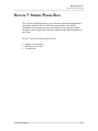
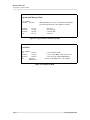
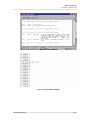
VERIFIER II
User’s Manual
October 1998
HARK SYSTEMS, INC.
2675 Lake Park Drive
N. Charleston, SC 29406
Telephone:
(843) 764-1560
FAX:
(843) 764-3692
Copyright©, 1998 Hark Systems, Inc. All Rights Reserved. Information in this document is subject to change without
notice. No part of this document may be reproduced or transmitted in any form without the express written permission
of Hark Systems, Inc.
Index
Index-1
Hark Systems, Inc.
Verifier II – October 1998
CONTENTS
Contents...............................................................................................................................i
Before You Begin..............................................................................................................iii
How to Use This Manual..................................................................................................iii
Conventions Used in This Manual..................................................................................iii
Section 1: Introduction to the Verifier II........................................................................1
System Features...............................................................................................................2
System Benefits...............................................................................................................2
Section 2: Getting Started.................................................................................................1
2.1 System Requirements.................................................................................................3
2.2 Hardware Installation.................................................................................................3
2.3 Installation Notes.......................................................................................................7
2.4 Logging Onto the Verifier II Application..................................................................8
2.5 Initial Logon State..................................................................................................12
2.6 Logging Off the Verifier II Application..................................................................13
2.7 What To Do Next….................................................................................................14
Section 3: Verifier II Main Menu.....................................................................................1
3.1 Description of the Main Menu...................................................................................3
3.1.1 Menu Options....................................................................................................4
3.2 Selecting Options From the Main Menu....................................................................5
3.2.1 Additional Information...........................................................................................5
3.3 What To Do Next…...................................................................................................6
Section 4: Administrative Functions................................................................................1
4.1 Setting Passwords......................................................................................................2
4.2 Reloading System Defaults........................................................................................4
4.3 Display Expanded Radio Results...............................................................................6
4.4 What To Do Next…...................................................................................................7
Section 5: Scanner Control and Frequency Presets.......................................................1
5.1 Setting Scanner Presets..............................................................................................3
5.2 Manual Frequencies..................................................................................................5
5.3 Radio Volume............................................................................................................7
5.4 Radio Squelch............................................................................................................8
Section 6: Set Current System Time and Date................................................................1
6.1 Set Time and Date Option..........................................................................................3
Section 7: Viewing Paging Data........................................................................................1
7.1 Common Modes.........................................................................................................3
7.1.1 Setting View Mode Parameters..........................................................................3
7.1.2 Selecting a View Mode...........................................................................................5
7.1.3 Pausing the Display................................................................................................8
7.1.4 Hot Keys.................................................................................................................8
Section 8: Search Lists.......................................................................................................1
8.1 Adding Capcodes to Search List................................................................................3
8.2 Deleting Capcodes from Search List.........................................................................4
8.3 Displaying the Capcode Search List..........................................................................4
8.4 Clear Capcode Counts...............................................................................................5
i
Hark Systems, Inc.
Verifier II – October 1998
8.5 Clear Capcode List.....................................................................................................6
8.6 Display/Edit Search Strings.......................................................................................7
8.7 Show Captured Messages..........................................................................................9
8.8 Clear Captured Messages.........................................................................................10
8.9 Enable Auto-Save Capcode.....................................................................................11
Section 9: Viewing Statistics...........................................................................................13
9.1 Displaying the Statistics...........................................................................................15
9.2 Dump Stats...............................................................................................................17
9.3 Clear Stats................................................................................................................18
Appendix A: Warranty Information..............................................................................21
Appendix B: Cancellation...............................................................................................27
Index....................................................................................................................................1
ii
Hark Systems, Inc.
Verifier II – October 1998
BEFORE YOU BEGIN
The purpose of the Verifier II User's Manual is to provide you with the
knowledge needed to efficiently operate the Verifier II equipment and
software. It is recommended that the manual be read before operating the
Verifier II.
The Verifier II consists of a combination of hardware and software uniquely
designed to monitor digital paging formats and decode POCSAG and FLEX
communication protocols. The paging data being transmitted to mobile pagers,
receivers, and beepers can be displayed on most types of RS-232 compatible
terminals. The Verifier II can also be used in conjunction with a computer and
common communications software.
HOW TO USE THIS MANUAL
To help you understand and learn how to use the Verifier II, this manual is
organized in a logical sequence that leads you from the hardware installation
process through login and monitoring of the system.
This User's manual is intended for users of all experience levels. Many general
concepts and simply guidelines are discussed in the initial portions of the
manual. A familiarity with the basic concepts ensures that you can use the
equipment and software efficiently. Subsequent sections describe particular
tasks and list the procedures to accomplish them.
CONVENTIONS USED IN THIS MANUAL
•
The Verifier II software is fully menu driven. The functions performed
within the application are accomplished using the keyboard.
•
Names of keys are shown in capital letters; for example, TAB, SHIFT, and
RETURN.
•
A number or alpha character to the left of the function description identifies
menu functions or options.
•
Certain actions require the simultaneous use of multiple keystrokes. A plus
sign (+) between key names indicates that you press those keys at the same
time. For example, "Press CTRL+A" means that you must hold down the
CTRL key while you press the A key.
iii
Hark Systems, Inc.
Verifier II – October 1998
•
The following keys must be used to move the cursor within a displayed
Verifier II window.
Keys
Function
RETURN
The RETURN key moves the cursor from prompt to prompt
on a displayed window. Upon entering data at a prompt,
press the RETURN key to accept the data and move to the
next prompt.
ESCAPE
The ESCAPE key allows you to exit the displayed window
and return to the prior window.
iv
Hark Systems, Inc.
Verifier II – October 1998
SECTION 1: INTRODUCTION TO THE VERIFIER II
The Hark Verifier II consists of a combination of hardware and software
uniquely designed to monitor digital paging formats and decode POCSAG and
FLEX communication protocols. The Verifier II helps to isolate problems on
paging channels, by allowing users to observe the operation of the paging
channel by displaying either the FLEX or POCSAG paging traffic as it is being
transmitted.
The Verifier II builds and displays statistical information for up to the past 24
hours, which can be used to determine the efficiency of the channel and air
time usage. This statistical information can be converted to comma delineated
format, captured by a PC and terminal program, and then printed. Menu driven
options can be used to isolate a particular paging format, an individual pager
capcode, or a particular message keyword. The Verifier II can follow up to
200 capcodes with "hit-counts" to track pager usage, as well a display and store
the message content of the pages.
The communications receiver is controlled from the Verifier II menu screens.
Hot keys are used to control common functions, such as tuning or selection of
memorized channels.
Communication to the Verifier II is via an RS-232 interface, allowing the use
of computers or dumb terminals for control and operation.
The Verifier II operates in four primary modes during which information can
display:
•
Cap code and Messages Mode – Displays the capcodes and actual content
of messages.
•
Scan Mode – Displays the capcodes and messages that match the entered
scan criteria (including capcodes and search text).
•
Technical Mode – Displays the format and header information.
•
Binary Mode – Displays the raw bitstream (POCSAG only due to the
amount of data to display).
Introduction
I-1
Hark Systems, Inc.
Verifier II – October 1998
System Features
•
Decodes POCSAG 512, 1200, 2400, and FLEX 1600, 3200, 6400 (bi and
quad phase)
•
Interfaced to a Commercial Receiver
•
Serial Port for RS-232 Device, Video Terminal Display, Modem or
Computer Terminal
System Benefits
I-2
•
The Hark Verifier II is a stand-alone decoder that does not require a
computer for decoding.
•
The Verifier II computes internal basic statistics.
•
The Verifier II provides internal decoded page storage.
•
An external PC connection is provided for expanded statistics capabilities.
Introduction
Hark Systems, Inc.
Verifier II – October 1998
SECTION 2: GETTING STARTED
The following is discussed in the following section:
•
•
•
•
Getting Started
System Requirements
Installation Procedures
Logging onto the Verifier II Application
Logging off the Verifier II Application
II-1
Hark Systems, Inc.
Verifier II – October 1998
This page intentionally left blank
II-2
Getting Started
Hark Systems, Inc.
Verifier II – October 1998
2.1 System Requirements
The following equipment represents the minimum hardware configuration of
the Verifier II.
•
•
•
•
•
•
Verifier II Box
ICOM Communications Receiver (IC-PCR1000)
RS-232 Serial Cable
12-14VDC Class 2 Transformer
Antenna
PC Computer or Video Display Terminal
2.2 Hardware Installation
The following section describes the procedure used to install the Verifier 2000.
Refer to Figure 1 for the location of all connections. Note, observe proper
Electro-static discharge (ESD) precautions when handling the equipment and
connecting cables. For example, always touch the back of the scanner first
prior to touching any contacts.
Step 1:
Inspect the shipping packages for damage. If damage is evident,
immediately contact the shipper.
Step 2:
Carefully unpack the Verifier II. Inspect for damages incurred
during shipping.
Step 3:Verify that the following equipment is included in the shipment.
•
•
•
•
Verifier Box
ICOM Communications Receiver
12-14VDC Class 2 Transformer and cable
Antenna
Step 4:Verify that you have obtained the following equipment.
•
•
Getting Started
RS-232 Serial Cable
PC or Dumb Display Terminal (for viewing of data)
II-3
Hark Systems, Inc.
Verifier II – October 1998
Step 5:
Plug one end of the 12-14VDC cable into the connector labeled
12VDC on the back of the Verifier II. Plug the other end of the
12-14VDC cable into the connector labeled DC IN on the
Communications Receiver. These connections are labeled with a
in Figure 1.
Step 6:
Plug one end of the grey cable into the connector labeled SIG at
the back of the Verifier II. Plug the other end of the grey cable
into the connector labeled PACKET (9600bps) on the
communications receiver. These connections are labeled with a
in Figure 1.
Step 7:
Plug the DB-25 connector of the communications cable into the
connector labeled SCANNER at the back of the Verifier II. Plug
the DB-9 connector of the communications cable into the
connector labeled RS-232C on the communications receiver.
These connections are labeled with a in Figure 1.
Step 8:
Plug the DB-25 connector of the RS-232 cable into the connector
labeled RS-232 at the back of the Verifier II. Plug the DB-9
connector of the RS-232 cable into the appropriate port at the back
of the display terminal. This connection is labeled with a in
Figure 1.
Step 9:
Connect the Antenna connector to the port labeled ANT on the
communications receiver. This connection is labeled with a in
Figure 1.
Step 10:
II-4
Plug the Transformer into an electrical outlet.
Getting Started
Hark Systems, Inc.
Verifier II – October 1998
RS-232
SCANNER
PWR
DATA SIG
12VDC
ANT GND DC IN EXT-SP RS-232C PACKET
(96000bps)
ICOM
Communications Receiver
IC-PCR1000
Figure 1 Verifier II/Communications Receiver Connections
Verifier II
Label/Symbol
12VDC /
SIG /
SCANNER /
RS-232 /
Communications
Receiver Label/Symbol
connects
to
connects
to
connects
to
connects
to
Other
Connection
12-14VDC Power
Supply
Audio from scanner
(Grey cable)
RS-232 Serial
Cable
DC IN /
PACKET (9600bps) /
RS-232C /
ANT /
connects to
Cable Type
PC or dumb
terminal port
Antenna
Antenna
Connection
Table 1 Verifier II/Communications Receiver Connections
Getting Started
II-5
Hark Systems, Inc.
Verifier II – October 1998
Step 11:
Turn on the Communications Receiver using the Power Switch
located at the front of the receiver.
Step 12:
If using a software terminal program on a computer, startup the
Windows application. Set the baud rate on the display device to
19.2 K using the following steps.
a.
b.
c.
d.
e.
f.
g.
h.
i.
j.
Select Start from the Windows Desktop.
Select Programs.
Select Accessories.
Select HyperTerminal.
Select Hypertrm.exe.
Enter a name for the new connection (for example,
enter Verifier) and click OK.
Select the appropriate communications port from the
Connect Using field. Click OK.
Select 19200 from the Data bits field. Verify that
Parity equals None, Stop bits equals 1, and Flow
Control equals Hardware. Click OK.
Select the File option, then Save to save the new
configuration. The HyperTerminal screen shown in
Figure 2 displays.
Select the File option, then Exit to exit the
HyperTerminal screen. Select Yes at the Disconnect
Verification prompt.
As a result of the above steps, a shortcut icon is created on the
Accessories screen, allowing you to quickly access the Verifier II
application. Refer to the Logging onto the Verifier II Application
section for complete details on how to access the Verifier II
application.
II-6
Getting Started
Hark Systems, Inc.
Verifier II – October 1998
Figure 2 Verifier HyperTerminal Screen
2.3 Installation Notes
•
RS232 Connection
The Verifier II is configured to connect to a DCE device with a standard
RS-232 (straight through) cable that connects pins 2, 3, and 7 of one
connector to the same pin number of the second connector. If the Verifier
II is connected to a video terminal that is a DTE device, a null RS-232
cable (pins 2 and 3 crossed) must be used.
•
The Verifier II is shipped with an ICOM IC-PCR1000 communications
receiver. The audio is set to demod tones.
•
The Verifier II contains no serviceable parts. If you have any questions,
please contact one of Hark System's Service Technicians.
Getting Started
II-7
Hark Systems, Inc.
Verifier II – October 1998
2.4 Logging Onto the Verifier II Application
Perform the following steps to log onto the Verifier II application.
Step 1:
Turn on the Communications Receiver using the Power Switch
located at the front of the receiver.
Step 2:
Access the Windows Desktop from the terminal attached to the
Verifier II equipment.
Step 3:
Select Start from the Windows Desktop. The Start Pulldown
Menu displays.
Step 4:
Select Programs from the Start Pulldown Menu. The Programs
Pulldown Menu displays.
Step 5:
Select Accessories from the Programs Pulldown Menu. The
Accessories Pulldown Menu displays.
Step 6:
Select HyperTerminal from the Accessories Pulldown Menu. The
C\:Program Files\Accessories window displays.
Figure 3 C:\Program Files\Accessories Window
Step 7:
II-8
Select the Verifier.ht icon. The Verifier – HyperTerminal screen
displays.
Getting Started
Hark Systems, Inc.
Verifier II – October 1998
Figure 4 Verifier – HyperTerminal Screen
Step 8:
Press the ENTER key on the terminal's keyboard. The Login screen
displays.
Figure 5 Login Screen
Getting Started
II-9
Hark Systems, Inc.
Verifier II – October 1998
Step 9:
Press the SPACE BAR on the terminal's keyboard. The Password
Prompt screen displays.
Figure 6 Password Prompt Screen
Step 10:
Key the appropriate password at the Enter Operator Password
prompt and press the ENTER key.
•
If logging onto the Verifier II application for the first time after
installation, enter one of the following three default factory
passwords at the prompt. The following passwords allow you
to access the Main Menu. Once the Main Menu displays, you
should change the default passwords using the Administration
option provided on the Main Menu. Refer to Section 6 for
details.
The following three default passwords represent three levels of
access.
GUEST – Entering GUEST at the Enter Operator Password
prompt allows you to view statistics, capcode hit counts, and
adjust the current system date and time. You cannot access
any of the other functions provided by the Verifier II
application.
II-10
Getting Started
Hark Systems, Inc.
Verifier II – October 1998
TECH – Entering TECH at the Enter Operator Password
prompt allows you to perform all functions with the exception
of those provided within the Administration option. You may
not edit passwords, load default parameters, or enable or
disable expanded radio setting responses.
ADMIN – Entering ADMIN at the Enter Operator Password
prompt allows you to access all functions provided within the
Verifier II application. This is the only password that allows
you to edit passwords, load default parameters, and enable or
disable expanded radio setting responses.
•
If you have already changed the default factory passwords,
enter the current system password that is appropriate for your
access level at the Enter Operator Password prompt and press
the ENTER key.
NOTES
The Main Menu does not vary; all options display whether you
logon as GUEST, TECH, or ADMIN. However, particular
options displayed on the Main Menu are not accessible
depending upon your access level. If you select an option to
which you do not have access, the Main Menu continues to
display and no further processing occurs.
The passwords are case-sensitive. Both the default factory
passwords and your individualized system password must be
entered in the proper case. For example, the default password of
GUEST must be entered in upper case. Also, if the password is a
combination of upper and lower cases, such as RgET02aA, the
password must be entered in exactly that combination of upper
and lower case characters. If entered in any other combination of
upper and lower cases, you are not logged onto the application.
Step 11:
Getting Started
The entered password is verified at this time. If correct, a
Welcome message displays, then the Verifier II Main Menu
displays. The Main Menu provides you with the ability to access
all the Verifier II functions.
II-11
Hark Systems, Inc.
Verifier II – October 1998
Figure 7 Main Menu
Step 12:
Select an option from the Main Menu by keying the number
displayed to the left of each option at the Enter Command prompt
and pressing the ENTER key. For example, to access the View
Mode option, key a 1 at the Enter Command prompt and press the
ENTER key. Refer to Section 3 of this manual for details on using
the Main Menu.
2.5 Initial Logon State
Upon logging onto the Verifier II application, the Verifier sets the
communications receiver to the last used channel, volume, and squelch. The
unit is in a No Menu state. In this mode, you are notified of any automatic
frequency centering, captured pages, and if enabled, captured messages.
II-12
Getting Started
Hark Systems, Inc.
Verifier II – October 1998
Hot keys are functional in the No Menu state. Hot keys include the following:
•
CTRL+A through CTRL+T select one of the 20 preset frequencies. Refer to
Section 5.1 for a complete listing of preset frequencies.
•
CTRL+X toggles you between auto and manual frequency tracking.
•
CTRL+Z shows the current frequency and signal level on the Scanner Menu.
•
The plus (+) and minus (-) keys, shifted or unshifted, control the speaker
volume.
•
The < and > keys adjust the frequency in 100 Hz increments.
•
The comma (,) and period (.) keys adjust the squelch setting. Note, the
squelch setting only affects the speaker.
•
Pressing the SPACE BAR returns you to the Password prompt.
Selecting the corresponding option from the Main Menu can also access each
of the above processes. Refer to the following sections of this manual for a
complete discussion of each option.
2.6 Logging Off the Verifier II Application
Log off the Verifier II application by performing the following.
Step 1:
Exit any of the displayed Verifier II screens by pressing the Escape
key until you access the Main Menu.
Step 2:
Select the File option displayed in the Menu Bar at the top of the
Main Menu. The File Pulldown menu displays.
Step 3:
Select the Exit option from the File Pulldown menu. The
Disconnect Verification window displays.
Figure 8 Disconnect Verification Window
Getting Started
II-13
Hark Systems, Inc.
Verifier II – October 1998
Step 4:
Select Yes to exit the Verifier II application. Select No to
terminate the exit process and remain within the Verifier II
application.
2.7 What To Do Next…
Now that the system has been installed and you have successfully logged onto
the Verifier II application, you should refer to Section 3, Verifier II Main
Menu, to learn about the Main Menu and the various utilities that can be
accessed from the Main Menu.
II-14
Getting Started
Hark Systems, Inc.
Verifier II – October 1998
SECTION 3: VERIFIER II MAIN MENU
The following is discussed within Section 3.
•
•
•
Main Menu
Verifier II Main Menu
Various options and utilities that you may access from the Main Menu
Procedure used to select the menu options from the Main Menu
III-1
Hark Systems, Inc.
Verifier II – October 1998
This page intentionally left blank
III-2
Main Menu
Hark Systems, Inc.
Verifier II – October 1998
3.1 Description of the Main Menu
The Verifier II Main Menu displays automatically as a result of the successful
completion of the login process. The Main Menu provides you with the ability
to access all of the Verifier II utilities and functions.
Status Bar
Menu Options
Figure 9 Verifier II Main Menu
The Status Bar identifies the application (Verifier II), the software version that
is currently being used (Ver: 01.XX, where XX identifies the actual version),
and the software build date (for example, 09-30-1998).
Main Menu
III-3
Hark Systems, Inc.
Verifier II – October 1998
3.1.1 Menu Options
The following menu options display on the Main Menu. Selection of an option
initiates the corresponding utility. The appropriate display window or entry
prompts display. Each of the following options are discussed in detail in
Sections 4 through 9 of this manual.
III-4
View Mode
The View Mode option allows you to set the parameters
used to view decoded information and allows you to
begin viewing the decoded information. Four common
view modes are provided; you may selectively change
the parameters within each of the modes.
Search Menu
The Search Menu option allows you to identify the
search criteria for the capcodes and messages that you
want to view, and allows you to view the actual
capcodes and messages. You identify the capcode or
search string for which you want to search. The
Verifier II displays the matching capcode list, hit
counts, messages with matching search strings, etc.
Stats Menu
The Stats Menu option allows you to view the current
and last 23 hours of statistics that were captured, view
the last 23 hours of statistics in Comma Delineated
Format, and clear the statistics and reset the counts to
zero.
Administration
The Administration option allows you to change
passwords, reload the original parameters and stats, and
display expanded radio results or information.
Scanner Functions
The Scanner Functions option allows you to set the
scanner radio volume and squelch, plus control the
scanner frequency presets.
Set Time and Date
The Set Time and Date option allows you to set the
current system time and date.
Main Menu
Hark Systems, Inc.
Verifier II – October 1998
3.2 Selecting Options From the Main Menu
Select an option displayed on the Main Menu by performing the following.
1.
Key the number that is displayed to the left of the Menu option at the
Enter Command prompt.
For example, to access the View Mode option, key a 1 at the Enter
Command prompt. To access the Administration option, key a 4 at the
Enter Command prompt.
2.
Press the ENTER key.
The selected option initiates the appropriate utility. The corresponding
screen or prompts display. Note, if an invalid entry is keyed at the Enter
Command prompt, or you enter an option for which you do not have
access authority, the option is not accepted and no further processing takes
place until you enter a valid option.
3.2.1 Additional Information
To return to a prior menu, press the ESCAPE key.
When prompted to enter data from the command line, particular keys perform
the following functions.
Key
Function
<BACKSPACE> Erases the previous character.
<RUB>
<DELETE>
<ESC>
<ENTER>
Main Menu
Erases all the characters entered at the prompt.
Indicates that data entry is complete and to initiate the
corresponding option or data entry process.
III-5
Hark Systems, Inc.
Verifier II – October 1998
3.3 What To Do Next…
You are now ready to configure the Verifier II application. You should first
change the factory default passwords to your own, individualized passwords
using the Administration option. Once the passwords have been changed, you
can set the scanner preset frequencies, radio volume, radio squelch, and current
system date and time, as required. Refer to Section 4 through 6 for complete
details.
III-6
Main Menu
Hark Systems, Inc.
Verifier II – October 1998
SECTION 4: ADMINISTRATIVE FUNCTIONS
The following section discusses the administrative functions that can be
performed within the Verifier II application.
•
•
•
Changing Passwords
Loading Default Parameters and Stats
Displaying Expanded Radio Results
The above functions are accessed as a result of selecting the Administration
option provided on the Main Menu. Please note, only those users who have
logged onto the Verifier II application using the Administrative password have
access to this functionality.
Administrative Functions
IV-1
Hark Systems, Inc.
Verifier II – October 1998
4.1 Setting Passwords
The Verifier II application provides you with the ability to change the factory
default passwords used while logging onto the Verifier II application. In
addition, you may change your individualized password at any time.
NOTE:
It is highly recommended that you change the factory default passwords
originally assigned by Hark as soon as you have installed and initialized the
application. Refer to Section 2.4 for complete details on the default
passwords. It is also recommended that you change your individualized
passwords on a regular basis.
Perform the following steps to access the Password Menu screen and change a
password.
1.
Select the Administration option displayed on the Main Menu by keying a
4 at the Enter Command prompt.
The Administration Menu displays.
Figure 10 Administration Menu
IV-2
Administrative Functions
Hark Systems, Inc.
Verifier II – October 1998
2.
Select the Setup Passwords option by keying a 1 at the Enter Command
prompt.
The Password Menu displays.
Figure 11 Password Menu
3.
Select the password that requires changing by entering the number
displayed next to the password level that requires changing at the Enter
Command prompt. For example, to change the Admin password, key a 1
at the Enter Command prompt.
The Password: prompt displays.
Administrative Functions
IV-3
Hark Systems, Inc.
Verifier II – October 1998
Figure 12 Password Prompt
4.
Key the new password at the Password prompt and press the ENTER key.
Note that passwords are case-sensitive.
The Password Menu redisplays.
5.
Continue changing the passwords as required, or press the Escape key to
return to the Administration and Main Menus.
4.2 Reloading System Defaults
The Reload Defaults option provided on the Administration Menu allows you
to reset your view parameters to the defaults originally set by Hark Systems
and clear any statistical data and counts. The current view parameters can be
viewed and changed using the View Menu option referenced on the Verifier II
Main Menu.
Perform the following steps to access the Reload Defaults option and change
the parameters back to the system defaults.
1.
Select the Administration option displayed on the Main Menu by keying a
4 at the Enter Command prompt.
The Administration Menu displays.
IV-4
Administrative Functions
Hark Systems, Inc.
Verifier II – October 1998
2.
Select the Reload Defaults option by keying a 2 at the Enter Command
prompt.
The Reload Defaults and Clear Statistics Verification prompt displays.
Figure 13 Reload Defaults and Clear Statistics Verification Prompt
3.
Enter a Y at the Do You Want to Load Defaults and Clear Statistics
prompt and press the ENTER key to continue to reload the defaults and clear
the statistics. Enter a N at the prompt and press the ENTER key if you no
longer want to reload the defaults and clear the statistics.
In either of the above cases, the Administration Menu is redisplayed.
Press the Escape key to return to the Main Menu.
Administrative Functions
IV-5
Hark Systems, Inc.
Verifier II – October 1998
4.3 Display Expanded Radio Results
The Enable Expanded Radio Results option provided on the Administration
Menu allows you to display expanded radio results or information when
changing the frequency, volume, and squelch settings while in view mode.
Exanded radio results include the frequency to which the scanner is adjusted
and the volume and squelch to which the scanner is set. Once the functionality
is enabled, the functionality can be disabled at any time.
Perform the following to display expanded radio results.
1.
Select the Administration option displayed on the Main Menu by keying a
4 at the Enter Command prompt.
The Administration Menu displays.
2.
Select the Enable Expanded Radio Results option by keying a 3 at the
Enter Command prompt.
The Administration Menu is redisplayed; the Disable Expanded Radio
Results option now displays, indicating that the expanded radio results
functionality has been enabled.
The option acts as a toggle. To disable the expanded radio results
functionality, simply select the Disable Expanded Radio Results option.
The functionality is disabled and the Enable Expanded Radio Results
option displays.
3.
IV-6
To view the exanded radio results, access one of the four view modes as
discussed in Section 7.
• Adjust the frequency by pressing the < or > key. The literal
"Frequency adjusted to xxxxxxxxx" displays, where xxxxxxxxxx
equals the actual frequency setting, while the expanded radio results
functionality is enabled. The literal "Frequency adjusted" (without the
frequency setting) displays if the expanded radio results functionality
is disabled.
Administrative Functions
Hark Systems, Inc.
Verifier II – October 1998
•
•
Adjust the squelch by pressing the period (.) and cooma (,) keys. The
literal "Squelch set to xx" displays, where xx equals the squelch
setting, while the exanded radio results functionality is enabled. The
literal "Squelch set" (without the squelch setting) displays if the
exanded radio results functionality is disabled.
Adjust the volume by pressing the plus (+) and minus (-) keys. The
literal "Volume set to xx" displays, where xx equals the volume
setting, while the exanded radio results functionality is enabled. The
literal "Volume set" (without the volume setting) displays if the
exanded radio results functionality is disabled.
4.4 What To Do Next…
Continue to Section 5 to set up to 20 scanner preset frequencies, plus control
the scanner volume and squelch.
Administrative Functions
IV-7
Hark Systems, Inc.
Verifier II – October 1998
This page intentionally left blank
IV-8
Administrative Functions
Hark Systems, Inc.
Verifier II – October 1998
SECTION 5: SCANNER CONTROL AND FREQUENCY
PRESETS
Section 5 discusses the following functionality.
•
•
•
•
Setting up to 20 preset scanner frequencies
Setting and viewing the current scanner frequency
Setting the radio volume
Setting the squelch volume
The above functions are accessed as a result of selecting the Scanner
Functions option provided on the Main Menu. Please note, only those users
who have logged onto the Verifier II application using the Technician and
Administrative password have access to this functionality.
Scanner Control and Frequency Presets
V-1
Hark Systems, Inc.
Verifier II – October 1998
This page intentionally left blank
V-2
Scanner Control and Frequency Presets
Hark Systems, Inc.
Verifier II – October 1998
5.1 Setting Scanner Presets
The Verifier II application provides you with the ability to preset up to 20
scanner frequencies. This functionality is accessed via the Scanner Functions
option provided on the Main Menu.
Perform the following to preset up to 20 scanner frequencies.
1.
Select the Scanner Functions option displayed on the Main Menu by
keying a 5 at the Enter Command prompt.
The Scanner Menu displays. Note, the current frequency to which the
scanner is set and the current signal strength displays on this screen.
Figure 14 Scanner Menu
2.
Select the Set Scanner Presets option by keying a 1 at the Enter
Command prompt.
The Scanner Preset Menu displays.
Scanner Control and Frequency Presets
V-3
Hark Systems, Inc.
Verifier II – October 1998
Figure 15 Scanner Preset Menu
3.
To add a new preset frequency, key the letter corresponding to the first
preset frequency that is equal to 0. In the above example, key an A at the
Enter Command prompt. To edit an existing preset frequency, key the
letter corresponding to the preset frequency that needs to be changed.
The Enter Frequency prompt displays.
Figure 16 Enter Frequency Prompt
V-4
Scanner Control and Frequency Presets
Hark Systems, Inc.
Verifier II – October 1998
4.
Enter the frequency using the following format and press the ENTER key.
GM.. The first four characters represent the gigahertz and megahertz.
K..
The next three characters represent the kilohertz.
H..
The last three characters represent the hertz.
The Scanner Preset Menu redisplays, allowing you to continue entering or
changing preset scanner frequencies. Press the ESCAPE key to return to the
Scanner and Main Menus.
You may select any of the 20 preset frequencies while in View mode by
using the CTRL+A through CTRL+T hot keys. Refer to Section 7 for details.
5.2 Manual Frequencies
You may manually set the scanner frequency using the Manual Frequency
option provided on the Scanner Menu.
Perform the following to manually set the scanner frequency.
1.
Select the Scanner Functions option displayed on the Main Menu by
keying a 5 at the Enter Command prompt.
The Scanner Menu displays.
2.
Select the Manual Frequency option by keying a 2 at the Enter
Command prompt. Note, the current frequency displays next to the
Manual Frequency option. In the example shown in the following
screen, the frequency is set to 158700000.
The Enter Frequency prompt displays.
Scanner Control and Frequency Presets
V-5
Hark Systems, Inc.
Verifier II – October 1998
Figure 17 Enter Frequency Prompt
3.
Enter the frequency using the following format and press the ENTER key.
GM.. The first four characters represent the gigahertz and megahertz.
K..
The next three characters represent the kilohertz.
H..
The last three characters represent the hertz.
The Scanner Menu redisplays. Press the ESCAPE key to return to the Main
Menu.
Note, the frequency can also be adjusted while in View mode using the < and >
hot keys.
•
•
Each time you press the < key while in view mode reduces the frequency
setting by 100.
Each time you press the > key while in view mode increases the frequency
setting by 100.
Refer to Section 7 for details.
V-6
Scanner Control and Frequency Presets
Hark Systems, Inc.
Verifier II – October 1998
5.3 Radio Volume
You may manually set the radio volume of the scanner using the Radio
Volume option provided on the Scanner Menu.
Perform the following to manually set the radio volume.
1.
Select the Scanner Functions option displayed on the Main Menu by
keying a 5 at the Enter Command prompt.
The Scanner Menu displays.
2.
Select the Radio Volume option by keying a 3 at the Enter Command
prompt.
The Set Volume prompt displays, with the current setting displayed at the
end of the prompt. In the example shown in the following figure, the
volume is set at 90.
Figure 18 Set Volume Prompt
3.
Enter the volume setting at the Enter Value for Volume prompt and press
the ENTER key. Valid entries are within the range of 0 through 255, with
zero being the lowest volume and 255 being the highest volume.
Scanner Control and Frequency Presets
V-7
Hark Systems, Inc.
Verifier II – October 1998
The Scanner Menu redisplays. Press the ESCAPE key to return to the Main
Menu.
Note, the volume setting can also be set and adjusted using the plus (+) and
minus keys (-) hot keys while in view mode.
•
•
Each time you press the + key while in view mode increases the scanner
volume setting by 2 increments.
Each time you press the - key while in view mode decreases the scanner
squelch volume by 2 increments.
Refer to Section 7 for details.
5.4 Radio Squelch
You may manually set the radio squelch of the scanner using the Radio
Squelch option provided on the Scanner Menu.
Perform the following to manually set the radio squelch.
1.
Select the Scanner Functions option displayed on the Main Menu by
keying a 5 at the Enter Command prompt.
The Scanner Menu displays.
2.
Select the Radio Squelch option by keying a 4 at the Enter Command
prompt.
The Set Squelch prompt displays, with the current setting displayed at the
end of the prompt. In the example shown in the following figure, the
squelch is set at 32.
V-8
Scanner Control and Frequency Presets
Hark Systems, Inc.
Verifier II – October 1998
Figure 19 Set Squelch Prompt
3.
Enter the squelch setting at the Enter Value for Squelch prompt and press
the ENTER key. Valid entries are within the range of 0 through 255, with
zero being the minimum suppression and 255 being the maximum
suppression.
The Scanner Menu redisplays. Press the ESCAPE key to return to the Main
Menu.
Note, the squelch setting can also be set and adjusted using the comma (,) and
period (.) hot keys while in view mode.
•
•
Each time you press the comma key while in view mode reduces the
squelch setting by 2 increments.
Each time you press the period key while in view mode increases the
squelch setting by 2 increments.
Refer to Section 7 for details.
Scanner Control and Frequency Presets
V-9
Hark Systems, Inc.
Verifier II – October 1998
This page intentionally left blank
V-10
Scanner Control and Frequency Presets
Hark Systems, Inc.
Verifier II – October 1998
SECTION 6: SET CURRENT SYSTEM TIME AND DATE
The following section describes the process that must be followed to set the
current system time and date.
All levels of users may access this functionality.
System Time and Date
VI-1
Hark Systems, Inc.
Verifier II – October 1998
This page intentionally left blank
VI-2
System Time and Date
Hark Systems, Inc.
Verifier II – October 1998
6.1 Set Time and Date Option
During system configuration, you must set the system time and date referenced
by the Verifier II application to the current time and date.
Perform the following to set the system time and date.
1.
Select the Set Time and Date option displayed on the Main Menu by
keying a 6 at the Enter Command prompt.
The Date Menu displays.
Figure 20 Date Menu
2.
Key the number displayed to the left of the date or time parameter that you
want to change at the Enter Command prompt. For example, to change
the month, key a 1 at the Enter Command prompt.
The corresponding prompt displays. For example, if changing the month,
the Enter Month prompt displays.
3.
Enter the appropriate information at the prompt and press the ENTER key.
For example, if changing the month, enter 10 to change the system month
to October (10th month within the year).
System Time and Date
VI-3
Hark Systems, Inc.
Verifier II – October 1998
4.
5.
Repeat Steps 2 and 3 until all parameters within the system date and time
have been set.
Press the ESCAPE key after all required changes have been made.
The Main Menu redisplays.
VI-4
System Time and Date
Hark Systems, Inc.
Verifier II – October 1998
SECTION 7: VIEWING PAGING DATA
The Verifier II application allows you to monitor a particular paging channel
and display either the FLEX or POCSAG paging traffic as it is being
transmitted. This functionality may be accessed by users who have logged
onto the Verifier II application using the Technician and Administration level
passwords.
Section 7 discusses the following processes.
•
•
•
Setting view parameters
Selecting a view mode
Viewing data
Viewing Paging Data
VII-1
Hark Systems, Inc.
Verifier II – October 1998
This page intentionally left blank
VII-2
Viewing Paging Data
Hark Systems, Inc.
Verifier II – October 1998
7.1 Common Modes
Pages may be viewed in one of four common modes. These common modes
include:
•
Cap code and Messages Mode – Displays the capcodes and actual content
of messages.
•
Scan Mode – Displays the capcodes and messages that match the entered
scan criteria (including capcodes and search text).
•
Technical Mode – Displays the format and header information.
•
Binary Mode – Displays the raw bitstream (POCSAG only due to the
amount of data to display).
The view mode in which the messages are to be displayed is selected using the
View Mode option provided on the Main Menu.
Particular parameters or message formats are associated with each of these
common modes. The parameters associated with each of the view modes may
be viewed and edited using the View Mode option.
7.1.1 Setting View Mode Parameters
The parameters associated with a particular view mode determine the type of
pages that are displayed for viewing, plus determine the type of information
displayed for each of the pages.
Default parameters are associated with each of the four view modes; these
default parameters may be changed using the following steps.
1.
Select the View Mode option displayed on the Main Menu by keying a 1
at the Enter Command prompt.
The View Mode Menu displays.
Viewing Paging Data
VII-3
Hark Systems, Inc.
Verifier II – October 1998
The View Mode Menu is divided into two areas:
Mode Options Area – This area lists the four view modes that may be
selected. The parameters associated with each of the modes are displayed
in the Options column to the right of the mode listing.
Toggle Options Area – This area lists each of the parameters that may be
associated with a particular mode and the associated formats. A particular
parameter may be enabled or disabled, depending upon the paging data
that you want to view. If the parameter is preceded by the term "Disable",
the parameter is currently enabled (for example, Disable Alpha Pages). If
the parameter is preceded by the term "Enable", the parameter is currently
disabled (for example, Enable Expanded).
Figure 21 View Mode Menu
2.
VII-4
To enable a particular parameter that is currently disabled, key the alpha
character displayed to the left of the parameter in the Enter Command
prompt. For example, to enable the Raw Mode shown in the above figure,
key a R at the Enter Command prompt.
Viewing Paging Data
Hark Systems, Inc.
Verifier II – October 1998
3.
To disable a particular parameter that is currently enabled, key the alpha
character displayed to the left of the parameter in the Enter Command
prompt. For example, to disable the viewing of Alpha Pages shown in the
above figure, key an A at the Enter Command prompt.
4.
To begin viewing the pages, key a V at the Enter Command prompt.
7.1.2 Selecting a View Mode
Once you have set your parameters, you may select a view mode in which you
want to view the paging data being decoded.
Perform the following steps to view the paging data.
1.
Select the View Mode option displayed on the Main Menu by keying a 1
at the Enter Command prompt.
The View Mode Menu displays.
2.
Select the appropriate view mode by keying the number displayed to the
left of the mode at the Enter Command prompt.
The literal "View Enabled" displays. The data begins to display according
to the parameters set for the selected view mode. Refer to the following
figures for samples of captured messages. Press the ESCAPE key at any
time to exit the View mode and return to the Main Menu.
•
Figure 22 shows an example of the data displayed if the Capcode and
Message Mode option (Option 1) is selected.
•
Figure 23 shows an example of the data displayed if the Scan Mode
option (Option 2) is selected.
•
Figure 24 shows an example of the data displayed if the Technical
Mode option (Option 3) is selected.
•
Figure 25 shows an example of the data displayed if the Binary Mode
(POCSAG) option (Option 4) is selected.
3.
Press the ESCAPE key to exit the view mode and return to the Main
Menu.
Viewing Paging Data
VII-5
Hark Systems, Inc.
Verifier II – October 1998
Capcode and Message Mode
View Enabled
POCSAG: 0079008
POCSAG:
POCSAG:
POCSAG:
Flex:
MRS GREENE 921-1111 PT: JOSEPH CHILDES REC
DR: BLACKE PLEASE CALL WARD AT ONCE
1271111
1177888
1155222
1133211
222-3344
912-4402-888
CALL HOME
332-4444
Figure 22 Sample Capcode and Message Mode
Scan Mode
View Enabled
Flex:
0124567
POCSAG:
1133224
POCSAG:
3344556
Flex:
2255345
BIRTHDAY
CALL OFFICE NOW!
CALL YOUR WIFE ASAP AT 555-7777
CALL 2223344; SEMI-EMERGENCY
WANT TO REMIND YOU ITS MOM'S
Figure 23 Sample Scan Mode
VII-6
Viewing Paging Data
Hark Systems, Inc.
Verifier II – October 1998
Figure 24 Technical Mode
Figure 25 Binary Mode (POCSAG)
Viewing Paging Data
VII-7
Hark Systems, Inc.
Verifier II – October 1998
7.1.3 Pausing the Display
The display of messages may be paused at any time by pressing the <SPACE
BAR> while in View mode. While in pause, the data is still being captured; the
messages are simply not displayed. Press any key to unpause the display and
begin displaying the captured messages.
Note, the display must not be paused for a long period of time; doing so causes
the buffer to fill and over-run, causing invalid data to be displayed.
7.1.4 Hot Keys
The following hot keys are functional while you are in any of the four view
modes.
Keys
CTRL+A to T
CTRL+X
CTRL+Z
Plus (+)
Minus (-)
Comma (,)
Period (.)
<
>
VII-8
Function
Selects the preset frequency. (Refer to Section 5.1 for details.)
Toggles you between auto and manual frequency tracking.
Shows the current frequency setting and signal level.
Increases the speaker volume by 2 increments.
Decreases the speaker volume by 2 increments.
Reduces the squelch setting by 2 increments.
Increases the squelch setting by 2 increments.
Decreases the frequency setting by 100.
Increases the frequency setting by 100.
Viewing Paging Data
Hark Systems, Inc.
Verifier II – October 1998
SECTION 8: SEARCH LISTS
The Verifier II application allows you to search for:
•
•
Any pages initiated by a particular capcode.
Any messages containing a specified search string.
This section discusses the processes used to search for pages which reference a
particular cap code and/or search string, display and view the capcode list and
messages, clear the capcode counts, and delete the captured messages.
Appendix B
B-1
Hark Systems, Inc.
Verifier II – October 1998
This page intentionally left blank
B-2
Appendix B
Hark Systems, Inc.
Verifier II – October 1998
8.1 Adding Capcodes to Search List
By adding a particular capcode to the Search List, those pages referencing the
specified capcode are isolated and displayed in a capcode listing. Capcodes
are added to the search list using the Search Menu option provided on the
Main Menu.
Perform the following steps to add capcodes to the search list.
1.
Select the Search Menu option from the Main Menu by keying a 2 at the
Enter Command prompt.
The Search Menu displays.
Figure 26 Search Menu
2.
Select the Enter Search Capcode option by keying a 1 at the Enter
Command prompt.
The Enter Capcode to Search prompt displays.
3.
Enter the digits comprising the capcode for which you want to display the
pages at the Enter Capcode to Search prompt and press the ENTER key.
The Search Menu displays. The capcode is added to the search list.
Appendix B
B-3
Hark Systems, Inc.
Verifier II – October 1998
8.2 Deleting Capcodes from Search List
You have the ability to delete a particular capcode from the search list if you
no longer want to view and track the pages sent by that capcode. Capcodes are
deleted from the search list using the Delete Search Capcode option provided
on the Search Menu. Note, if you want to delete all the capcodes from the
search list, use the Clear Capcode List option discussed in Section 8.5.
Perform the following steps to delete capcodes from the search list.
1.
Select the Search Menu option from the Main Menu by keying a 2 at the
Enter Command prompt.
The Search Menu displays.
2.
Select the Delete Search Capcode option by keying a 2 at the Enter
Command prompt.
The Enter Capcode to Delete prompt displays.
3.
Key the digits comprising the capcode that needs to be deleted from the
search list at the Enter Capcode to Delete prompt and press the ENTER key.
The Search Menu redisplays. The capcode is deleted from the search list.
8.3 Displaying the Capcode Search List
You may display a listing of capcodes currently referenced in the search list.
(Any pages referencing the capcodes listed in the search list are captured
displayed as a result of selecting the Show Captured Messages option on the
Search Menu.)
Perform the following steps to display the capcodes referenced in the search
list.
1.
Select the Search Menu option from the Main Menu by keying a 2 at the
Enter Command prompt.
The Search Menu displays.
2.
B-4
Select the Display Capcode List option by keying a 3 at the Enter
Command prompt.
Appendix B
Hark Systems, Inc.
Verifier II – October 1998
The Capcode Listing displays.
Figure 27 Capcode List
3.
Press the ENTER key to return to the Search Menu.
8.4 Clear Capcode Counts
The Verifier II application keeps a count of the number of pages which
reference each of the capcodes listed in the search list. You have the ability to
reset these counts to zero (0) using the Clear Capcode Counts option provided
on the Search Menu.
Appendix B
B-5
Hark Systems, Inc.
Verifier II – October 1998
Perform the following to reset the capcode counts to zero.
1.
Select the Search Menu option from the Main Menu by keying a 2 at the
Enter Command prompt.
The Search Menu displays.
2.
Select the Clear Capcode Counts option by keying a 4 at the Enter
Command prompt.
The Do You Want to Clear ALL Capcode Counts prompt displays.
3.
Key a Y at the prompt and press the ENTER key to reset all the capcode
counts to zero.
Key a N at the prompt and press the ENTER key if you no longer want to
reset the capcode counts to zero.
In either of the above cases, the Search Menu redisplays.
8.5 Clear Capcode List
You have the option to conveniently delete all search capcodes from the search
list using the Clear Capcode List option provided on the Search Menu.
Perform the following steps to delete all capcodes from the search list.
1.
Select the Search Menu option from the Main Menu by keying a 2 at the
Enter Command prompt.
The Search Menu displays.
2.
Select the Clear Capcode List option by keying a 5 at the Enter Command
prompt.
The Do You Want to Delete ALL Capcodes prompt displays.
3.
B-6
Key a Y at the prompt and press the ENTER key to delete all the capcodes
from the search list.
Appendix B
Hark Systems, Inc.
Verifier II – October 1998
Key a N at the prompt and press the ENTER key if you no longer want to
delete all the capcodes from the search list.
In either of the above cases, the Search Menu redisplays.
8.6 Display/Edit Search Strings
You have the ability to search for a particular string of characters within
messages. If the specified search string is encountered, the message is
displayed for viewing. Up to 20 search strings may be specified. New search
strings may be added, and existing search strings may be changed or deleted at
any time.
Perform the following steps to add new search strings and view and edit
existing search strings.
1.
Select the Search Menu option from the Main Menu by keying a 2 at the
Enter Command prompt.
The Search Menu displays.
2.
Select the Display/Edit Search Strings option by keying a 6 at the Enter
Command prompt.
The Search String Menu displays. Any existing search strings are listing.
In the example shown in the following screen, any messages containing
the word "CALL" are selected and displayed for viewing.
Appendix B
B-7
Hark Systems, Inc.
Verifier II – October 1998
Figure 28 Search String Menu
3.
To add a new search string, key the alpha character for the first blank line
at the Enter Command prompt. In the example shown in the above screen,
key a B at the prompt to enter the search string on the second detail line.
To edit a particular search string, key the alpha character corresponding to
the detail line on which the search string is displayed at the Enter
Command prompt. In the example shown in the above screen, key an A at
the prompt to edit the "CALL" search string.
The Enter Search String prompt displays.
4.
5.
B-8
Key the new search string at the Enter Search String prompt and press the
ENTER key. Note, a question mark (?) matches any single character.
Spaces are allowed and must be matched. Searches are not case sensitive.
•
If editing an existing search string, the new search string replaces the
prior search string.
•
If adding a new search string, the new search string displays on the
corresponding detail line.
Press the ESCAPE key to return to the Search Menu. The Verifier II beeps
whenever a message contains one or more of the indicated search strings.
Appendix B
Hark Systems, Inc.
Verifier II – October 1998
The messages are stored in the internal memory and can be viewed using the
Show Captured Messages option discussed in the following section.
8.7 Show Captured Messages
The Show Captured Messages option provided on the Search Menu allows
you to view the contents of captured messages. A message is captured if either
the capcode referenced in the message matches a capcode referenced in the
search list, or a character string in the message matches one of the search
strings.
Perform the following steps to view the contents of the captured messages.
1.
Select the Search Menu option from the Main Menu by keying a 2 at the
Enter Command prompt.
The Search Menu displays. As messages are captured, the amount of
message memory being used, the percentage of message memory being
used, and the number of captured messages displays below the Show
Captured Messages option. Refer to Figure 27 for the location of this
information.
2.
Select the Show Captured Messages option by keying a 7 at the Enter
Command prompt.
The Enter Capcode to Display or <CR> for All prompt displays.
3.
If you only want to view the messages that reference a particular capcode,
enter the capcode at the Enter Capcode to Display or <CR> for All
prompt and press the ENTER key.
If you want to view all messages, regardless of the capcode, simply press
the ENTER key while the prompt is displayed.
In either of the above cases, the appropriate messages are displayed.
Refer to the following figure for a sample. The receiving capcode, page
type, date and time page was sent, and contents of the message are listed.
Appendix B
B-9
Hark Systems, Inc.
Verifier II – October 1998
2055544 P
0077999 P
10/02
10/02
02:02:28
02:07:43
1405555 P
10/02
02:08:09
0188888 P
1133454 F
10/02
10/02
02:50:46
02:53:34
[CALL YOUR WIFE ASAP AT 555-6666 ]
[MRS WHYTRIE 445-6677 PT: JAMES
GREENE REG DR : JURRIE PLEASE
CALL HOSPITAL FOR ADMITTANCE]
[PLEASE CALL JAN @432-1234 RE:
PHONE LINES]
[PLEASE CALL 888-9090]
[CALL FRONT OFFICE AT YOUR
CONVENIENCE]
Hit any key to continue._
Figure 29 Sample Captured Messages
4.
Press the ENTER key to view any additional messages not displayed on the
current screen. The message "End of Messages" displays once all
captured messages have been displayed.
5.
Press any key to return to the Search Menu.
8.8 Clear Captured Messages
Once you have reviewed the captured messages, the messages can be cleared
from internal memory using the Clear Captured Messages option provided on
the Search Menu. Note, once the messages are cleared using this option, you
can no longer view those messages. This function should be performed on a
periodic basis to ensure that the memory does not become overloaded. The
actual amount of memory being used for captured messages displays on the
Search Menu under the Show Captured Messages option.
Perform the following steps to clear any captured messages.
1.
Select the Search Menu option from the Main Menu by keying a 2 at the
Enter Command prompt.
The Search Menu displays.
2.
B-10
Select the Clear Captured Messages option by keying an 8 at the Enter
Command prompt.
Appendix B
Hark Systems, Inc.
Verifier II – October 1998
The Do You Want to Clear all Stored Messages prompt displays.
3.
Enter a Y at the prompt and press the ENTER key if you want to clear all
captured messages.
If you no longer want to clear all captured messages, key a N at the
prompt and press the ENTER key.
In either of the above cases, the Search Menu is redisplayed.
8.9 Enable Auto-Save Capcode
The Enable Auto-Save Capcode option allows you to automatically add a
capcode to the capcode serach list when a search string match occurs.
Perform the following to enable the auto-save capcode functionality.
1.
Select the Search Menu option from the Main Menu by keying a 2 at the
Enter Command prompt.
The Search Menu displays.
2.
Select the Enable Auto-Save Capcode option by keying a 0 at the Enter
Command prompt.
The Search Menu redisplays. The auto-save capcode functionality has
been enabled. The Disable Auto-Save Capcode option now displays on
the Search Menu indicating that the auto-save functionality has been
enabled.
3.
To disable the auto-save capcode functionality, select the Disable AutoSave Capcode option by keying a 0 at the Enter Command prompt.
The Search Menu redisplays. The auto-save capcode functionality has
been disabled. The Enable Auto-Save Capcode option now displays on
the Search Menu.
Appendix B
B-11
Hark Systems, Inc.
Verifier II – October 1998
This page intentionally left blank
B-12
Appendix B
Hark Systems, Inc.
Verifier II – October 1998
SECTION 9: VIEWING STATISTICS
The Verifier II application allows you to view the current and last 23 hours of
statistics. The following section discusses how to display the statistics and
how to clear the statistics once they are no longer needed.
Appendix B
B-13
Hark Systems, Inc.
Verifier II – October 1998
This page intentionally left blank
B-14
Appendix B
Hark Systems, Inc.
Verifier II – October 1998
9.1 Displaying the Statistics
Statistics for the current hour and the preceding 23 hours are stored by the
Verifier II application. This data can be displayed as a result of selecting the
Display Stats option provided on the Stats Menu. Note, the 24 hours only
includes time when the communications receiver is turned on. If the
communications receiver was turned off at any time during the 24 hours, the
down time is not included in the 24 hours.
Perform the following steps to display the statistics.
1.
Select the Stats Menu option from the Main Menu by keying a 3 at the
Enter Command prompt.
The Stats Menu displays.
Figure 30 Stats Menu
2.
Select the Display Stats option by keying a 1 at the Enter Command
prompt.
The Statistical screen displays.
Appendix B
B-15
Hark Systems, Inc.
Verifier II – October 1998
Figure 31 Statistical Screen
3.
B-16
The following fields display on the Statistical screen.
Field
Field Definition
Format
P indicates that the paging format is POCSAG. F indicates
that the paging format is FLEX.
Speed
The speed at which the messages where transmitted.
Preamb
Generally, the start of a group of pages. A group may
contain several batches of pages, but they must all be of the
same speed and format.
Batch
The number of POCSAG batches or FLEX packets.
Pages
The number of pages in the batch or packet.
M-Words
The number of message words within the pages.
I-Wds
The number of idle or unused words used to fill parts of a
batch.
Appendix B
Hark Systems, Inc.
Verifier II – October 1998
C-Err
The number of corrupted words that were received and
corrected. Note, this indicates a received error (such as
weak signal, interference, etc.); this does not indicate a
transmitted error.
U-Err
The number of corrupted words that were received and
could not be corrected. This indicates a received error (such
as a weak signal, interference, etc.).
Time
The air time spent in each format.
Total
The total air time used per hour. This information can be
used to indicate channel usage.
4.
Press any key to view subsequent screen pages of data. The message "End
of Stats" displays once all the statistics have been displayed.
5.
Press any key to return to the Stats Menu.
9.2 Dump Stats
The Dump Stats option displays the current and last 23 hours of statistics in
Comma Delineated format. This statistical information can be captured by a
PC and terminal and then imported to a spreadsheet, word processing program,
or printed.
Perform the following steps to view the statistics in Comma Delineated format.
1.
Select the Stats Menu option from the Main Menu by keying a 3 at the
Enter Command prompt.
The Stats Menu displays.
2.
Select the Dump Stats option by keying a 2 at the Enter Command
prompt.
The Stats - Comma Delineated Format screen displays.
Appendix B
B-17
Hark Systems, Inc.
Verifier II – October 1998
Figure 32 Stats - Comma Delineated Format Screen
3.
Press any key to view subsequent screen pages of data. The message "End
of Stats" displays once all the statistics have been displayed.
4.
Press any key to return to the Stats Menu.
9.3 Clear Stats
The Clear Stats option allows you to clear the statistics for the last 24 hours
and reset the statistical counts to zero (0).
Perform the following steps to clear the statistical information.
1.
Select the Stats Menu option from the Main Menu by keying a 3 at the
Enter Command prompt.
The Stats Menu displays.
2.
Select the Clear Stats option by keying a 3 at the Enter Command prompt.
The Do You Want to Clear Statistics prompt displays.
B-18
Appendix B
Hark Systems, Inc.
Verifier II – October 1998
3.
Key a Y at the Do You Want to Clear Statistics prompt and press the
ENTER key to clear the statistics and reset the counts to zero (0). The
message "Stats Cleared" displays. Press the ESCAPE or ENTER key to return
to the Stats Menu.
Key a N at the prompt and press the ENTER key if you no longer want to
clear the statistics and reset the counts. The Stats Menu redisplays.
Appendix B
B-19
Hark Systems, Inc.
Verifier II – October 1998
This page intentionally left blank
B-20
Appendix B
Hark Systems, Inc.
Verifier II – October 1998
APPENDIX A: WARRANTY INFORMATION
WARRANTIES
For a period not to exceed one year from the date of purchase, Hark
Electronic Systems, Inc., guarantees that the electronic equipment sold
will be fit for the ordinary purposes for which they are supplied, and will
conform to the property description and statements of fact contained
within any applicable brochure and labels provided with the product.
However, upon the cessation of the one year warranty, Hark makes no
warranty, expressed or implied, that the equipment is merchantable and/or
fit for any particular purposes.
The Seller warrants that the goods covered by this agreement shall be
free from defects in material and workmanship for one year when use
under normal conditions and for the purpose for which they are sold.
However, the warranty period for expendable parts, such as bulbs and
fuses shall be limited to thirty days.
This warranty does not extend to damage incurred by natural causes
such as lightning, fire, floods, or other catastrophes, damages caused by
environmental extremes such as power surges and/or transients or willful,
malicious, reckless, negligent acts or misuse by the purchaser or third
parties.
All warranty work must be performed at Hark Electronic Systems, Inc.
No credit will be given for unauthorized repair work attempted by the
customer or other unauthorized repair facilities. In/warranty merchandise
must be shipped freight prepaid to the nearest Hark Electronic Systems
facility.
A Return Materials Authorization (RMA) Number must be obtained
from Hark Electronic Systems customer service department prior to
returning any equipment, in/warranty, or otherwise to Hark Electronic
Systems for repair. Equipment received without the proper RMA number
will be returned to the shipper.
Appendix B
B-21
Hark Systems, Inc.
Verifier II – October 1998
All goods and materials are carefully tested and inspected before
leaving the point of manufacture; however, as it is impossible to always
detect imperfections, the only guarantee that is given by us, or for which
we are in any way liable, is to repair or replace such goods as prove
defective, when used for the purposes for which manufactured. All
replaced goods are to be returned to us transportation prepaid. Under no
circumstances are we responsible for any other damages, incidental,
consequential, or otherwise, nor in any case shall we be responsible for
any damages beyond the price of the goods. No damages or charges of any
kind, for labor, expenses, or otherwise suffered or incurred by the
customer in replacing or repairing defective goods or otherwise
occasioned by the customer will be allowed.
Written notice must be promptly given to the Seller of any perceived
failure of the equipment sold, in order to fulfill the warranty, and in no
event shall notice be given more than ten days after the discovery of the
product defect. The notice shall state in what parts and wherein the
warranty has failed and reasonable time shall be given to the Seller to
remedy the difficulty. Failure to provide adequate notice within the
required time frame shall be conclusive evidence of due fulfillment of the
warranty on the part of the Seller, and that the product is satisfactory to
the Purchaser, and that the Seller shall be released from all liability under
the warranty.
DISCLAIMER OF WARRANTIES
THE WARRANTY PRINTED ABOVE IS THE ONLY
WARRANTY APPLICABLE TO THIS PURCHASE. ALL OTHER
WARRANTIES, EXPRESSED OR IMPLIED, INCLUDING, BUT
NOT LIMITED TO, THE IMPLIED WARRANTY OF
MERCHANTABILITY AND FITNESS FOR A PARTICULAR
PURPOSE ARE DISCLAIMED.
IT IS UNDERSTOOD AND AGREED THAT UNDER NO
CIRCUMSTANCES SHALL THE SELLER BE LIABLE FOR ANY
SPECIAL, INDIRECT, OR CONSEQUENTIAL DAMAGES,
WHETHER THE THEORY OF LIABILITY IS BASED IN
CONTRACT, TORT, UNDER ANY WARRANTY, OR IN
NEGLIGENCE. THE PRICE AS STATED FOR THE WARRANTY
IS A CONSIDERATION FOR LIMITING SELLERS WARRANTY.
FURTHER, NO ACTION, REGARDLESS OF FORM, ARISING
OUT OF THE TRANSACTIONS UNDER THIS AGREEMENT
MAY BE BROUGHT BY THE PURCHASER MORE THAN ONE
YEAR AFTER THE CAUSE OF ACTION HAS ACCRUED.
B-22
Appendix B
Hark Systems, Inc.
Verifier II – October 1998
BREACH OF AGREEMENT
In the event that the terms or conditions of this Agreement are
breached, then Hark is entitled to have the customer pay all reasonable
court costs, attorney fees and expenses that shall be made or incurred by
Hark in enforcing this Agreement; and the parties agree that the terms and
conditions of this Agreement shall be binding on, apply and inure to their
respective heirs, executors, administrators, successors and assigns.
This invoice shall be construed and governed by the laws of the State of
South Carolina AND VENUE IN ANY LITIGATION PURSUANT TO
THIS INVOICE SHALL BE IN CHARLESTON COUNTY, SOUTH
CAROLINA.
ALTERATIONS AND CHANGES
Any alterations for deviations from the above specifications that
involve extra material, costs or additional or more costly labor will require
extra charges. These extra charges will be billed over and above the
proposal amount.
PROPOSAL GOOD FOR THIRTY (30) DAYS
The price given in the proposal for material and labor is an offer that
shall bind Hark for 30 days. If the proposal is not accepted within 30 days,
then Hark has the option of revoking its proposal.
AGREEMENT SUBJECT TO APPROVAL BY MANAGEMENT
This offer is subject to management's approval. If terms of payment
are: cash on completion, or if this is a credit sale, this offer is also subject
to approval by Hark's credit manager.
ACTS BEYOND HARK'S CONTROL
Hark is not responsible for delays in delivery or for delays in
installation due to weather, fire, strikes, governmental regulations, or other
causes unforeseen or beyond it's control.
Appendix B
B-23
Hark Systems, Inc.
Verifier II – October 1998
SECURITY AGREEMENT
Hark may require as a condition to this Agreement that the customer
execute a security agreement to safeguard its position as a creditor in
extending payment terms to the customer. In the event that Hark requires
collateral, the customer agrees to provide a promissory note and a security
agreement (and UCC-1) in the manner acceptable to Hark.
BAD CHECKS & C.O.D.
A service charge of $25.00 will be applied to each returned check.
Accounts 60 days old will be placed on C.O.D. and technical service shall
be withheld. Legal action will be taken after the account is 90 days old.
RETURNS
No returned goods will be accepted without a Returned Merchandise
Authorization Number.
HANDLING/RESTOCKING CHARGE
A restocking charge of 20% will be made on all goods returned unless
due to error caused by Supplier.
EQUIPMENT PACKING
Packing instructions: Equipment to be returned to Hark Electronic
Systems for repair must be packed in the original packing supplied by the
factory. If the original packing is not available, Hark Electronic Systems
will provide it to you for a nominal fee. Customer packing materials can
be used, providing the precautions are taken to provide adequate static
protection for the equipment.
DO NOT PACK HARK EQUIPMENT IN STYROFOAM PEANUTS
ONLY
Repairs necessitated due to improper packing will be billed at the
standard factory repair rate.
Hark Electronic Systems, Inc. will repair or replace equipment and
return to customer, freight prepaid, within the continental United States.
Equipment found not to be defective will be returned at purchaser's
expense and will include cost of handling, testing and returning of
equipment.
B-24
Appendix B
Hark Systems, Inc.
Verifier II – October 1998
Out-of-warranty repairs will be billed at the established factory flat
rate per hour, plus components needed for replacement.
TITLE
Title to and all goods or material hereafter purchased shall remain with
Supplier until full purchase price has been paid.
ENTIRE AGREEMENT
This Agreement constitutes the entire agreement between the parties
hereto; and this Agreement shall not be modified, amended, altered, or
changed except by a written agreement signed by the party sought to be
charged. However, change orders may be made by an oral agreement as
enumerated in the "Alterations and Changes" section above.
Appendix B
B-25
Hark Systems, Inc.
Verifier II – October 1998
This page intentionally left blank
B-26
Appendix B
Hark Systems, Inc.
Verifier II – October 1998
APPENDIX B: CANCELLATION
Buyer may by written notice to Seller within five (5) days of the merchandise
received date cancel any contract or agreement arising here under, for other
than the default of the Seller and at its convenience, in which the Buyer shall
pay the Seller twenty percent (20%) of the above total price for all products
and accessories as a restocking charge.
Appendix B
B-27
Hark Systems, Inc.
Verifier II – October 1998
This page intentionally left blank
B-28
Appendix B
Hark Systems, Inc.
Verifier II – October 1998
INDEX
A
Adding Capcodes to Search List
Admin Access Level
11
Administration 4
Administration Menu 2, 4
Auto-Save Capcode
11
B
Binary Mode
3
C
Cap code and Messages Mode 3
Capcode Listing 5
Captured Messages
9
Changing Passwords
2
Clear Capcode Counts 5
Clear Capcode List
6
Clear Captured Messages
10
Clear Stats
18
Comma Delineated Format
17
Common Modes 3
Communication Protocols
iii
Communications Receiver
1
D
Date Menu
3
Default Passwords
10
Deleting Capcodes from Search List
Display/Edit Search Strings
7
Displaying the Capcode Search List
Displaying the Statistics 15
Dump Stats
17
E
Expanded Radio Results
6
F
FLEX
iii
G
Guest Access Level
10
H
Hardware Configuration
3
Hardware Installation 3
Hot Keys
13
I
Installation Notes
7
L
Logging Off Verifier II 13
Login Screen
9
Index
3
4
4
Index-1
Hark Systems, Inc.
Verifier II – October 1998
Logon Steps
8
M
Manual Frequencies
5
Menu Options 4
P
Password Menu 3
Password Prompt Screen
10
Pausing the Display
8
POCSAG
iii
R
Radio Squelch 8
Radio Volume 7
Reloading System Defaults
4
S
Scan Mode
3
Scanner Functions
4
Scanner Menu 3
Scanner Preset Menu 3
Search Lists
1
Search Menu
3, 4
Search String Menu
7
Selecting a View Mode 5
Set Time and Date
4
Set Time and Date Option
3
Setting Passwords
2
Setting Scanner Presets 3
Setting the Baud Rate 6
Setting View Mode Parameters 3
Statistical Screen
15
Stats - Comma Delineated Format
Stats Menu
4, 15
Status Bar
3
System Requirements 3
T
Tech Access Level
11
Technical Mode 3
V
Verifier – HyperTerminal Screen
Verifier II Main Menu 3
View Mode
4
View Mode Menu
3
Viewing Paging Data 1
Viewing Statistics
13
Index-2
17
9
Index