1
INTEGRATING SOUND LEVEL METER
HD 9019 REV. 98 A
HD 9020 REV. 98 A
77
ENGLISH
HD 9019 - HD 9020
ENGLISH
TECHNICAL SPECIFICATIONS
• Integrating type 1 sound level meter according to IEC 651 and IEC 804 (CEI EN 60651/1994,
CEI EN 60804/1994).
• Converter dynamics range: 84 dB.
• Input amplifier: 0÷60 dB by 20 dB steps.
• Interchangeable probes.
• Frequency weightings: A, B, C, D (HD 9019 only), LIN (16 Hz÷16 kHz) and 1/3 octave band filters
from 16 Hz to 20 kHz, type 2 according to IEC 1260 (CEI EN 61260/1995).
• Equivalent continuous sound pressure level (Leq) measured on programmable time intervals from
0.125 s to 12 h.
• Sound pressure level (SPL) measurement with SLOW, FAST or IMPULSE weighting.
• Peak level measurement with rise time lower than 50 ms.
• Sound Exposure Level (SEL) measurement.
• Calculation of current and estimated 8-hour Dose with programmable Threshold, Criterion Level
and Exchange Rate (ANSI S1.4 1983 and BS 6402); HD 9019 only.
• 512 kByte FLASH memory for data storage, capable of storing, for more than 8 hours, measurements at 8-sample/second.
• Leq monitoring and storage program with programmable threshold for noise event triggering and
statistical analysis (ISO 1996).
• Program for frequency analysis of sound sources with automatic scanning of one-third octave
bands.
• Calculation program of reverberation time (ISO 354 and ISO 3382); HD 9019 only.
• Automatic calibration procedure with HD 9101 and HD 9102 calibrators.
• Time and date.
• Storage of maximum and minimum sound pressure levels.
• Mains power supply through a 6÷9 Vdc external power supplier (optional).
• Power: 4 x IEC R6.AA.UM3 1.5V alkaline batteries (15-hour life).
• Auto power-off.
• DC 20 mV/dB output.
• Pre and post-filter AC outputs.
• Sound generator control output for reverberation time measurement (HD 9019 only).
• RS-232C serial interface for direct printing of measured values, data download from memory
(memory dump) and remote control.
• Microphone probe accessories:
- 3 m extension cable;
- tripod (optional);
- windscreen.
78
ENGLISH
MICROPHONE PROBES
HD 9019S/1:
• 125 dBA dynamic range.
• Maximum measurable Sound Pressure Level: 140 dB (143 dB peak).
• Standard connection for 1/2" microphones.
• Condenser microphone for free-field measurements (CEI EN 61094-4/1997).
INTRODUCTION
The sound level meter is an instrument that perceives a noise or a sound similarly to the human ear
and provides reproducible measurements of the sound level.
HD 9019 and HD 9020 are robust instruments, weighting only 650 g and easy-to carry. They are
suitable to measure environmental noises in communities, in industrial and residential areas, or in
the airports and of traffic. They are also used to measure and analyse single noise sources, as well
as impulse sources.
These meters are also designed to measure noise in the industrial environment to determine a noise disturbance and possible hearing injuries.
The convenient button lay-out on keyboard makes the functions easy-to-understand; symbols available on LCD provide an easy data reading, as well as an understanding of the instrument measurement state at a glance.
The instruments measure and calculate SPL, Leq (from 0.125s to 12 h), SEL, 8-hour estimated
Dose and current Dose (HD 9019 only), Peak; they are capable to select and store noise events
and to process the statistical analysis. They are also allowed to carry out a frequency analysis of
stable and repeatable noises through an automatic scanning of 1/3 octave filters from 16 Hz to
20 kHz. By means of a continuous or impulsive external sound source, the instrument can calculate
(HD 9019 only) the reverberation time either in a small room, or in a large auditorium (up to 5 s
with 0.01 s resolution)
HD 9019 and HD 9020 sound level meter technical specifications comply with the following standards:
• IEC 651 “Sound level meters”.
• IEC 804 “Integrating-averaging sound level meters”.
• IEC 1260:1995 “Octave-band and fractional-octave-band filters”.
• IEC 537 “Frequency weighting for the measurement of aircraft noise (D-weighting)” HD 9019 only.
• BS 6402 “Specification for personal noise dosimeters” (HD 9019 only).
• ANSI S1.4 1983 (HD 9019 only).
• ISO 354 “Measurement of sound absorption in a reverberation room” (HD 9019 only).
• ISO 3382 “Measurement of reverberation time in auditoria” (HD 9019 only).
• ISO 1996-1 “Description and measurement of environmental noise - Basic quantities and procedures”.
• ISO 1996-2 “... - Acquisition of data pertinent to land use”.
• ISO 1996-3 “... - Application to noise limits”.
79
ENGLISH
IEC 651 and IEC 804 standards define the specifications of a sound level meter, assigning an
accuracy type to it:
• Type 0: laboratory reference standard instrument.
• Type 1: precision instrument suitable for laboratory applications and for general purposes when
the acoustic conditions can be accurately specified and controlled; measurement accuracy achievable through this instrument will not be reached by standard conditions.
• Type 2: general purpose instrument.
• Type 3: first-inspection instrument.
These standards define also the sound level meter specifications for measurements where a temperature change from -10°C to 50°C and a relative humidity change from 30% to 90% will produce
(singularly) up to ±0.5 dB reading change with respect to the calibration carried out in reference
conditions. By ±10% atmospheric pressure changes, the maximum reading variation with respect
to the calibration in reference conditions shall not exceed ±0.3 dB.
HD 9019 and HD 9020 are type 1 precision integrating sound level meters according to
IEC 651 and IEC 804 standards, suitable for on-field measurements.
Besides a filter with flat frequency response in the 16 Hz÷16 kHz range, these meters incorporate
the following frequency weighting filters:
- “A” filter, according to “A” weighting curve (IEC 651)
- “B” filter, according to “B” weighting curve (IEC 651)
- “C” filter, according to “C” weighting curve (IEC 651)
- “D” filter, according to “D” weighting curve (IEC 537) (HD 9019 only)
- 1/3 octave filters with centre frequencies from 16 Hz to 20 kHz (IEC 1260)
The meters can measure SPL, with selectable FAST, SLOW or IMPULSE time weightings, Leq
with a 0.125 s÷12 h integration time, SEL and current and estimated Dose, contemporaneously.
(HD 9019 only).
They can also measure the Peak level with a rise time lower than 50 µs.
Data relevant to executed measurements can either be sent directly to a printer, or can be stored
on the integrated permanent FLASH memory.
Stored data can then be printed directly from the instrument, or downloaded to a PC.
Stored data, as well as the instrument configuration and its calibrating values remain stored on
memory even taking batteries off.
The instruments are equipped with a calendar clock.
80
ENGLISH
WARNING
HD 9019 and HD 9020 are precision instruments. To preserve their features as long as possible,
they have to be used paying care not to damage them.
It is suggested to:
• Read the user’s manual before using them.
• Keep them far from heating sources.
• Keep them far from water splashes.
• Avoid bending or forcing connectors, or trying to connect non-compatible connectors.
• Avoid sudden temperature changes and condensate.
• Avoid placing the instruments on surfaces subject to strong vibrations.
• Avoid using the instruments in environments where steams, salts or corrosive gases are present.
• Avoid cleaning the instrument case with products not suitable for plastics.
• Use best quality batteries. Should the instrument not be used for quite a long time, it is suggested
to take them off their seat to avoid the leakage of corrosive liquids.
• Handle the condenser microphone with great care: falling or crashing might cause it irreparable
damages.
• Be sure that the instrument is properly calibrated. It is recommended to control it with a calibrator
before and after every series of measurements.
• Make some trial measurements before starting effective operations, so that you can realize which
is the sound range where you are operating and which is the kind of noise to be examined, as
well as the best position to choose to make measurements.
• Use the windscreen every time you work outdoor or next to machines with moving parts
or, more generally, in dusty environments.
• Try to avoid using the instrument in overload conditions (OVFL indicator).
CAUTION:
• IT IS EXTREMELY IMPORTANT THAT THE CONNECTION BETWEEN PROBE AND INSTRUMENT/OR EXTENSION CABLE BE MADE BY INSTRUMENT OFF.
• INSERT INTO OR TAKE OFF THE PROBE FROM THE CALIBRATOR SEAT WITH BOTH
INSTRUMENT AND CALIBRATOR OFF.
• DO NOT REMOVE THE MICROPHONE PROTECTION GRID IF NOT STRICTLY NECESSARY.
IN ANY CASE, THIS OPERATION HAS TO BE CARRIED OUT BY TRAINED PERSONNEL.
81
ENGLISH
POWER SUPPLY
The instrument is powered by 4 x IEC R6.AA.UM3 1.5V alkaline batteries. Best quality alkaline batteries grant a 15-hour life.
The meter can be mains-connected through a power supplier; rated voltage shall be included in the
6÷9 Vdc range and the power supplier shall deliver 200 mA minimum. Pay attention to the input
plug polarity; the positive terminal has to be connected to the plug central terminal.
When, by standard working, the battery symbol is continuously lit up, it means that batteries are low
and that the instrument will work for approximately one more hour. To replace batteries, slide the
cover on the bottom of the instrument, take batteries off, replace them with new ones and close the
cover again.
Pay attention not to invert battery polarity and replace always all batteries at the same time.
Use always new batteries.
Switch the instrument off before replacing batteries.
MALFUNCTIONING UPON POWER-ON AFTER REPLACING BATTERIES
After a general reset, instruments execute a 4-step memory automatic check, taking about 3 minutes.
If, after changing batteries, the display should not work anymore or the instrument should not switch-on/ off, repeat battery replacement operation, keeping batteries disconnected for a few minutes.
In this way, the circuit capacitors will exhaust completely. Then insert batteries again. If malfunctioning still persists, consider that applied batteries might be exhausted.
Remember that also new batteries that have not been used for a long time loose their charge
because of the self-discharge process.
82
ENGLISH
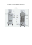
CONNECTOR FUNCTION
A DIN 8-pole connector is located on the front.
The probe or the extension cable can be directly connected to this connector. Both the probe and
the instrument have a positioning notch, while a threaded locking ring grants a tight hold.
The following connectors/sockets are located on the instrument right side
starting from the bottom upwards:
1) 20 mV/dB analogue output socket, 470 ohm output impedance.
Plug dimensions are:
∅ 2.5
11
2) Male connector for external 6÷9 Vdc power supply.
The male connector diameter is 5.5x2 mm; the central pin corresponds
to the power supply positive pole.
4
−
− +
∅2
∅ 5.5
2
1
83
+
3
ENGLISH
3) RS-232C D 9-pole male connector.
The serial link uses three lines: TX, RX and GND. A transmission protocol using software handshake (XON/XOFF) grants a baud-rate up to 19.2 kBaud.
Rx
Tx
GND
1
SERIAL OUTPUT
2
6
3
7
4
8
5
9
4) D 9-pole female connector for pre and post filter AC analogue outputs (470 ohm impedance) and
for a control output for the sound source used when measuring reverberation time (HD 9019 only).
ANALOG OUTPUT
VACPF
VACRA
GND
5
4
9
3
8
MUTE
1
2
7
MUTE: SOUND SOURCE CONTROL OUTPUT
(See technical specifications).
VACRA: PRE-FILTER AC OUTPUT (See technical specifications).
VACPF: POST-FILTER AC OUTPUT (See technical specifications).
6
SOUND
The sound is a pressure change that can be perceived by the human ear. When, for example, these variations are due to climatic changes, they are too slow to be heard, but when they are very
fast, as those resulting from drumming, they can be perceived by the human ear, and identified as
sounds.
The number of pressure oscillations per second is called sound frequency, and is measured in cycles
per second or Hertz (Hz). The human-perceptible frequency range goes from 20 Hz to 20 kHz.
The sound propagation speed in the air is 344 m/s.
1. Sound Pressure Level (SPL)
The faintest sound perceptible by the human ear is the sound corresponding to a change in the
atmospheric pressure of one part out of 5 billions, that is a change of approximately 20 millionths
Pascals (20x10–6 Pa). Despite the slightness of this pressure variation, the human ear can stand
one million times higher pressure changes.
To be able to work properly in such a wide range of values, it is much more convenient to use the
84
ENGLISH
decibel scale (dB).
By this scale, the lowest pressure change (20x10–6 Pa) corresponds to 0 dB. Every time this pressure change is increased by 10 times, 20 dB are added. In this way, for example, 2x10⁻⁴ Pa correspond to 20 dB, 2x10⁻³ Pa correspond to 40 dB and so on.
A 120 dB sound pressure level corresponds to one million times the minimum level perceptible to
humans.
2. Sound Pressure Level Stability
If the sound level changes, the instrument should follow its variations, but when they are too fast,
their instant measurement might not be achievable. In these cases, the instrument provides the
measurement of the average value. To solve this problem, the sound level meter is provided with
two response times called time weightings. They might be: FAST, used when you need to follow,
as far as possible, noise fluctuations; and SLOW, used to damp noise fluctuations down and to
detect the average value.
If the sound lasts for a very short time, that is less than one second, it is defined impulsive. For
example, typing on a typewriter and the sound of a hammer or of a gun may be classified as impulsive sounds. To estimate the level of this type of sounds, consider that the briefer the sound is, the
less sensitive the ear is in perceiving it. This is the reason why a time weighting has been defined,
whose sensitivity decreases according to the sound duration time (IMPULSE).
The risk of injuries to hearing, however, does not decrease according to the sound duration time,
thus, sound level meters generally incorporate a circuit suitable to measure the Peak level of the
acoustic signal (PEAK).
Impulsive sounds, regardless of their spectrum, are more dangerous to the human ear, because
the energy involved in the short time they last, does not allow the ear to take any defence. For this
reason the duration of these sounds is penalized by increasing the detected sound pressure level
by 3 dB to 5 dB.
A simplifying criterion to detect the presence of impulse noises, consists of detecting a difference of
over 6 dB in measurements made with SLOW and IMPULSE constants on the same noise.
3. Sound Frequency Spectrum
Pure tones in noise can cause even worst injuries to hearing than wide band noise; the phenomenon is to be found in the concentration of energy in a more restricted zone (where pure tones operate at ear level), compared with the wide band noise zone.
The search for pure tones is carried out analysing the sound pressure level for octave or fraction
octave bands. The frequency range of perceivable sounds, from 20 Hz to 20 kHz, is divided into
bands: about 10 bands for octave filters and about 30 bands for 1/3 octave filters.
A pure tone is identified when, in a 1/3 octave band, the instrument detects a sound pressure minimum level (with FAST weighting) 5 dB higher than the minimum levels detected in the adjacent
bands.
4. Equivalent continuous sound pressure level (Leq)
The danger represented by a noise also depends on exposure time. It is thus necessary to consi85
ENGLISH
der how long it lasts. The sound level shall be continuously sampled throughout a known time interval to be able to calculate the Leq representing the level of constant noise that provides the same
hearing risk as the variable noise level, during the same time.
HD 9019 and HD 9020 sound level meters are integrating sound level meters accurately measuring
the equivalent level of impulsive short sounds.
INFLUENCE OF THE ENVIRONMENT
Temperature
HD 9019 and HD 9020 sound level meters are designed to work at temperatures included between
-10°C and +50°C. However, it is advisable to avoid sudden changes, as they might cause condensate. Check also that instruments be in temperature equilibrium before executing a measurement
or a calibration: to do so, just wait an hour after the instrument has been subjected to a temperature
change.
Humidity
A relative humidity up to 90% has no effect on HD 9019, HD 9020 and on the microphone used in
HD 9019S/1 probe. In any case, protect and clean the microphone from rain and snow. By unfavourable weather conditions, it is suggested to use a windscreen and, by highly humid environments, use the microphone proper dehumidifier.
Pressure
Atmospheric pressure changes within 10% do not actually affect HD 9019 and HD 9020 measurement accuracy.
Wind
To reduce wind disturbance, use the special windscreen, made up by a polyurethane foam porous
sphere to be applied on the microphone.
It will also protect the microphone from dust, dirt and showers.
Vibrations
It is good practice to isolate instrument and microphone from vibrations.
Magnetic Fields
Electrostatic and magnetic fields actually do not affect HD 9019 and HD 9020 (just trivial effects).
86
ENGLISH
PHYSICAL PARAMETERS IN ACOUSTICS
* Frequency: Frequency is the number of oscillations per second, and it is expressed in Hertz (Hz).
* Period: Period is the time interval it takes to carry out a complete oscillation. It is expressed in
seconds (s).
* Sound propagation speed: is the distance made by the sound wavefront in the time unit,
expressed in meters/second (m/s).
* Wavelength: is the distance between two pressure maximum values. It is expressed in meters (m).
* Sound pressure: is the value of the atmospheric pressure variation caused by acoustic disturbances. It is expressed in Pascal (Pa).
* Root-mean-square value: the root-mean-square value of sound pressure (p) is the value of constant pressure corresponding to the instant compression or rarefaction value integrated in the
time interval T.
T
1)
p (rms) =
1
T
∫
p2
dt
0
where: p (rms) is the sound pressure effective value.
T is the integration time.
* RMS: means “ROOT MEAN SQUARE”, square root of the average of square values. In noise
measurements p(rms) corresponds to the square root of the arithmetic average of a sequence of
noise instant values squared.
- p(rms) is important in sound measurements as it depends on the amount of energy contained in
the sound signal.
* Crest factor: is the ratio between the signal peak level and the signal effective value, measured
with respect to the arithmetic average value.
* Decibel: a decibel (dB) is defined by:
2)
dB = 20 log10
X
Xo
where: x is the value of measured quantity.
x0 is the measurement reference value (corresponding to dB=0).
87
ENGLISH
The sound pressure level (SPL) is defined by the equation:
P2
P
= 20 log10
Po2
Po
Lp = 10 log10
3)
where: Lp = sound pressure level.
p = measured pressure level.
p0 = reference pressure value = 0.00002 = 20•10–6 Pascal.
* Equivalent continuous sound pressure level (Leq): defined as
t2
4)
Leq,T = 10
· log
10
{( ∫ ( {
1
T
Po2
P2 dt
t1
where: Leq,T is the equivalent continuous sound pressure level in a T=t2-t1 time interval.
p is the instantaneous sound pressure.
p0 is the reference pressure level corresponding to 20•10–6 Pa.
- Total Leq calculation from partial Leq measurements
If you need to know the total Leq after measuring partial Leqs, use the following formula:
n
n
Leq = 10 log ∑ i Ti 10Leq i/10 con T = ∑ i Ti
T
Example:
Suppose you have measured:
Leq1 = 80 dB in 1 h.
Leq2 = 90 dB in 2 h.
Leq3 = 50 dB in 5 h.
L2
L1
L3
t1
Leq = 10 log
t2
t3
t1 10Leq1/10 + t2 10Leq2/10 + t3 10Leq3/10
t1+t2+t3
Leq1, Leq2, Leq3 partial equivalent levels.
t1, t2, t3
equivalent levels integration times.
LeqT
total equivalent level.
88
ENGLISH
Thus T= 1 h + 2 h + 5 h = 8 h.
Getting:
Leq = 10 log ( 1 108 + 2 109 + 5 105 ) = 84.2 dB
8
8
8
* Sound Exposure Level (SEL): defined as
t2
5)
Le,T = 10
·
log10
{( ∫ ( ( · ({
P2 dt
Po2
To
t1
dove: Le,t is the sound exposure level measured in a T=t2-t1 time interval.
p0 corresponds to 20•10–6 Pa.
T0 corresponds to 1 s.
Between Leq and SEL the following relation applies:
6)
Le,T = Leq,T + 10 log10
T
dB
To
* Percentile Levels
- LN “percentile levels” are used in the statistical analysis of noise events, especially if fluctuating.
These values correspond to the noise levels exceeded during a percentage N of the total measurement time.
- For example, L10 corresponds to the noise level exceeded by 10% of the measurement time.
- For example in vehicle traffic noise measurement, the “Traffic Noise Index” is defined as:
TNI = 4 (L10- L90 ) + L90 - 30
* Dose
- The measurement of noise “Dose” is applied in the field of environmental noise monitoring with
the aim to prevent hearing injuries. A “Dose” corresponds to a percentage fraction of a maximum daily exposure to noise:
D (Q)=
100
•
Tc
∫
0
89
T
L–Lc
10
q
dt
ENGLISH
where: D(Q)
Tc
T
L
Lc
Q
q
exposure percentage corresponding to exchange rate Q.
daily exposure time (usually 8 hours).
measurement time.
sound pressure level when higher than the threshold level or – ∞.
criterion level for a daily exposure corresponding to 100% of dose.
exchange rate.
parameter dependent on the exchange rate and corresponding to:
• 10 for Q = 3 dB
• 5/log2 for Q = 5 dB
• 4/log2 for Q = 4 dB
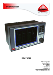
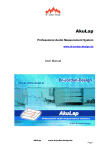
SOUND LEVEL METER BLOCK DIAGRAM
The acoustic signal is transformed by the microphone into an electrical signal and amplified by the
Pre-amplifier block integrated in the probe.
The amplified signal enters the instrument passing first through an attenuator and then through an
amplifier provided with an overload indicator (OVFL 1), and then it enters the frequency weighting
area, made up by a filter bank.
Before and after the frequency weighting, the signal is available at Vac/pre (VACRA) and Vac/Post
(VACPF) outputs, respectively.
The signal then enters the rectifying, integration and logarithmic conversion block with overload
indicator (OVFL 2), that provides the DC analogue output and the signal for the LCD display block.
90
Microphone
assembly
ENGLISH
Microphone Pre-amplifier
VAC/pre (VACRA)
Amplifier
VAC/post (VACPF)
Attenuator
Filter
Sound level meter
OVFL1
Rectifier
OVFL2
Indicator
LCD
Lin/Log
Converter
DC Log
91
ENGLISH
HD 9019/S1 MICROPHONE AND PROBE
The sensitive element of a sound level meter is the microphone. The microphone is the element
that converts the sound pressure into a proportional electrical signal.
The condenser microphone working principle is based on the microphone capacitance variation
proportional to sound signal. Microphone peculiar specifications are:
* Sensitivity: is the ratio between the effective level of open circuit output voltage and the input
acoustic pressure.
* Frequency answer: corresponds to the microphone capacitance to perceive changes, at the different frequencies, of sound signals, and it is the result of the difference between the effective level
of the open circuit output voltage at different frequencies referred to the level at 1kHz, measured
with a constant input sound pressure level.
* Directionality: is measured by the microphone sensitivity variation with the sound pressure source
direction.
HD 9019S/1 1/2" condenser microphone is suitable for free-field high-accuracy measurements
(IEC 651, type 1). Carefully manufactured and made up by best-quality components grant this
microphone long-lasting stability and accuracy.
The microphone diaphragm is protected by a removable external grid. As the diaphragm is VERY
THIN, AVOID TO TOUCH IT WITH FINGERS OR, EVEN WORST, WITH SHARPENED OR ROUGH OBJECTS, to prevent damaging it.
Protect the diaphragm from vibrations or shocks, which might damage it.
HD 9019S/1 microphone sensitivity is approx. 50 mV/Pa, which means that it produces a 50 mV
voltage by 1 Pascal sound pressure. Polarization voltage is 200 V. Maximum detectable level (by
3% distortion) is 146 dB.
Microphones with free-field response have a flat frequency response in a plane wave sound field.
Furthermore, they are designed to compensate disturbance introduced into the sound field and
caused by the microphone itself. In a free-field, the sound pressure level decreases by 6 dB doubling the distance from the source.
To carry out free-field measurements, point the free-field response microphone directly towards the
92
ENGLISH
sound source.
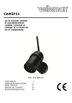
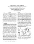
The omni-directionality of a microphone is the capacity to regularly detect (with no attenuation with
respect to its rated sensitivity) any sound pressure variation, whatever the sound source direction
is. Actually, there is a sensitivity attenuation depending on the angle of incidence due to the
microphone and instrument body. The following drawings show the typical response diagrams at
different frequencies depending on the angle of the HD 9019S/1 condenser microphone with
respect to the sound source.
1 kHz
z
kH
12,5
0db
-20db
b
0d
-10db
-20db
-10db
8k
Hz
Hz
3k
0.6
4 kHz
20 kHz
kHz
16
-10db
93
0db
-20db
0db
-20db
-10db
Hz
2k
-10
-5
0
dB
+5
➛
94
B
B
5
200 Hz
102
2
5
103
➛
2
5
Microphone capsule MK 221. Frequency response
B = microphone sensitivity
= in free field
= in pressure field
2
20 lg
104
2
Hz
ENGLISH
ENGLISH
INSTRUMENT WORKING
1. Power-on and Power-off
Press ON/OFF key to power the instrument on or off.
The AUTO POWER-OFF device switches the instrument automatically off if no key has been pressed for 8 minutes (except ON/OFF and RESET keys).
If upon power-on you keep the HOLD key pressed (for the whole power-on routine), the auto
power-on function will be disabled and the instrument will turn off only pressing the ON/OFF key
again. While working with auto power-off disabled, the battery symbol flashes to remind the user
that he has to press ON/OFF to turn the instrument off.
Upon power-on, the instrument executes an internal check; the reading stabilization time is approx.
30 seconds.
If, upon power-on, and during the whole power-on routine, CAL and SERIAL OUTPUT keys
are hold pressed, the instrument, after switching on, executes an initialisation of configuration and calibration parameters (general RESET), deleting all memories and then turns off.
When switching it on again, the instrument will execute a memory check, lasting about 3
minutes and displaying the number of inspected blocks.
When the check is over, the instrument will switch on regularly, and, if a memory malfunction was
detected, the FULL symbol will be displayed. After a general RESET, a calibration of the instrument
must be carried out, before making any measurement.
2. Frequency Weightings
The measurement of the sound pressure level, as perceived by a person, aimed to measure its noise or the risk of hearing injuries, has involved world-wide the introduction of A, B, C and D frequency weighting curves.
The reason of these curves is due to the non-linear behaviour of the sound/noise sensation by the
human ear.
The “A” filter is used to measure the hearing disturbance/injury or risk, and “D” filter to measure noise caused by the aircraft traffic.
When more detailed information about a complex sound signal are requested, the perceivable frequency range can be divided into different sections having an octave, or, even better, 1/3 octave
amplitude.
When the division is by octave bands, the upper frequency of each octave is twice that of the previous one; an octave band is thus included between two frequencies, where the higher boundary is
twice the lower one.
When the division is by 1/3 octave bands, each band is included between two frequencies, where
the higher boundary is 1.26 (or exactly 21/3) times the lower one. A filter bank executing this sound
frequency division rejects all signals having frequencies out of the boundaries of the selected filter.
For example, a 1/3 octave filter, with 1 kHz centre frequency, allows to measure sounds included
between 891 Hz and 1123 Hz, attenuating all the others.
This sound measurement process providing different frequency bands is named “frequency analysis” (see Progr. 2), whose results can be collected and represented in a histogram.
Sometimes, some kinds of noises are distinguished by a particular sound power frequency spec95
ENGLISH
trum. A “white noise” means that the sound power is constant over the perceivable frequency range
or, at least, over the range of frequencies characterizing the noise itself. A “pink noise” means that
the acoustic power is inversely proportional to frequency in a known range.
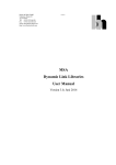
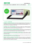
HD 9019 and HD 9020 execute measurements with A, B, C, D (HD 9019 only) weighting filters, all
type 1 according to IEC 651 standard; with LIN (linear 16 Hz, 16 kHz) and with 1/3 octave bands
from 16 Hz to 20 kHz, type 2 according to IEC 1260 standard.
The diagram below indicates the typical frequency response of A, B, C and D filters.
20
10
dB
D
0
A
C
-10
C, B
D
-20
B
-30
-40
A
-50
20
50
100
200
500
1000 2000
5000 10000 20000
One third of
an octave filter
One octave filter
3
f2= 2 f1=1.26f1
f2=2f1
B=0.7f0
B
1/
1
B=0.25f0
B
1/
3
ottava
ottava
Hz
f1
f0=1000
Hz
Hz
f0=1000
f2
f1
96
f2
ENGLISH
Pressing POND, the following filters are selected in succession:
(HD 9019 only)
A
B
C
LIN
D
OCTAVE
Pressing OCT, the display shows the value of the filter centre frequency expressed in kHz. Use
and keys to select the desired 1/3 octave filter.
t
s
One-third octave band nominal frequencies are 32:
Pos.
Low
Limit
Nominal
frequency (Hz)
High
Limit
Pos.
Low
Limit
Nominal
frequency (Hz)
High
Limit
1
2
3
4
5
6
7
8
9
10
11
12
13
14
15
16
14.1
18
22.4
28
35.5
45
56
71
90
112
140
180
224
280
355
450
16
20
25
31.5
40
50
63
80
100
125
160
200
250
315
400
500
18
22.4
28
35.5
45
56
71
90
112
140
180
224
280
355
450
560
17
18
19
20
21
22
23
24
25
26
27
28
29
30
31
32
560
710
900
1.120
1.400
1.800
2.240
2.800
3.550
4.500
5.600
7.100
9.000
11.200
14.000
18.000
630
800
1.000
1.250
1.600
2.000
2.500
3.150
4.000
5.000
6.300
8.000
10.000
12.500
16.000
20.000
710
900
1.120
1.400
1.800
2.240
2.800
3.550
4.500
5.600
7.100
9.000
11.200
14.000
18.000
22.400
The use of OCTAVE weighting increases by approximately 35% the instrument power consumption, thus, when 1/3 octave filters are not necessary, it is much more convenient to choose
another weighting. This allows to better exploit battery life.
3. Amplifier Gain
The instrument input amplifier has a 1÷1,000 programmable gain (from 0 dB to 60 dB).
The selection of the most suitable gain is carried out manually by increments of 20 dB.
Pressing RNG, the display shows the relevant symbol and the value expressed in decibel of current
amplification. Use and keys to select the most suitable amplification for the measurement range; a red LED indicates the selected value.
s
t
0 dB
40 dB
20 dB
97
60 dB
ENGLISH
A
dB
GAIN
60
40
20
0
db
If during the reading with a given amplification, the input signal level goes too high, OVFL will
appear on display to indicate that a signal overload has occurred in the amplifier. Press RESET to
delete the overload indication. If the symbol lights up frequently, a lower amplifier gain should be
selected. Similarly, when measured level goes too low, the instrument will display the measured
value and the UF (underflow) symbol alternatively. In this case, the amplification should be increased.
To every amplifier gain corresponds a measurement input level range, within which the instrument
maintains its accuracy specifications. HD 9019S/1 measurement ranges are:
Range
0 dB
20 dB
40 dB
60 dB
sound pressure level
measurement range
140÷80 dB
120÷60 dB
100÷40 dB
80÷20 dB
The boundaries of the Peak level measurement ranges are 3 dB higher than the listed ones.
The minimum SPL measurable in the most sensitive range (with a 60 dB gain), is affected
and limited by the background noise of the instrument, depending on the selected frequency weighting (see the “Technical Specification” paragraph).
4. Measurement Channels
HD 9019 and HD 9020 can measure simultaneously several quantities combined with the sound
pressure level. During the Leq integration time, the instrument can detect simultaneously the weighted sound pressure level (SPL) by selecting between FAST, SLOW or IMPULSE and the relevant maximum and minimum values. Actually, if you press RESET, SPL maximum and minimum
values are cleared, while Leq, SEL and Dose values are initialised (HD 9019 only).
If you press CHN repeatedly, one of the following measurement channels will be displayed:
HD 9019
SPL
Dose
HD 9020
Leq
Dose 8h
SPL
SEL
Leq
SEL
98
ENGLISH
4.1 Sound Pressure Level (SPL)
The SPL can have a SLOW, FAST, IMPULSE or PEAK weighting (selectable using the SPL CONST key). The symbol (S, F, I or P) corresponding to the selected weighting time lights up on the
right side of display.
F
S
P
I
The instrument automatically updates SPL minimum and maximum values. When the SPL channel
is displayed, if you press the MAX/MIN key repeatedly, maximum (MAX), minimum (MIN) and current values will be displayed.
Press RESET to clear minimum and maximum values.
Leq, SEL, Dose (HD 9019 only) and SPL minimum and maximum values are calculated simultaneously with the current value of the sound pressure level. Only during the measurement of the
Peak level (PEAK) no other measurement is available.
4.2 Equivalent Continuous Sound Pressure Level (Leq) and Sound Exposure Level (SEL)
The Leq, or equivalent continuous sound pressure level, is calculated integrating the sound level
with the time.
Leq and SEL are calculated starting when you press RESET, and are integrated for a time corresponding to the programmed value. To set this value, press LEQ TIME and use and keys:
s t
0.125s
0.5s
12h
1s
8h
5s
10s
4h
1h
30s
1m
30m
5m
15m
When you press RESET, Leq and SEL calculation starts, and their current values can be displayed
pressing CHN until the respective symbol (LEQ or SEL) lights up. The update of displayed value is
over when programmed integration time has been reached.
Current integration time can be read pressing (h.m) for hours and minutes. Numbers on the left
side of the point indicate the elapsed hours, while the other two numbers correspond to the elapsed
minutes. Press (s) key to read seconds.
If you press HOLD, Leq update can be temporarily interrupted; for example, to exclude unwanted
noise events from integration. Pressing HOLD again, the integration resumes.
t
s
4.3 Dose (HD 9019 only)
As for the Leq calculation, 8 h DOSE (that is the 8-hour estimated dose for an exposure at current
levels) and DOSE are calculated starting from the moment when RESET is pressed, and integrated
for a time corresponding to the programmed LEQ TIME value.
THR, EXCH and CRIT parameters are used for the calculation, respectively: Threshold Level (Leq
99
ENGLISH
minimum value considered), Exchange Rate (selectable among 3 dB, 4 dB and 5 dB) and Criterion
Level (reference level for a 100% daily exposure).
Sound pressure levels lower than the Threshold Level are not considered in the dose calculation.
An equivalent level corresponding to the Criterion Level, throughout an 8-hour integration time, provides a 100% dose.
An equivalent level equal to the Criterion Level, decreased by the Exchange Rate, provides a 50%
dose over an 8-hour integration time.
An equivalent level equal to the Criterion Level, increased by the Exchange Rate, provides a 200%
dose over an 8-hour integration time.
As for Leq, dose update can be temporarily interrupted pressing HOLD, and pressing HOLD
another time the calculation resumes.
Dose calculation stops when the programmed integration time is reached. Press RESET to execute
a new measurement.
5. Direct Printing
Pressing SERIAL OUT, the instrument sends, through the RS-232C serial interface, the displayed
value directly to a printer or to a personal computer. Pressing SERIAL OUT while any of the sound
level meter parameter is displayed (see Parameters), the instrument sends the current values of all
parameters. Pressing SERIAL OUT while setting the amplifier gain (RNG), the instrument sends
the following information:
• sound level meter model and relative revision number;
• date and time;
• input amplifier current gain;
• equipped memory size.
6. Storage
HD 9019 and HD 9020are provided with a 512 kByte memory bank for measurement storage.
All measured and calculated data (in a known instant) can be written to memory simply pressing
the STORE key when the PROG symbol is not light up on display (“Single data record”).
The memory is organized in sequences and every data record is preceded by a header including
time and date in addition to all other parameters that might be useful to identify the measurement
conditions.
1, 2 and 4 (HD 9019 only) programs automatically store, by preset time intervals, Leq measured
values, while program 6 allows stored data downloading directly to a printer or to a personal computer.
Memory capacity grants:
• 5000 “Single data record” (STORE);
• 9 hours of “Leq history and statistics” (PROG 1) at a 1/8 second integration time;
• 5000 “Frequency spectrum” (PROG 2) frequency analysis;
• 50 “Reverberation time calculation” (PROG 4) (HD 9019 only).
100
ENGLISH
7. Programs
HD 9019 and HD 9020 sound level meters are provided with automatic storage of measured Leq
values.
Pressing PROG repeatedly, you can select one of the following parameters:
Prog 1: Leq history and statistics.
Prog 2: Frequency spectrum.
Prog 4: Reverberation time calculation (HD 9019 only).
Prog 6: Memory dump.
P1
P2
P6
P4
The selected program is activated or stopped by pressing START/STOP. When the program is running, the PROG symbol flashes.
If, to start the program, Serial Out is pressed instead of Start, measurements are sent directly to the serial output and not to the instrument memory.
101
ENGLISH
Program 1 stores a Leq sequence. Leq first is integrated for the programmed time (LEQ TIME),
then it is compared with the programmed threshold (THR MIN) and, if the value exceeds the threshold level, the Leq is stored.
The integrations, of duration corresponding to the programmed value (LEQ TIME), follow one
another cyclically and without interruptions until the STOP key is pressed.
When you press STOP, Leq history storage stops and the instrument processes the statistical
analysis of the measurements, calculating L10, L50 and L90 percentile levels. L10 is the first value
displayed. Pressing STOP again, L50 will be displayed, while L90 appears if STOP is pressed for
the third time.
Press STOP once more to quit the program.
The statistical analysis can be stored alone by pressing before and contemporaneously with
START.
If you press Serial Out instead of START, the program header is first sent to the serial link and, at
the end of the measurement sequence, pressing STOP L10, L50 and L90 percentile levels are
printed. Press STOP three more times to exit the program.
s
102
ENGLISH
103
ENGLISH
Program 2 stores one 5-second Leq for each 1/3 octave band in automatic scanning from 16 Hz to
20 kHz.
The program automatically stops when scanning is over. Press STOP if you need to interrupt it
before.
If you press SERIAL OUT instead of START, the program header and the measured values will be
sent directly to the serial link.
104
ENGLISH
Program 4 (HD 9019 only) is used to calculate the reverberation time both with the technique of
sound source interruption and with the integrated impulsive response technique.
In the first case, it is necessary to control the source through the HD 9019 sound level meter MUTE
output (see Connectors): the source shall be on with MUTE output open, and off with MUTE output
closed.
ANALOG OUTPUT
VACPF
VACRA
GND
5
4
9
3
8
MUTE
1
2
7
6
MUTE
MUTE
Source ON
Source OFF
In case of measurement with interruption of the sound source, the Event Threshold parameter
(THR MIN) shall be set at a value lower than the source-generated noise, which shall exceed the
background noise by 40 dB, at least.
Pressing START, the HD 9019 sound level meter will suddenly interrupt the sound source by switching the MUTE output and the Leq values (integrated for 1.25 ms) are stored 800 times/second.
Sampling will stop as soon as the Leq drops 35 dB below the starting level, or as soon as 5 s have
elapsed.
105
ENGLISH
T10, T20 and T30 values will now be stored and calculated evaluating the reverberation time
(60 dB drop) from the difference between the instant when the Leq went 5 dB below the starting
level and 15 dB, 25 dB and 35 dB below such a level, respectively.
In case of measurement through the integrated impulsive response, set Event Threshold (THR
MIN) at a value higher than the background noise, as closest as possible to the maximum level reached by the impulsive source signal, without exceeding it.
After pressing START, the instrument waits for the measured Leq to exceed the Event Threshold
(THR MIN). When the threshold is exceeded, the Leq values (integrated for 1.25 ms) are stored
800 times/second.
Sampling will interrupt as soon as the Leq drops 35 dB below the maximum reached level, or when
5 s have elapsed since threshold was exceeded.
T10, T20 and T30 values will now be stored, calculated evaluating the reverberation time from the
differences between the instant the Leq went 5 dB below the starting level and 15 dB, 25 dB and
35 dB below such a level, respectively.
If you press STOP, or if the reverberation time calculation is over, or if more than 5 s have elapsed
since the beginning, T10 value will be displayed. Press STOP again to display T20, while T30 will
appear pressing STOP for the third time. Press STOP once more to quit the program.
Keep pressed (contemporaneously with START) to store T10, T20 and T30 values only.
s
To measure reverberation time, position the sound source and the sound level meter far from walls
and reflecting surfaces, as well as far one from the other. Measurements shall be executed using
the 1/3 octave filters and they have to be repeated for several centre frequencies.
Program 6 allows downloading HD 9019 and HD 9020 stored data, directly to a printer or to a personal computer using the RS-232C link.
Pressing START the display shows P6 and all stored measurements are downloaded through the
RS-232C serial link (memory dump); the program will automatically stop. If you need to interrupt it
before, press STOP. Press and hold pressed the key while pressing START to download only
stored data headers.
No memory reset is automatically carried out after executing program 6.
While PROG 6 is displayed, press RESET to clear the memory contents.
If memory has been accidentally zeroed, you can restore data keeping the key pressed contemporaneously with START.
s
t
106
ENGLISH
8. Calendar
The calendar clock can be programmed using DATE,
tedly, you can select:
1
year
s
s and t keys. If you press DATE repea-
2
month
5
minutes
t
3
day
4
hours
Using and keys, displayed values can be increased or decreased, until the correct date and
time settings are achieved.
The calendar updates also while the instrument is off and has to be readjusted or checked every
time you replace batteries.
9. Parameters
Press PAR repeatedly to select the following parameters:
HD 9019
THR
EXCH
EVEN THR
CRIT
HD 9020
THR MAX
THR
BAUD RATE
BAUD RATE
EVEN THR
- “Threshold Level”, “Exchange Rate” and “Criterion Level” (respectively displayed as THR, EXCH
and CRIT) are used in the DOSE calculation (HD 9019 only).
• “Threshold Level” is the SPL threshold for DOSE calculation. The value can be programmed in
the 0 dB ÷ 90 dB range with increments of 5 dB.
• “Exchange Rate” is the SPL decrement that doubles the exposure time for the same dose at a
given “Criterion Level”. This value can be selected among 3 dB, 4 dB and 5 dB.
3dB
4dB
5dB
• The “Criterion Level” is the constant SPL providing a 100% dose for an exposure of 8 hours. The
value can be programmed in the 0 dB ÷ 150 dB range, with increments of 1 dB.
- Threshold MAX (THR MAX) is the Leq threshold for the OVFL overload symbol activation. The
value can be programmed in the 0 dB ÷ 150 dB range, with increments of 1 dB.
- Baud Rate establishes the RS-232C serial link baud-rate, selectable among:
600
19200
1200
9600
4800
2400
- Event Threshold (THR MIN) is the threshold of the noise event used in program 1 and 4; the
instrument waits for the Leq to exceed this value to make its calculations and possible storages:
WHEN Leq IS BELOW THIS VALUE, NO STORAGE IS CARRIED OUT. The value can be programmed in the 0 dB ÷ 150 dB range with increments by 1 dB.
107
ENGLISH
10. Sound Level Meter Calibration
The instrument, according to the standards in force, has to be calibrated to provide correct measurements.
Instruments that provide an accurate sound pressure level directly on the instrument microphone
are generally used for the calibration. The most common are pistonphones and electronic calibrators.
HD 9019 and HD 9020 have to be preferably calibrated at 1kHz reference frequency and at 94 dB
reference sound pressure level. A calibration at 250 Hz is possible too.
The HD 9101 calibrator provides a 94 dB sound pressure level at 1000 Hz frequency.
The HD 9101 calibrator specifications correspond to type 1, according to IEC 942 standard
(IEC 60942/1997).
Calibration is generally checked before and after a measurement set. The measurements will be
considered valid if the difference between the two verifications is lower than 0.5 dB.
To calibrate the instrument, insert the microphone in the calibrator seat.
BOTH THE CALIBRATOR AND THE INSTRUMENT SHALL BE OFF. Inserting the microphone
involves a slight stress caused by the gasket of the calibration chamber. It is suggested to position
the instrument and the calibrator on the same plane, at the same level, aligning the axis.
108
ENGLISH
Press ON/OFF on the calibrator and select 94 dB sound pressure level (at 1000 Hz frequency).
Press ON/OFF on the sound level meter, wait until calibrator and sound level meter are stable
(approx. 60 seconds).
Here are calibration instructions:
• Select the input amplifier gain (RNG), corresponding to 20 dB.
• Press CAL keeping SERIAL OUT pressed: PROG 5 will be displayed.
• Press o to adjust the displayed value and select 94 dB correct value (no correction has to be
applied to calibrate the MK221 microphone for free-field measurements).
• Be sure reading is stable.
• Press CAL: the instrument will now automatically execute the calibration procedure in 10 steps (9
steps for HD 9020).
• A long “beep” at the end indicates that calibration has been carried out successfully.
• If during this procedure the instrument quits the calibration function without emitting any
sound, check whether the calibrator generates a correct signal and whether the amplifier
gain (RNG) is properly set.
• If the procedure interrupts, repeat the calibration operation starting from the beginning.
s t
You can calibrate the instrument at sound pressure levels higher than 94 dB. For levels higher than
114 dB, you shall use a 0 dB input amplifier gain.
Calibration is a very important function and it has to be carried out very carefully and meticulously.
109
ENGLISH
After calibrating, press ON/OFF to switch off both the calibrator and the sound level meter and take
the microphone out the calibrator seat. The sound level meter is now calibrated.
Often you might simply have to check that the sound level meter properly reads the level generated
by the calibrator. In this case you just have to:
• insert the microphone in the calibrator seat;
• turn the calibrator and the sound level meter on;
• set 94 dB on the calibrator;
• set RNG at 20 dB on the sound level meter;
• set the sound level meter at SPL channel constant SLOW and weighting “A”.
Now, when reading is steady (wait approx. 1 minute), check that the value read by the sound level
meter corresponds to 94 dB with a 0.3/0.5 dB maximum error. If the difference exceeds these
limits, the sound level meter needs to be calibrated according to the procedure described above.
11. Windscreen
Noise measurements in open spaces might be affected by the wind. To attenuate the wind pressure on the diaphragm, the microphone can be protected by a spherical cover made of open-pored
polyurethane foam (HD SAV).
12. Measurement on Tripod
When measuring noise, pay attention that the operator’s body, the instrument case or its support
could spoil the measurement.
Keep the instrument as far as possible from the operator’s body, and eventually fix it on a tripod to
minimize the impact on noise measurements.
110
ENGLISH
13. Low Battery Signal
HD 9019 and HD 9020 instruments are powered by 4 x 1.5 V R6-AA-UM3 alkaline batteries. If battery voltage drops below 1 V, the battery symbol will be displayed. This signal indicates to the operator that batteries are low and that they will provide only one more hour operating.
It is suggested to use best quality batteries. Do not leave exhausted batteries around, but through
them into proper containers.
If the instrument is not used for a long time, take batteries off their seat to avoid damages due to
corrosive liquid leakage.
NOTE: the flashing battery symbol does not indicate that batteries are low, but just that the
auto power-off function is disabled.
14. Remote Control
The instrument is provided with a bi-directional RS-232C serial interface.
Rx
Tx
GND
SERIAL OUTPUT
1
2
6
111
3
7
4
8
5
9
ENGLISH
600, 1200, 2400, 4800,
9600, 19200 BAUD
8 BIT DATA LENGTH
1 START BIT
1 STOP BIT
NO PARITY
XON/XOFF
13
25
12
24
11
23
10
22
9
21
8
20
7
19
6
18
5
17
4
16
3
15
2
14
1
1
6
2
7
3
8
4
9
5
HD 9019
COMPUTER
Except upon power-on and power-off, the instrument can be controlled via the RS-232C. Command
ASCII codes are listed in the following table.
ASCII Codes
character command
0
10
11
12
2
3
40
41
42
43
44
45
50
51
52
53
600
601
.
.
.
hold
current value
max value
min value
serial out
reset
pond=LIN
pond=A
pond=B
pond=C
pond=D
(HD 9019 only)
pond=OCTAVE
const=FAST
const=SLOW
const=IMPULSE
const=PEAK
octave=16 Hz
octave=20 Hz
character command
630
631
70
71
72
73
800
801
.
.
.
812
813
90
91
92
93
94
L
M
octave=16 kHz
octave=20 kHz
range=0 dB
range=20 dB
range=40 dB
range=60 dB
inttm=0.125 s
inttm=0.5 s
character command
C0
C1
C2
C4
C6
D<val>
E<val>
F<val>
inttm=8 h
inttm=12 h
chn=SPL
chn=Leq
chn=SEL
chn=Dose 8 h
(HD 9019 only)
chn=Dose
(HD 9019 only)
start
start+∆
112
G<val>
H0
H1
H2
H3
H4
H5
J<val>
K
AA
prog=0
prog=1
prog=2
prog=4 (HD 9019 only)
prog=6
val dB=thr
val 2 digits
(HD 9019 only)
val dB=exch val 1 digit
(HD 9019 only)
val dB=crit
val 3 digits
(HD 9019 only)
thrmax=val
val 3 digits
baudrt=600
baudrt=1.2 k
baudrt=2.4 k
baudrt=4.8 k
baudrt=9.6 k
baudrt=19.2 k
val dB=evnthr val 3 digits
instrument general reset
instrument identification
ENGLISH
KEYBOARD FUNCTION
KEY
ON/OFF
LIT-UP SYMBOLS IN
ADDITION TO DIGITS
PROG
FUNCTION
DESCRIPTION
Key to be used to power the
instrument on and off.
FULL HLD RNG OVFL
I P
S F
dB %
kHz
AB
CD
LIN EXT
OCTAVE
TIME LEQ SEL DOSE THR EXCH CRIT MAX MIN
HOLD
Key to be used to interrupt display
update or to stop the Leq integration. If it is pressed contemporaneously with ON/OFF and it is
hold pressed for the whole
power-on routine, it excludes
the AUTO POWER-OFF function. The battery symbol flashes.
HLD
A
dB
F
+
MAX/MIN
A
dB
Key to be used to display the
sound pressure level (SPL) MAXIMUM and MINIMUM values.
F
I
F
MAX
MINdB
RESET
A
P
dB
113
- It zeroes the MAXIMUM and
MINIMUM stored values.
- It zeroes both Leq and overflow
(OVFL 1 and 2 symbols).
- It zeroes SEL and DOSE.
- It zeroes the peak value.
- It zeroes the memory contents if
PROG 6 symbols are displayed
(memory dump).
ENGLISH
KEY
SERIAL OUT
LIT-UP SYMBOLS IN
ADDITION TO DIGITS
PROG
A
dB
CAL
PROG
+
+
FUNCTION
DESCRIPTION
A
LIN
dB
+
114
F
Key to be used to enable the
serial transmission of displayed
channel.
Every time this key is pressed the
displayed value is sent to the
serial link.
- If 1, 2 or 4 programs are selected (PROG 1, 2 or 4 symbols lit),
the program starts and enables
serial data transmission, instead
of data storage. Press STOP to
interrupt the program (some programs request STOP to be pressed several times and not just
once). PROG and the battery
symbols flash.
- If you are programming the
amplifier gain (RNG symbol lit),
it prints a header containing date
and time with the main information concerning the type of probe, the internal memory size and
the current amplifier gain.
- While programming the parameters, all current values are printed.
CAL. Key to be pressed while
keeping SERIAL OUT pressed to
start the calibration procedure
(PROG 5 symbol lights-up). Press
CAL to confirm the reference
value and start the 10-step automatic procedure (9 steps for
HD 9020).
ENGLISH
KEY
LIT-UP SYMBOLS IN
ADDITION TO DIGITS
FUNCTION
DESCRIPTION
POND
B
D
LIN
A
dB
C
F
OCTAVE
This key, repeatedly pressed,
selects frequency weightings: A,
B, C, D (HD 9019 only), OCTAVE, LIN.
SPL CONST
A
dB
F
S
dB
I
dB
OCTAVE
P
dB
This key, repeatedly pressed,
selects the time weightings for
SPL measurement:
F = fast
S = slow
I = impulse
P = peak
This key activates the selection of
the 1/3 octave band filter centre
frequency. The centre frequency
can be adjusted through and
keys.
+
s
OCTAVE
kHz
115
t
ENGLISH
KEY
LIT-UP SYMBOLS IN
ADDITION TO DIGITS
RNG
+
GAIN
60
40
20
0
db
LEQ TIME
FUNCTION
DESCRIPTION
This key activates the selection of
the input amplifier gain and, thus,
the measurement range.
- Amplification is adjusted through
and keys.
A red LED indicates the current
amplifier value.
s t
This key activates the selection of
the Leq integration time in
seconds, minutes and hours.
- The value can be adjusted
through and keys.
- When you press this key, the
Leq is zeroed and a new measurement is started.
+
s t
TIME LEQ
DATE
+
TIME
1
year
2
month
5
minutes
TIME
TIME
TIME
3
day
4
hours
TIME
This key allows updating the
calendar.
- If repeatedly pressed, year (1),
month (2), day (3), hour (4) and
minutes (5) values can be modified by means of and keys.
s t
116
ENGLISH
KEY
LIT-UP SYMBOLS IN
ADDITION TO DIGITS
FUNCTION
DESCRIPTION
CHN
This key activates the selection of
the measurement channel.
A
F
I
P
dB
I P
dB
LEQ
%
SEL
%
DOSE THR
DOSE
SPL
Dose
Leq
Dose P
SEL
PAR
- If repeatedly pressed, it activates
the following channels: SPL, Leq,
SEL, DOSE 8-hours (HD 9019
only), DOSE (HD 9019 only).
This key allows updating the
values of some instrument parameter.
dB
dB
THR
dB
EXCH
dB
CRIT
SEL
THR
MAX
kHz
dB
SEL
THR EXCH
THR
THR MIN
EXCH
BAUD RATE
CRIT
THR MAX
117
MIN
- If repeatedly pressed, it activates the following parameters:
- Threshold (HD 9019 only),
Exchange Rate (HD 9019 only),
Criterion Level (HD 9019 only),
Threshold Max, Baud Rate and
Event Threshold.
ENGLISH
KEY
LIT-UP SYMBOLS IN
ADDITION TO DIGITS
PROG
FUNCTION
DESCRIPTION
This key activates programs 1, 2,
4 (HD 9019 only) and 6 in
sequence.
PROG
PROG
PROG
PROG
These keys allow changing the
displayed value in many constant
or parameter edit functions.
- If is hold pressed, it displays
Leq integration time HOURS
and MINUTES.
- If is hold pressed, it displays
Leq integration time SECONDS.
s
t
START/STOP/
STORE
This key starts and stops programs 1, 2, 4 (HD 9019 only),
and 6; when pressed with no program selected (PROG symbol off)
all measurement channels are
stored in a single data record
(PROG 0 single data record).
118
ENGLISH
DISPLAY SYMBOL FUNCTION
LIT-UP SYMBOLS IN
ADDITION TO DIGITS
FUNCTION
DESCRIPTION
PROG
A
LIN EXT
dB
F
PROG
A
I
dB
F
PROG
A
dB
F
PROG
A
dB
F
PROG 1
This symbol appears when selecting program number 1:
“Leq Monitoring and Statistical Analysis”.
PROG 2
This symbol appears when selecting program number 2:
“1/3 Octave Band Automatic Scanning”.
PROG 4
This symbol appears when selecting program number 4:
“Reverberation Time Measurement” (HD 9019 only).
PROG 5
This symbol appears when starting the instrument automatic calibration program.
119
ENGLISH
LIT-UP SYMBOLS IN
ADDITION TO DIGITS
FUNCTION
DESCRIPTION
PROG
A
dB
F
PROG 6
This symbol appears when selecting program number 6 for
memory dump via RS-232C.
FULL
This symbol appears when memory is full.
FULL
A
dB
F
HLD
dB
F
RNG
This symbol is lit while changing the input amplifier gain
and selecting the measurement range.
RNG
I
LIN EXT
HLD
This symbol appears when the HOLD key is pressed
(display update and Leq integration consequently suspended).
dB
OVFL
A
dB
F
OVFL 1
This symbol lights up when the instrument detects an overload on the input amplifier.
The symbol remains lit until measurement conditions are
not changed, such as measurement range, frequency weighting, etc., or until RESET is pressed starting a new measurement.
120
ENGLISH
LIT-UP SYMBOLS IN
ADDITION TO DIGITS
FUNCTION
DESCRIPTION
OVFL
A
dB
I
dB
A
dB
P
F
F
OVFL 2
This symbol lights up when the instrument detects a converter overload, or when THR MAX programmed threshold
has been exceeded.
It is cleared pressing RESET.
K
H
This symbol flashes when the instrument auto power-off is
disabled. If the symbol is always lit, it means that batteries
are exhausted.
F
A
The symbols lights-up according to the selected frequency
weighting.
B
B
dB
F
C
C
dB
F
121
ENGLISH
LIT-UP SYMBOLS IN
ADDITION TO DIGITS
FUNCTION
DESCRIPTION
D
Not available on HD 9020.
D
dB
F
OCTAVE
OCTAVE
dB
F
LIN
LIN
dB
A
I
dB
F
F
F
These symbols light up accordingly to the time weighting
selected for SPL measurement:
FAST,
S
SLOW,
A
S
dB
122
ENGLISH
LIT-UP SYMBOLS IN
ADDITION TO DIGITS
FUNCTION
DESCRIPTION
I
IMPULSE,
A
I
dB
P
Peak.
A
P
dB
A
I P
F
dB
This symbol indicates that the displayed value is in decibels.
dB
A
A
F
%
D
F
%
This symbol indicates that the displayed value is in % (not
available on HD 9020).
kHz
This symbol indicates that the displayed value is in kHz
(thousands of Hertz).
kHz
123
ENGLISH
LIT-UP SYMBOLS IN
ADDITION TO DIGITS
FUNCTION
DESCRIPTION
Leq TIME
This symbol indicates that the displayed value is expressed
either in seconds, minutes or hours.
0.125s
TIME LEQ
0.5s
12h
1s
8h
5s
4h
10s
1h
30s
1m
30m
5m
15m
TIME 1
This symbol appears when updating the calendar to indicate that the displayed value is the year.
TIME
TIME 2
This symbol appears while updating the calendar to indicate that the displayed value is the month.
TIME
TIME 3
This symbol appears while updating the calendar to indicate that the displayed value is the day.
TIME
TIME 4
This symbol appears while updating the calendar to indicate that the displayed value is the hour.
TIME
124
ENGLISH
LIT-UP SYMBOLS IN
ADDITION TO DIGITS
FUNCTION
DESCRIPTION
TIME 5
This symbol appears while updating the calendar to indicate that the displayed value corresponds to minutes.
TIME
LEQ
This symbol appears when Leq channel is displayed.
A
dB
LEQ
SEL
This symbol appears when SEL channel is displayed.
A
dB
SEL
A
P
DOSE P
This symbol appears when the 8-hour Dose is displayed
(not available on HD 9020).
%
DOSE
DOSE
This symbol appears when the current Dose is displayed
(not available on HD 9020).
A
%
DOSE
125
ENGLISH
LIT-UP SYMBOLS IN
ADDITION TO DIGITS
FUNCTION
DESCRIPTION
dB
THR
This symbol appears when the Threshold Level parameter is being modified to calculate the Dose (not available
on HD 9020).
dB
EXCH
This symbols appears when the Exchange Rate parameter is being modified to calculate the Dose (not available
on HD 9020).
dB
CRIT
This symbol appears when the Criterion Level parameter
is being modified to calculate the Dose (not available on
HD 9020).
THR
EXCH
CRIT
THR MAX
This symbol appears when the THRESHOLD MAX parameter is being modified.
dB
THR
MAX
THR MIN
This symbol appears when changing the Event
Threshold.
dB
THR
MIN
126
ENGLISH
LIT-UP SYMBOLS IN
ADDITION TO DIGITS
A
dB
FUNCTION
DESCRIPTION
F
MAX
This symbol appears when the SPL maximum value is
displayed.
MAX
A
dB
F
MIN
This symbol appears when the SPL minimum value is
displayed.
MIN
A
dB
GAIN
60
40
20
0
db
The red LED on indicates the dB value of the amplifier gain
set through RNG and and keys.
s t
127
ENGLISH
HOW TO CONNECT A DELTA OHM SOUND LEVEL METER TO A PC WITH
WINDOWS OPERATING SYSTEM
Hardware connection:
1) The measurement instrument has to be off.
2) - Use Delta Ohm RS-232C cable, to connect the port of the instrument to the serial port available on the PC (COM1/COM2).
- Note: the CP RS-232C cable ends with a female 25-pin connector; should the PC not be
equipped with a compatible connector, use standard adapter usually on sale to connect them.
3) Turn the switch on the CP RS-232C wire to COMPUTER.
Software Connection with WINDOWS 3.1:
A) Start WINDOWS
B) Select the ACCESSORIES window (Double-click)
C) Select TERMINAL and start the communication program (Double-click)
128
ENGLISH
D) - Follow these instructions to change the terminal dialogue settings, and make them compatible
with the instrument settings (if you did not already save a terminal setting file):
select SETTINGS on the terminal window (1 click)
select COMMUNICATIONS in the pop-up menu (1 click)
- the COMMUNICATIONS window appears on screen to set the dialogue modes; set:
- BAUD RATE: 19200 and shall be the same set on the instrument (1 click)
DATA BITS: 8 (1 click)
STOP BITS: 1 (1 click)
PARITY: none (1 click)
FLOW CONTROL: Xon/Xoff (1 click)
CONNECTOR: COM1 or COM2 according to the port used for the connection (1 click)
PARITY CONTROL and CARRIER DETECT shall remain marked
OK to confirm (1 click)
129
ENGLISH
E) - To save this setting on terminal:
select FILE on the terminal window (1 click)
- select SAVE AS in the pop-up menu and the SAVE FILE AS window will appear (1 click)
enter the name of the terminal setting file in the box (up to 8 characters)
OK to confirm and save the configuration (1 click)
130
ENGLISH
F) To receive and store instrument data:
select TRANSFER on the terminal window (1 click)
select RECEIVE TEXT FILE in the pop-up menu and the window appears (1 click)
enter the name of the file where data have to be stored (up to 8 characters)
OK to confirm and start storing (1 click)
Now the terminal is ready to receive data from the instrument. All data the instrument will send will
be stored on the a.m. file.
G) Turn the sound level meter on.
When the power-on routine is over, start downloading data stored on the internal memory using the
P6 program (see the user’s manual), and press the START/STOP key.
131
ENGLISH
H) Ending storage of data received by the instrument:
select TRANSFER on the terminal window (1 click)
select STOP in the pop-up menu to stop storing (1 click)
The software goes back to the terminal window.
I) How to quit TERMINAL:
select FILE on the terminal window (1 click)
select QUIT in the pop-up menu (1 click)
The text file, containing data received from the measurement instrument connected to the PC, is
now stored on your computer. To read and process this file, you can use any word or data processing program available on Windows environment (WORD, EXCEL, WORKS, etc.).
132
ENGLISH
Software Connection with WINDOWS 95.
A) - Start WINDOWS 95 and select START, PROGRAMS, ACCESSORIES, HYPERTERMINAL.
Execute HYPERTRM (double-click).
B) Communication name.
- On the “Connection description” window, enter a name for the communication you want to activate and select an icon (you will be allowed, by next communications, to activate directly the
selected icon instead of HYPERTERM, automatically recovering all settings saved under that
icon).
133
ENGLISH
C) Setting the communication:
- on the Hyper Terminal window, select FILE (1 click)
- - select PROPERTIES (1 click) in the pop-up menu: the “Properties” window appears
- - in the “telephone number” folder, choose for Connect to, “directly to COM1” or to COM2,
depending on the serial port you are going to use to communicate with the measurement
instrument.
134
ENGLISH
- -in the “telephone number” folder, select CONFIGURE (1 click) and the “Port settings” folder
will appear
- in the “port settings” folder, select:
BIT / SECOND: 19200
DATA BITS: 8
PARITY: None
STOP BITS: 1
FLOW CONTROL: Xon / Xoff
OK to confirm the port setting (1 click)
135
ENGLISH
- select SETTINGS to display the “Settings” folder.
- in the “Settings” folder, select TTY for “Emulating” property
- OK to confirm set “Properties” (1 click)
136
ENGLISH
D) To receive and store data from an instrument:
- on the Hyper Terminal window: select TRANSFER (1 click)
- - select RECEIVE TEXT FILE in the pop-up menu (1 click). A window appears to set the
name of the file where data received from the instrument have to be stored.
- type the name of the file where received data have to be stored
- OK to set the name of the receiving file (1 click)
137
ENGLISH
- select DIAL on the Hyper Terminal window (1 click)
- select CONNECT in the pop-up menu
Now the Hyper Terminal software can receive data from the measurement instrument and store
them on the set file.
138
ENGLISH
E) To interrupt receiving data from an instrument:
- select TRANSFER on the Hyper Terminal window (1 click)
- select RECEIVE TEXT FILE in the pop-up menu (1 click)
- select STOP in the pop-up submenu (1 click)
Now data from the instrument have been received and the file stored on the computer can be used
with software packages compatible with WINDOWS 95.
F) To quit the Hyper Terminal:
- select FILE on the Hyper Terminal window
- select QUIT in the pop-up menu.
139
ENGLISH
TECHNICAL SPECIFICATIONS
HD 9019 and HD 9020 with HD 9019S/1 probe are precision sound level meters, suitable to measure impulsive noises, according to IEC 651 (CEI EN 60651/1994) and IEC 804 (CEI
EN 60804/1994) specifications for type 1 instruments. One-third octave band filters comply with
type 2 IEC 1260 (CEI EN 61260/1995) specifications.
These instruments are suitable to be used either in laboratories, or in general purpose and on-field
measurements.
The sound level meter calibration has to be carried out using a calibrator conforming at least to
class 1 of IEC 942 (IEC 60942/1997) specifications, like Delta Ohm HD 9101 calibrator.
MEASUREMENT RANGES: 4 ranges overlapped of 40 dB provided with an overload indicator.
Amplifier (RNG)
60 dB
40 dB
20 dB
0 dB
Measuring range
20÷80 dB
40÷100 dB
60÷120 dB (main range)
80÷140 dB
FREQUENCY WEIGHTINGS: A, B, C, D (HD 9019 only)
LIN (linear) from 16 Hz to 16 kHz (∆ = -1 dB)
OCTAVE (1/3 octave) from 16 Hz to 20 kHz.
SPL TIME WEIGHTINGS: SLOW (1 second)
FAST (125 ms)
IMPULSE (35 ms rise time, 1.5 s fall time).
LEQ MEASUREMENT: integration time programmable from 1/8 s to 12 h.
CALCULATION OF: SEL, 8-hour estimated DOSE (HD 9019 only) and current DOSE (HD 9019
only). Storage of minimum and maximum sound pressure levels.
AUXILIARY DEVICES: - Digital display with 0.1 dB resolution.
- 512 kB internal memory bank for data.
- Monitoring and statistical analysis program.
- Frequency analysis program.
- Reverberation time measurement program (HD 9019 only).
- Automatic calibration.
- RS-232C interface.
- DC 20 mV/dB analogue output.
- AC pre and post filter analogue outputs.
- 6÷9 VDC mains power supply input.
140
ENGLISH
- Auto power-off (after 8 minutes).
- Calendar.
- Extension cable for probes.
- Tripod.
- Windscreen.
WARM-UP TIME: 60 sec.
MAIN MEASUREMENT RANGE WITH HD 9019S/1 PROBE: 60÷120 dB (RNG = 20 dB).
REFERENCE LEVEL: 94 dB.
REFERENCE FREQUENCY: 1000 Hz.
REFERENCE DIRECTION: probe longitudinal axis.
PEAK DETECTOR RISE TIME: <50 µs (-2 dB change).
LEQ STABILIZING TIME FOR CONSTANT LEVELS: 0.125 s (∆ = 0.1 dB).
LINEARITY RANGE: ≥ 60 dB.
IMPULSE LINEARITY RANGE: ≥ 63 dB.
ANALOGUE AND CONTROL OUTPUTS:
- VCRA: Input amplifier output (pre-filters)
amplitude
12 Vpp max
impedance
470 ohm
current
10 mA max
RNG (dB) gain
0
20
40
60
7.1
71
0.71
7.1
mV/Pa
mV/Pa
V/Pa
V/Pa
- VACPF: Frequency weighting filter output
amplitude
24 Vpp max
impedance
470 ohm
current
10 mA max
gain not calibrated and dependent on the selected filter
141
ENGLISH
- Vdc: Continuous output of the measured SPL value
impedance
470 ohm
current
10 mA max
gain
20 mV/dB
Update freq.
8 Hz
- MUTE: - Sound source control output (bi-directional switch)
state ON switch
closed
impedance 30 ohm max
current
120 mA max
state OFF switch
open
impedance 50 Gohm min
voltage
400 Vac peak
SERIAL INTERFACE: Data baud-rate is selectable between: 0.6, 1.2, 2.4, 4.8, 9.6 and 19.2 kbauds.
The format is: 8 bit data length
1 start bit
1 stop bit
no parity
XON/XOFF flow control
SENSITIVITY TO EXTERNAL AGENTS: Working temperature:
Storage temperature:
±10% atmospheric pressure variation:
-10÷+50°C temperature variation:
30÷90% relative humidity variation:
142
-10÷+50 °C
-10÷+70 °C
±0.2 dB
±0.4 dB
±0.5 dB
ENGLISH
1/3 OCTAVE BAND-PASS FILTER
HD 9019 and HD 9020 with HD 9019S/1 conform to the IEC 1260 standard specifications with
respect to the measurement of noise with 1/3 octave filters from 16 Hz to 20 kHz, type 2, for sound
pressure levels included in the 30÷140 dB range.
These accuracy levels are achieved using the sound level meter together with the HD 9019S/1 probe as root-mean-square meter of the filter output, and sending an electrical signal to the instrument
input.
- Single band filter analogue sampling with 222 x fc sampling frequency, where fc is the centre frequency.
- 0 dB reference attenuation.
- The octave frequency ratio of the filter bank is determined with base 2.
- Reference range: 70÷120 dB (RNG=20 dB) with 94 dB reference level.
- 50 dB linear range with OVFL and UF indication of out of range input signals.
- Real time response over all frequency range
- The filter bank can make the frequency analysis only for repetitive or constant signals for the whole scanning time. Program 2 executes automatically the filter scanning from 16 Hz to 20 kHz, storing or printing the Leq measurements at 5 second steps (total time about 3’15’’).
MK221 CONDENSER MICROPHONE CAPSULE
TECHNICAL SPECIFICATIONS
- Transducer: free-field response condenser transducer
* - Working frequency:
from 20 Hz to 20 kHz
* - Sensitivity:
50 mV/Pa
- Max. working limit:
146 dB
* - Capacitance equivalent value (with 1 kHz frequency and polarization voltage): 20 pF
- Polarization voltage:
200 V ±10%
- Temperature working range:
-50÷+110°C (not to be used for a long time at max. values)
- Temperature coefficient:
0.01 dB/K
- Static pressure coefficient:
-0.001 dB/hPa
- Diameter: 1/2” standard:
13.2 ±0.05 mm
* Values singularly tested
143
ENGLISH
ORDER CODE
HD 9019 kit 1: the kit includes a carrying case, a HD 9019 sound level meter, a HD 9019S/1 probe, a HD 9101 calibrator, a CPA/3 extension wire, a HD SAV windscreen and a
CPRS232C serial wire.
HD 9020 kit 1: the kit includes a carrying case, a HD 9020 sound level meter, a HD 9019S/1 probe, a HD 9101 calibrator, a CPA/3 extension wire, a HD SAV windscreen and a
CPRS232C serial cable.
HD SAV:
windscreen suitable for 1/2” microphone.
HD 9019S/1: spare probe equipped with type 1 accuracy preamplifier, according to IEC 651.
HD 9101:
calibrator type 1 IEC 60942 (CEI EN 60942/1999), 1000 Hz frequency, 94 dB/114 dB
signal intensity.
Case:
carrying case to contain both the instrument and relevant accessories.
Tripod:
to support either the HD 9019S/1 probe or the instrument itself. Height: 45/120 cm.
144
PROG
145
PROG
FULL HLD RNG OVFL
SPL
in
function
3) Calibration
FULL HLD RNG OVFL
GAIN
60
0
db
I P
S F 40
dB % 20
kHz
TIME LEQ SEL DOSE THR EXCH CRIT MAX MIN
AB
CD
LIN EXT
OCTAVE
I P
S F
dB %
kHz
I P
S F
dB %
kHz
TIME LEQ SEL DOSE THR EXCH CRIT MAX MIN
AB
CD
LIN EXT
OCTAVE
2) Amplifier setting (gain)
Switch on
+
Switch on
FULL HLD RNG OVFL
TIME LEQ SEL DOSE THR EXCH CRIT MAX MIN
AB
CD
LIN EXT
OCTAVE
PROG
A
I
dB
Switch off
RNG
Battery symbol
flashing
(20x94 dB)
(0x114 dB)
1) Power on and off of the instrument
F
dB
+
GAIN
60
40
20
0
db
LIN
PROG
Es.
(114 dB)
Switch off
dB
F
dB
Auto power off after
about 8 minutes
EXAMPLES
}
}
dB
GAIN
60
20
0
db
F 40
dB
F
Tone: end of calibration
(114 dB)
SPL
Auto Power Off
disabled
Auto Power Off
ENGLISH
PEAK
dB
P
146
SPL
in
function
F
FAST
6) Peak measurement
SPL
in
function
S
SLOW
A
A
hours
PEAK
dB
dB
P
F
seconds
minutes
PEAK
FAST
Time set
I
IMPULSE
5) Equivalent level measurement, Leq
A
SPL
in function
4) SPL current values measurement
dB
P
Peak length reading
A
dB
LEQ
A
FAST
SLOW
Leq time X
LEQ
A
A
A
F
SEL
dB
S
dB
Leq recalling
DOSE %
F
FAST
dB
F
SPL
Back to SPL measurement
A
DOSE
8 hours
I
dB
dB
Back to SPL
measurement
A
Set time elapsing
IMPULSE
Data transfer into storage
PROG 0 (see ex. ‘printing’)
HD 9019 only
dB
A
F
ENGLISH
147
dB
F
Ex. 10 kHz
OCTAVE
kHz
SPL
in function
HD 9019 only
F
dB
C
dB
F
D
TIME LEQ
PROG
A
OCTAVE
SPL
Ex. 5 kHz
OCTAVE
dB
Time choice
TIME LEQ
PROG
A
dB
F
SPL
kHz
OCTAVE
A
PROG
F
dB
F
dB
F
....to
exit
OCTAVE
dB
A
LIN
kHz
SPL
F
A
dB
L 90 percentile value
PROG
Captured data erased
1/3 of octave value
on 5 kHz
OCTAVE
kHz
dB
Captured data stored
L 50 percentile value
PROG
Data dumped from
memory to serial output
Data erasing
from memory
HD 9019 only
1/3 of octave value
on 10.0 kHz
OCTAVE
B
dB
L 10 percentile value
A
PROG
(Progr. 2) (Progr. 4) (Progr. 6)
A
PROG
8) Manual 1/3 of octave measurement
SPL measurement
A
PROG
After data capture
for time X
SPL
in function
7) Statistical analysis: PROG 1
Tone
dB
F
A
SPL
dB
F
Memory data
dumped.
Data still in memory
and available
A
PROG
ENGLISH
Progr. 1 Progr. 2
148
SPL
in
function
A
PROG
HD 9019 only
Progr. 1 Progr. 2 Progr. 4 Progr. 6
10) Dump of data from memory
SPL
in
function
9) Automatic thirds of octave analysis: PROG 2
dB
F
F
A
A
PROG
dB
F
Dump of stored data
Tone
complete scanning
dB
PROG
Data dumped from memory to the
RS 232C instrument’s serial output
OCTAVE
PROG
F
A
PROG
dB
A
SPL
Progr. 6
F
SPL
dB
A
dB
F
F
dB
dB
Memo data
erased
SPL
SPL
Data still stored
dB
A
A
RESET MEMORY
F
F
ENGLISH
EXCH
149
dB
MAX
dB
THRESHOLD MAX
THR
HD 9019 only
CRITERION LEVEL
CRIT
HD 9019 only
EXCHANGE
SPL
in
function
11) Parameters key (PAR)
HD 9019 only
THRESHOLD
It is the min. value threshold below
which the SPL value is not considered.
The value can be set between 0 and
90 dB, in 5 dB stages.
THR
CRIT
MAX
dB
dB
Threshold Max (THR MAX) is the Leq
threshold above which the overflow is
activated (OVFL 2). The value may be set in
the range between 0 and 150 dB, in 1 dB stages.
Criterion level is the SPL value whose
continuous exposure for 8 hours causes a
DOSE of 100%. The value may be set in the
range between 0 and 150 dB, in 1 dB stages.
Exchange rate is the variation of the SPL value which
corresponds to the doubling or halfing of the duration
of exposure at the same “CRITERION LEVEL”.
One value may be chosen amongst 3.0 - 4.0 - 5.0 dB.
THR
dB
Ex.
THR
dB
ENGLISH
150
MIN
dB
A
SPL
dB
F
THRESHOLD MIN
THR
BAUD RATE
kHz
THR
MIN
dB
kHz
Es.
THR
MIN
dB
Event threshold (THR MIN) is the threshold of the noise event
used in program 1, the instrument waits until the Leq exceeds
this value bafore making its calculations and storing them if
required. If the Leq is below this value, nothing is stored in
the memory. The value may be set in the range between 0 dB
and 150 dB, in 1 dB stages.
Baud rate determines the speed of
communication of the RS 232C serial line
which may be chosen among these values:
600, 1200, 2400, 4800, 9600, 19200 Baud.
ENGLISH
ENGLISH
INDEX
TECHNICAL SPECIFICATIONS. . . . . . . . . . . . . . . . . . . . . . . . . . . . . . . . . . . . . . . . . . . . . . . . . .
MICROPHONE PROBES . . . . . . . . . . . . . . . . . . . . . . . . . . . . . . . . . . . . . . . . . . . . . . . . . . . . . . .
INTRODUCTION . . . . . . . . . . . . . . . . . . . . . . . . . . . . . . . . . . . . . . . . . . . . . . . . . . . . . . . . . . . . .
WARNING. . . . . . . . . . . . . . . . . . . . . . . . . . . . . . . . . . . . . . . . . . . . . . . . . . . . . . . . . . . . . . . . . . .
POWER SUPPLY . . . . . . . . . . . . . . . . . . . . . . . . . . . . . . . . . . . . . . . . . . . . . . . . . . . . . . . . . . . . .
CONNECTOR FUNCTION . . . . . . . . . . . . . . . . . . . . . . . . . . . . . . . . . . . . . . . . . . . . . . . . . . . . . .
SOUND . . . . . . . . . . . . . . . . . . . . . . . . . . . . . . . . . . . . . . . . . . . . . . . . . . . . . . . . . . . . . . . . . . . .
INFLUENCE OF THE ENVIRONMENT . . . . . . . . . . . . . . . . . . . . . . . . . . . . . . . . . . . . . . . . . . . .
PHYSICAL PARAMETERS IN ACOUSTICS . . . . . . . . . . . . . . . . . . . . . . . . . . . . . . . . . . . . . . . .
SOUND LEVEL METER BLOCK DIAGRAM . . . . . . . . . . . . . . . . . . . . . . . . . . . . . . . . . . . . . . . .
HD 9019/S1 MICROPHONE AND PROBE . . . . . . . . . . . . . . . . . . . . . . . . . . . . . . . . . . . . . . . . .
INSTRUMENT WORKING . . . . . . . . . . . . . . . . . . . . . . . . . . . . . . . . . . . . . . . . . . . . . . . . . . . . . .
1. Power-on and Power-off . . . . . . . . . . . . . . . . . . . . . . . . . . . . . . . . . . . . . . . . . . . . . . . .
2. Frequency Weightings . . . . . . . . . . . . . . . . . . . . . . . . . . . . . . . . . . . . . . . . . . . . . . . . . .
3. Preamplifier Gain . . . . . . . . . . . . . . . . . . . . . . . . . . . . . . . . . . . . . . . . . . . . . . . . . . . . . .
4. Measurement Channels . . . . . . . . . . . . . . . . . . . . . . . . . . . . . . . . . . . . . . . . . . . . . . . . .
5. Direct Printing . . . . . . . . . . . . . . . . . . . . . . . . . . . . . . . . . . . . . . . . . . . . . . . . . . . . . . . . .
6. Storage . . . . . . . . . . . . . . . . . . . . . . . . . . . . . . . . . . . . . . . . . . . . . . . . . . . . . . . . . . . . . .
7. Programs . . . . . . . . . . . . . . . . . . . . . . . . . . . . . . . . . . . . . . . . . . . . . . . . . . . . . . . . . . . .
8. Calendar . . . . . . . . . . . . . . . . . . . . . . . . . . . . . . . . . . . . . . . . . . . . . . . . . . . . . . . . . . . . .
9. Parameters . . . . . . . . . . . . . . . . . . . . . . . . . . . . . . . . . . . . . . . . . . . . . . . . . . . . . . . . . . .
10. Sound Level Meter Calibration . . . . . . . . . . . . . . . . . . . . . . . . . . . . . . . . . . . . . . . . . . . .
11. Windshield . . . . . . . . . . . . . . . . . . . . . . . . . . . . . . . . . . . . . . . . . . . . . . . . . . . . . . . . . .
12. Measurement on Tripod . . . . . . . . . . . . . . . . . . . . . . . . . . . . . . . . . . . . . . . . . . . . . . . . .
13. Low Battery Signal . . . . . . . . . . . . . . . . . . . . . . . . . . . . . . . . . . . . . . . . . . . . . . . . . . . . .
14. Remote Control . . . . . . . . . . . . . . . . . . . . . . . . . . . . . . . . . . . . . . . . . . . . . . . . . . . . . . .
KEYBOARD FUNCTION . . . . . . . . . . . . . . . . . . . . . . . . . . . . . . . . . . . . . . . . . . . . . . . . . . . . . . .
DISPLAY SYMBOL FUNCTION . . . . . . . . . . . . . . . . . . . . . . . . . . . . . . . . . . . . . . . . . . . . . . . . . .
HOW TO CONNECT A DELTA OHM SOUND LEVEL METER TO A PC
WITH WINDOWS OPERATING SYSTEM . . . . . . . . . . . . . . . . . . . . . . . . . . . . . . . . . . . . . . . . . .
TECHNICAL SPECIFICATIONS. . . . . . . . . . . . . . . . . . . . . . . . . . . . . . . . . . . . . . . . . . . . . . . . . .
1/3 OCTAVE BAND-PASS FILTER . . . . . . . . . . . . . . . . . . . . . . . . . . . . . . . . . . . . . . . . . . . . . . .
MK221 CONDENSER MICROPHONE CAPSULE . . . . . . . . . . . . . . . . . . . . . . . . . . . . . . . . . . . .
ORDER CODE . . . . . . . . . . . . . . . . . . . . . . . . . . . . . . . . . . . . . . . . . . . . . . . . . . . . . . . . . . . . . . .
EXAMPLES. . . . . . . . . . . . . . . . . . . . . . . . . . . . . . . . . . . . . . . . . . . . . . . . . . . . . . . . . . . . . . . . . .
INDEX . . . . . . . . . . . . . . . . . . . . . . . . . . . . . . . . . . . . . . . . . . . . . . . . . . . . . . . . . . . . . . . . . . . .
151
78
79
79
81
82
83
84
86
87
90
92
95
95
95
97
98
100
100
101
106
107
107
110
110
110
111
113
119
128
140
143
143
144
145
151
ENGLISH
152