1
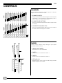
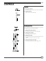
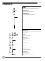
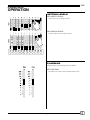
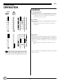
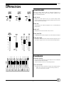
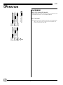
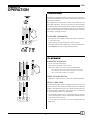
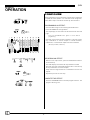
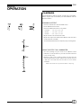
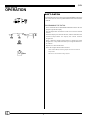
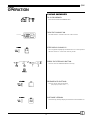
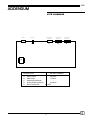
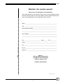
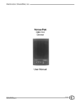
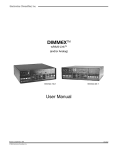
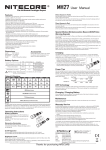
Lite Lite Control Console with Soft-Patch User Manual 070-0630 Revision 7, December, 2000 © 2000, Electronics Diversified, Inc. 1 Lite INTRODUCTION ABOUT THE LITE CONSOLE TABLE OF CONTENTS We have all heard the phrase and we can recognize the value of the idea, "Keep it simple.....". Frankly, there is nothing wrong with the idea of good, simple, economic performance controls for the lighting market. The problem has been that no one has focused on something that is high quality and easy to operate. That was yesterday. This is today. The Lite Console is designed specifically as a "basis preset" control console. The concept of two-scene preset operation has been a tradition in the entertainment industry for over thirty years. This method of control provides a foundation for training new board operators as well as an easily recognized format for operation by people who have more responsibilities than time. The Lite Console is simple to operate. With direct control of the channels through manual sliders, bump buttons as well as crossfaders, and six independent submasters operating on three pages of memory, the Lite Console offers features which exceed the normal "simple control" operation. In addition to standard controls, the Lite Console offers illuminated bargraph displays of fader positions with crossfader timers for delayed or timed manual crossfades. The channels LED's located above the bump buttons, mimic proportional channels levels which are active through the crossfaders or illuminated by the submasters. Tricolored LEDs under the submasters indicate which page is active as well as which memory is blank. The Lite Console also offers an Effects package specifically designed to repeat patterns of light for special dramatic effects. The Effects package is straight forward and user-friendly for simple or complex application. Finally, the Lite Console is fast. This means that when you touch the bump button, you get an immediate response. Meeting expectations is what makes the Lite Console simple. We think that's the way it should be. OVERVIEW Front Panel . . . . . . . . . . . . . . . . . . . . . . . . . . . . . . . . . . . . . . . 3 Rear Panel . . . . . . . . . . . . . . . . . . . . . . . . . . . . . . . . . . . . . . . . 3 CONTROLS Channel . . . . . . . . . . . . . . . . . . . . . . . . . . . . . . . . . . . . . . . . . . 4 Fader . . . . . . . . . . . . . . . . . . . . . . . . . . . . . . . . . . . . . . . . . . . . 4 Submaster . . . . . . . . . . . . . . . . . . . . . . . . . . . . . . . . . . . . . . . . 5 Bump . . . . . . . . . . . . . . . . . . . . . . . . . . . . . . . . . . . . . . . . . . . 6 Effects . . . . . . . . . . . . . . . . . . . . . . . . . . . . . . . . . . . . . . . . . . . 6 PRESET 2-SCENE OPERATION Setting Levels . . . . . . . . . . . . . . . . . . . . . . . . . . . . . . . . . . . . . 7 Playback . . . . . . . . . . . . . . . . . . . . . . . . . . . . . . . . . . . . . . . . . 7 BUMP OPERATION Configure . . . . . . . . . . . . . . . . . . . . . . . . . . . . . . . . . . . . . . . . . 9 Playback . . . . . . . . . . . . . . . . . . . . . . . . . . . . . . . . . . . . . . . . 10 SUBMASTER OPERATION Configure . . . . . . . . . . . . . . . . . . . . . . . . . . . . . . . . . . . . . . . . 11 Playback . . . . . . . . . . . . . . . . . . . . . . . . . . . . . . . . . . . . . . . . 11 EFFECTS OPERATION Configure . . . . . . . . . . . . . . . . . . . . . . . . . . . . . . . . . . . . . . . . 12 Playback . . . . . . . . . . . . . . . . . . . . . . . . . . . . . . . . . . . . . . . . 13 SOFT-PATCH OPERATION Soft-Patch . . . . . . . . . . . . . . . . . . . . . . . . . . . . . . . . . . . . . . . 14 Programming the Patch . . . . . . . . . . . . . . . . . . . . . . . . . . . . . 14 CLEAR OPERATION Clear Memory . . . . . . . . . . . . . . . . . . . . . . . . . . . . . . . . . . . . 15 This User Manual is supplied with your system. Copies of this manual may be obtained from Electronics Diversified, Inc. for a nominal charge. It is recommended that you copy those portions of this manual applicable to your present use in the installation, maintenance or repair and preserve the original in a safe place. © 1998, by Electronics Diversified, Inc. All rights reserved. No part of this manual may be reproduced by any means, graphic, electronic, or mechanical, including photocopying, recording, taping, or information storage and retrieval systems, without the express written permission of Electronics Diversified, Inc., except in connection with installation, repair and maintenance of Electronics Diversified, Inc. systems. ACCESSORIES Console Cables . . . . . . . . . . . . . . . . . . . . . . . . . . . . . . . . . . . 16 TECHNICAL SPECIFICATIONS Protocol . . . . . . . . . . . . . . . . . . . . . . . . . . . . . . . . . . . . . . . . . 17 ADDENDUM Lite Front Panel . . . . . . . . . . . . . . . . . . . . . . . . . . . . . . . . . . . 18 Lite Chassis . . . . . . . . . . . . . . . . . . . . . . . . . . . . . . . . . . . . . . 19 SERVICE Information . . . . . . . . . . . . . . . . . . . . . . . . . . . . . . . . . . . . . . . 20 Registration . . . . . . . . . . . . . . . . . . . . . . . . . . . . . . . . . . . . . . 21 2 Lite OVERVIEW FRONT PANEL 1 7 8 2 1. POWER SWITCH: 3 Located in rear. 2. POWER INDICATOR: Illuminated when console is On. 3. CHANNEL CONTROLS: Two-scene channel controllers for individual level setting. EFFECTS MODE RUN POWER BUMP MASTER DIR PAGE F 1 STOP B 2 OFF R 3 PROGRAM 4. BUMP BUTTONS: 1 2 3 4 5 6 7 8 9 10 11 12 13 14 15 16 17 18 19 20 21 22 23 Channel bump buttons with mimic level indicators. 24 RATE S C E N E 5. PLAYBACK CONTROLS: 1 1 2 3 4 5 6 7 8 9 10 11 12 13 14 15 16 17 18 19 20 21 22 23 Split dipless crossfaders with timer controls. Bump mode Switches: On, Off, and Solo. Effects Master and Rate Controls. Grand Master and Blackout switch. 24 S C E N E 2 GM EM STEP/HOLD 6. SUBMASTERS: Three pages of overlapping submaster memories with bump buttons and tricolored LEDs. 7. EFFECTS CONTROLS: 6 Program controls for Chase effects to include Mode direction and Page selections. 4 5 8. PROGRAM KEY: For recording Submaster memories. For recording Effects memories. For recording Soft-Patch. REAR PANEL 1. CONSOLE POWER MODULE: 3 2 On/Off Switch. Fuse Carrier (.5 Amp). Grounded recessed IEC connector for console power. 1 2. DMX512 OUT: Console output locking 5-pin XLR connector. 3. ANALOG OUTPUT PORTS: 25D connectors for 0- +10 VDC output. (12- 24- 36- 48- 0r 60-channel capacity). 3 Lite CONTROLS CHANNEL Control channels represent a single or group of dimmers assigned to a linear slider for output. 1. CHANNEL SLIDERS: Twenty-four (24) channel sliders arranged in a 2-Scene preset configuration. Twelve channels are represented by fader 1, and 12 channels are represented by fader 2. 2. CHANNEL BUMP BUTTONS: Twelve (12) individual bump buttons for direct output control of channels. 1 3. ILLUMINATED CHANNEL LEDs: Twelve (12) individual channel LEDs mimic the level output of the channel directed through the crossfader. 2 3 FADER Control console channels output through a split dipless crossfader between scenes. 1. CROSS FADE TIMERS: Sets fade time for associated faders. 1 2. FADER 1: Controls levels set on channels in Scene 1. 3. FADER 2: Controls levels set on channels in Scene 2. 2 3 4. LED DISPLAYS: Bargraph displays active position of fader during crossfade. Displays progress of time fades. 4 4 Lite CONTROLS FADER 5. BLACKOUT SWITCH: In the BLACK position, all levels are forced to Off immediately. 5 6. GRAND MASTER: Controls overall console output level. 6 SUBMASTER Control submasters represent a channel or group of channels with individual levels controlled as a group. 1 1. SUBMASTER PAGE SWITCH: The 3-position switch selects active memory page. 2. SUBMASTER SLIDERS: Six individual Pile-on memory faders. 2 3. SUBMASTER LED's: Tri-colored LED announces which memory page is active on the sider. NOTE: If the Submaster is empty, LED will not light. 4. SUBMASTER BUMP BUTTONS: 3 Six individual bump buttons for direct output control. 4 5 Lite CONTROLS BUMP Bumps allow direct output outside the fader position. 1. MODE SWITCH: 1 Selects Solo, On, Off bump functions. 2. BUMP MASTER: Controls output level for bump functions. 2 EFFECTS 1 2 Controls are used to program an Effect, Rate, and EM control playback of effect. 3 1. MODE: Activates Effect playback. 2. DIRECTION: Selects effect direction. 4 3. PAGE : Selects effect to be played. 4. EFFECT RATE: Selects the effect rate. 5 5. STEP: Displays the current step of the effect. 6. EFFECT MASTER: 6 Controls effect output level. 7. STEP/HOLD: Stops a running effect. Steps a stopped effect. Used when programming an effect. 7 6 Lite 2-SCENE PRESET OPERATION SETTING LEVELS SET SCENE 1 LEVELS: Selects Solo, On, Off bump functions. SET SCENE 2 LEVELS: Controls output level for bump functions. PLAYBACK Playback each scene through the crossfaders. SET FADE TIME: Set Fader Time sliders to desired fader playback time 7 Lite 2-SCENE PRESET OPERATION PLAYBACK SET GRAND MASTER: 00 Set Grand Master at Full. The Grand Master will control the overall output of the console (Channels, Submasters, Effects). The Blackout Switch, when activated (set to BLACK), will instantly force all levels to '0' output. PLAY SCENE: Move Crossfader 1 to position 10. Bargraph will follow based on set Fader Time. LED mimic lights will show levels set when a scene is active with Crossfader UP. CROSSFADE: Move both Faders together in the same direction. One moves to '0', the other moves to '10'. Bargraphs follow according to set fade time. When the crossfade from Scene 1 to Scene 2 is complete, the fader LED display in Scene 2 will be fully illuminated. LED mimic lights will show channel levels set when a scene is active. Scene 1 is ready to be configured for the output levels required for the next scene. 8 Lite BUMP OPERATION CONFIGURE Pressing a Bump Button adds an individual Channel or a Submaster Channel into the console output, based on the level of the Bump Master. BUMP SOLO: Bump Solo mode outputs levels as in normal bump mode, except all channels not involved with the bump are held at zero for the duration of the bump. BUMP ON: Normal bumps are enabled. Playback level is controlled by the Bump Master. BUMP OFF: Bump buttons are deactivated on the console. BUMP MASTER: The Bump Master sets the output level for the channels bumped. BUMP BUTTONS: The buttons under the channel sliders allow the operator to force the channel output to the level selected on the Bump Master. PLAYBACK CHANNEL BUMPS: Press the Channel Bumps to set the output level of an individual Channel into the console output. Output is based on the level of the Bump Master. HOLD THE BUMP: The output level stays constant as long as you hold the button. HINT: If the channel level is at 25% and the Bump Master is at FULL, the bumped level is at 100% 9 Lite BUMP OPERATION PLAYBACK PRESS THE SUBMASTER BUMPS: Submaster Bumps set the output level of all the channels stored in the Submaster to the level of the Bump Master. HOLD THE BUMP: The output level stays constant as long as you hold the button. HINT: If the channel level is at 25% and the Bump Master is at FULL, the bumped level is at 100% 10 Lite SUBMASTER OPERATION CONFIGURE Submasters operate outside the control of the cross faders. The Submaster Page Switch controls the position of the active submaster memories. Each page allows an individual memory to be stored on each individual submaster. The result is 6 memories for each page. The LED located under the Submaster slider coordinates with the color labeled on the Submaster page switch. Submasters without an active LED color under the handle have no memory recorded to the Page position. TO RECORD A SUBMASTER: Set output levels on channel or submaster sliders in either Scene 1 or Scene 2 mode. Yellow Select Submaster page number (Red; Yellow; Green). Press Bump button under Submaster to be stored, then press PROGRAM button while holding Submaster bump. PLAYBACK SUBMASTER OPERATION: Select active Submaster page. Move Submaster Slider to desired level. Submaster outputs are controlled by the Grand Master. Submasters operate on a 'highest takes precedence' basis with the Crossfaders. If the channel level is set higher on the manual output, the Submaster output will not appear. PRESS THE BUMP BUTTON: Submaster output level will be controlled by the Bump Master. SELECT A NEW PAGE: The Submaster page can be changed even when sliders are active or inactive. This allows active Submasters from different pages to be played at the same time. When a Submaster from a previous page is returned to a '0' position, the current page is automatically loaded to the Submaster. The LED under the Submaster is coordinated with the color label next to the page switch. An active Submaster LED indicates the page source of the memeory. If active LED is not illuminated, no record is established in the Submaster. 11 Lite EFFECTS OPERATION CONFIGURE Effects programs consist of a series of steps which sequence or repeat the same pattern. For the best visual recognition, Chase Effect steps should be divisible by the number 3. PROGRAMMING AN EFFECT: Select the Effect Page for record using the PAGE switch. Press PROGRAM until the light blinks. P2 The step display will now show P2 which reflects the selected page. Press the PROGRAM button again to cancel Effects programming. Select the "look" for the first step of the effect. The look may be any combination of console outputs to include channels, submasters, or combination outputs from the Crossfader. (99 steps per Effect, maximum). RECORDING AN EFFECT: With the "look" output active, press the STEP/HOLD button to record the step. The STEP display will indicate the step number recorded. Select the next "look" for the 2nd step of the effect. The look may be any combination of console outputs. A step can be a single channel or a combination of active level outputs. 02 Repeat the process for each step. COMPLETE THE EFFECT: Press the PROGRAM button to end the program function. The program LED will go out. 12 Lite EFFECTS OPERATION PLAYBACK Like Submasters, Effects operate outside the Crossfaders. Effects outputs are controlled by the Grand Master and the Blackout Switch RUNNING AN EFFECT: Select the desired effect with the PAGE switch. Set the MODE switch to RUN. Select the DIRECTION switch to set pattern: Forward -- 1, 2, 3, 1, 2, 3, 1, 2, 3 Bounce -- 1, 2, 3, 2, 1, 2, 3, 2, 1 Reverse -- 3, 2, 1, 3, 2, 1, 3, 2, 1 Adjust the effect rate with the Rate slider. Adjust effect output level with the Effect Master slider. The effect can be faded UP or DOWN. Use the STEP/HOLD button to temporarily stop a running effect. USING THE EFFECT AS A SUBMASTER: The effect package may be used as an additional timed submaster. To use this function, you must record an effect that is only one step long. When the mode is set to RUN or STOP, the effect may be controlled by the Effect master, and the rate slider will allow for a fade time. The fade times are the same as for a normal crossfader. NOTE: This function will only work if the effect is 1 step long. 13 Lite SOFT-PATCH OPERATION SOFT-PATCH The Soft-Patch allows you to assign individual DMX512 dimmers to a control channel. You may patch DMX512 dimmers between 1 and 96. PROGRAMMING THE PATCH: Press and hold both the PROGRAM and STEP buttons until the program light blinks rapidly. Use the Step button and direction switch to select the desired number. The STEP display will show the dimmer, and the LED above the channel bunp buttons will display the current channel assignment. Press a different channel bump button to change the patch assignment, or any Submaster bump to assign the dimmer to no channel. Repeat for all desired dimmers Press the Program button when finished. When in Patch Mode, the analog outputs will mimic the channel bump LED's. 12 NOTE: You cannot Patch Analog outputs! 14 Lite CLEAR OPERATION CLEAR MEMORY TO CLEAR MEMORY: Press and hold the PROGRAM button. TURN THE CONSOLE ON. The ON switch is located in the rear of the console. ON Switch STEP DISPLAY SHOWS 'CL': CL The 7-segment step display window shows "CL" to alert operator that the console is in the erase memory mode. PRESS THE STEP/HOLD BUTTON: This will erase all Submaster/Effects memory. RELEASE BOTH BUTTONS: This will restore normal operation. -- (Step display window shows "- -".) SOFTWARE VERSION: On Power Up, the Step display will show the version Number 3.0. 3.0 15 Lite ACCESSORIES SOFT CONSOLE COVER: Designed to keep your Lite clean, dust free, and protect the control surface. EDI Part Number: 12-Channel 202-0064 24-Channel 202-0065 EDI Part Number: 36-Channel 202-0066 48-Channel 202-0067 EDI Part Number: 60-Channel 202-0068 EDI Part Number: HARDCASEXX EDI Part Number: 25CC 5XLR EDI Part Number: 25CC 25D EDI Part Number: DMXRCU EDI Part Number: 020-0969 HARD CONSOLE CASE: Tough, durable locking travel case for transport, or storage of your Lite. DMX CONTROL CABLE: The standard DMX-512 Data Cable is furnished with a 5-pin XLR style locking connector, 25' in length. Custom lengths are available on request. ANALOG CONTROL CABLE: The standard Analog Control Cable is furnished with a 25- pin D style connector with locking tabs, 25' in length. Custom lengths are available. DMX REMOTE CONTROL UNIT: Allows direct dimmer access for focus or dimmer checks without the control console on line. This small, hand-held, battery powered unit simply plugs into the existing DMX-512 data line for operation. DMX WINDOWS KIT: DMX Windows Kit converts the USITT standard DMX-512 signal into a Super VGA monitor signal directly compatable with any VGA Color Monitor. (Monitor sold separately) 16 Lite TECHNICAL SPECIFICATIONS PROTOCOL Lite consoles are available with two distinct types of dimmer address protocols identified as: DMX-512 PROTOCOL: DMX-512 is based on USITT standards. Connector: 5-pin XLR locking type Keyed connector style Up to 512 dimmer addressed on a single connection All control pins are numbered. (See 5XLR pin detail illustration). DMX-512 control is a digital signal transmitted over the control cable. TO INSURE PROPER CONNECTION: Physically inspect connectors prior to mating. Rotate connector to insure key alignment. 5 4 3 Connectors should mate easily. Do not force. 2 5XLR Output Pin Configuration ANALOG CONTROL PROTOCOL: Analog Output: 0-10 Volts DC, 5 mA. Connector: 25D chassis mount connector Up to 24 channels of address are available in a 25D connector. 24-Channel Output Pin Configuration (See 25D pin detail illustration) Analog control requires a wire in the D25 connector and cable for each dimmer addressed. TO INSURE PROPER CONNECTION: Physically inspect connectors prior to mating. Connectors should mate easily. Do not force. Always tighten locking screws on connector. 17 Lite ADDENDUM LITE FRONT PANEL Legend: 6-position Dip Switch: (Setting per Circuit Board shown) Connector Battery Socketed IC with Direction Indicated 1 2 A B #1 3 1234 1234 1234 1234 1234 C D #2 F E #3 #4 12345678901 123456789012345678901 123456789012345678901 12345678901234567890 12345678901 123456789012345678901 12345678901234567890112345678901234567890 12345678901234567890 12345678901 123456789012345678901 123456789012345678901 1234567890123456789012345678901234567890 12345678901234567890 12345678901123456789012345678901 1234567890123456789011234567890123456789012345678901234567890 12345678901 123456789012345678901 1234567890123456789011234567890123456789012345678901234567890 DESCRIPTION 1 2 3 A B-F #1-#5 EDI PART NUMBER Power Connector on CPU card. DMX Output on CPU Card. Battery CPU Board Channel Modules Address settings per circuit board 18 --RAY-O-VAC BR2032 670-8899 670-8891 #5 Lite ADDENDUM LITE CHASSIS POWER A DMX OUT HOUSELIGHTS (Optional) ANALOG OUT (Optional) C B D E DESCRIPTION A B C D E EDI PART NUMBER Power Switch 020-4001 DMX Output 179-0501 Houselights (Optional) -Analog Output (Optional) 020-4004 Power Transformer 120-0070 19 ANALOG OUT (Optional) D Lite SERVICE EDI offers a 24 hour Service / Support Network. For technical questions about this product or operational assistance, ask for Customer Service at: . . . . . . . . . 1-800-547-2690 You may communicate by FAX: . . . . . . . . . . . . . . . . . . . . . . . . . . . . . . . . . . . . . . . . . . . . . . . . . . . . . . . . . . . . . . . 1-503-629-9877 After Hours Emergency contact: . . . . . . . . . . . . . . . . . . . . . . . . . . . . . . . . . . . . . . . . . . . . . . . . . . . . . . . . . . . . . . . 1-503-645-5533 Ask for Emergency Assistance. Internet: . . . . . . . . . . . . . . . . . . . . . . . . . . . . . . . . . . . . . . . . . . . . . . . . . . . . . . . . . . . . . . . . . . . . . . . . . . . . www.edionline.com Internet E-Mail: . . . . . . . . . . . . . . . . . . . . . . . . . . . . . . . . . . . . . . . . . . . . . . . . . . . . . . . . . . . . . . . . . . . . . . . . . . . . [email protected] If your Lite console needs repair, call 503-645-5533 for a Return Materials Authorization number, and a shippping address will be furnished. This console is a product of: 1675 N.W. Cornelius Pass Road, Hillsboro, Oregon 97124 USA 20 Lite Attention Lite console owners! Please return this registration card immediately. Your prompt attention to this matter will ensure your receiving updated technical information for this product as it becomes available. Please complete all information. Look for acknowledgment of your registration within 6-8 weeks. Name: _______________________________________________________ Title: ________________________________________________________ Facility and/or Company: ________________________________________ _____________________________________________________________ Street Address: _______________________________________________ _____________________________________________________________ City: ____________________________ State: ______ Zip: __________ Phone: ______________________________________________________ E-mail: ______________________________________________________ Web site: ____________________________________________________ Mail to: EDI User Manual Registration 1675 NW Cornelius Pass Road Hillsboro, Oregon 97124 ! CUT ALONG DOTTED LINE Fax: _________________________________________________________ or FAX to: (503) 629-9877 Revision 2, May 1998 21