1
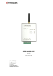
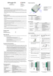
GSM module G10 Module G10 is designed to transmit messages from security control panel in a secured object to a monitoring station through a GSM connection. Module features: Messages to the monitoring station can be transmitted through GPRS, CSD connection or with SMS messages; Messages are sent through a communication channel set as primary and in case of connection failure – through a backup channel; Even though the GPRS connection with two servers will be lost, information can be sent in SMS messages; Sent messages correspond with Contact ID protocol codes; SMS messages can be sent to 4 user mobile phones; Output OUT1 status can be controlled remotely; Operating parameters and firmware version can be updated remotely; Operating parameters are set with program G10config. Description of device operation When connected to a DSC, Caddx, Paradox or Pyronix security control panel data bus, the module receives its messages and transmits them to monitoring station over set communication channel. If a message fails to be transmitted through this communication channel, the module can send the message through a backup channel. If there are set 2 IP addresses and module loses GPRS connection with them, information can be sent to monitoring station in SMS messages. The module can send messages to specified recipients about breaking/restoring external circuit of inputs IN1 and IN2. The module can periodically send signals PING for controlling the connection. Messages can be sent with SMS messages to 4 mobile phones. There is possible assign understandable text to every security control panel event. Module output OUT1 state will change when connection with the monitoring station server fails/restores or when the module receives an SMS message containing of command to change its output state. Module components 1 – Terminal block 2 – SIM card holder 3 – USB socket 4 – GSM antenna 5 – indicator “Network” 6 – indicator “Data” 7 – indicator “Power” Terminal block description Contact +E COM CLK DATA IN1 OUT1 IN2 COM MCI Purpose +12V power supply clamp Common clamp Synchronizing signal clamp Data signal clamp 1st input clamp (NC type) Output clamp (OC type) 2nd input clamp (NC type) Common clamp Provided for future use Light indication LED Network displays connection with GSM network status Data displays data buffer status Operation Green ON Yellow ON Green flashing Yellow flashing Green ON Description Module is connected to GSM network Message is being sent Connecting to GSM network Number of yellow flashes represent GSM signal strength Unsent messages present in module memory Power displays power supply status, functioning of microcontroller and programming status. Red ON Green flashing Red flashing rapidly Red flashing Green flashing Yellow flashing Green and yellow flashing in turn Unable to be sent messages Messages are being received from the control panel SIM card error Module configuration is incorrect Power supply is sufficient, microcontroller is functioning Power supply is not sufficient (≤11,5 V), microcontroller is functioning Programming mode 3