1
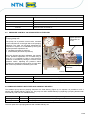
7.4.4 Procedure for calibrating the ultrasound probe model ZWS-70/CI/QS (code 3289173)
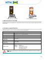
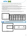
Before being assembled the probe must be calibrated in accordance with the following sequence:
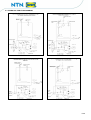
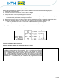
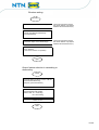
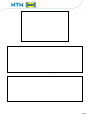
1. electrically connect the sensor (following the electric diagram shown below);
2. keep the sensor button pressed down until the two LED (green and yellow lights) flash together;
3. position it in front of the minimum absolute level to be read, entering the height by releasing the button (the two
LEDs display a fixed light);
4. press the button for 3 or 4 seconds (the probe has acquired the Minimum absolute level);
5. keep the sensor button pressed down until the two LED (green and yellow lights) flash together;
6. position it in front of the maximum absolute level to be read, entering the height by releasing the button (the two
LEDs have a fixed light);
7. press the button for 3 or 4 seconds (the probe has acquired the Maximum absolute level);
8. In this way the sensor is calibrated.
N.B.: green Led on indicates that the probe is supplied. Yellow Led on indicates operating mode for reading.
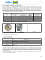
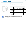
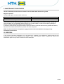
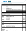
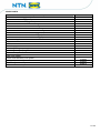
We attach a table with the calibration parameters for the ultrasound probe, for 30 and 100 kg tanks.
Calibration of ultrasound probe
Pos.
30 kg tank
Level
A
Picture 18
B
Output
signal
Maximum
Threshol
absolute
d1
level
Minimum
threshold
absolute
2
level
100 kg tank
height X
[mm]
Quantity of
grease [kg]
50
26
50
95
420
0
800
0
height X Quantity of
grease [kg]
[mm]
N.B.: In the 30 kg pump tank at the minimum absolute level there is still a reserve of 7 kg.
In the 100 kg pump tank at the minimum absolute level there is still a reserve of 15 kg.
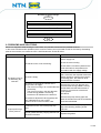
Green LED: status indicator.
Signals if the sensor is powered.
Yellow LED: function indicator.
Reports the output status (On/Off).
Picture 20
Picture 19
15/ 26