1
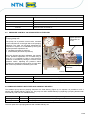
7.4.2 Procedure for calibrating the capacitive probe
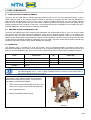
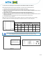
Before being assembled the capacitive probe must be calibrated in accordance with the following sequence:
1. connect the sensor electrically;
2. immerse the sensor in the lubricant, down to half of its length;
3. remove the sensor from the lubricant until it skims the surface of the lubricant;
4. at this point there can be two possible types of operation:
• the sensor status does not change: its sensitivity must be reduced (by acting on the screws for adjusting
sensor sensitivity) until its state of excitation is reached
• if its status changes, the sensor already possesses the correct sensitivity
5. after checking that the sensor has been correctly read, the sensor reading must be repeated at least three times
6. Tighten the capacitive probe on the probe carrier rod, complying with the following assembly height:
•
450 mm (from below the cover up to the lower surface of the sensor) for a 30 kg tank
•
900 mm (from below the cover up to the lower surface of the sensor) for a 100 kg tank
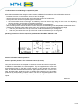
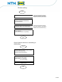
Operating instructions for the capacitive probe (model SC18M-C5 PNP NO + NC)
Picture 14
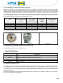
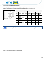
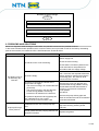
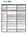
General information about operations
Sensors operating under C for continuous current (4 wires)
They are sensors which are amplified in continuous current and which incorporate,
in addition to the oscillator, the outlet amplifier. They are supplied with 4 wires with
an antivalent function in the NPN or PNP versions. In this operation the sensors
offer as standard characteristics protection against permanent short circuit of the
load, absolute safety against inversion of polarity and protection from the peaks
produced by disconnecting inductive loads. They can be supplied together with
model ALNC – ALTP feeders. They are compatible with programmable controller
inputs.
Picture 15
12/ 26