1
SVR Series
Veilux H.264 Digital Video Recorder
Website: www.veilux.net
Phone # 1-800-510-6528
VEILUX USER’S MANUAL
SVR Series
Release Version
INDEX
Chapter 1. Installation
Contents of the box
5
Choosing a location for installation
5
Installation
6
Rear panel layout
6
Basic connections
6
Connect audio devices (optional)
7
Connect alarms (optional)
7
Connect RS-485 PTZ camera (optional)
7
Connect to network (optional)
8
Connect a mouse (optional)
8
Connect power
8
Time adjustment
9
Chapter 2. Pre-acknowledgement
Front panel
10
Infrared remote controller
11
Mouse operations
12
Virtual keyboard
13
Login
13
User management
14
Daylight saving time (DST)
15
Shutdown (Auto power off)
16
Chapter 3. Operation
View panel
17
Camera pane
17
Status bar
18
Panic mode (emergency recording)
20
Live monitoring
21
Single-screen display
21
Page 2 of 69
Multi-screen display
22
Audio volume control
23
PTZ (Pan / Tilt / Zoom)
24
Search & Playback
26
Playback control
26
Quick play
28
OSD on/off_______
29
Entering to search mode
30
Calendar search
30
Event search
32
Backup
33
Backup device
33
Backup file type
33
Entering to backup menu
33
Backup
34
Chapter 4. Setup
Summary
35
Record settings
36
Record :: Setup
36
Record :: Network
37
Record :: Schedule
38
Record :: Holiday
39
Camera settings
40
Camera :: Setup
40
Camera :: Motion
41
Camera :: PTZ
42
Camera :: Keyboard
43
Event settings
44
Event :: Alarm In
44
Event :: Alarm Out
45
Event :: Email
46
Event :: Beep
47
Display settings
48
Page 3 of 69
Display :: Screen
48
Display :: Spot
49
Storage settings
50
Storage :: Storage
50
Storage :: S.M.A.R.T.
51
Storage :: Record
52
Storage :: Backup
52
System settings
53
System :: Network
53
System :: DDNS
54
System :: Server
56
System :: Log
57
System :: User
57
System :: Info
58
System :: Email
59
System :: Time Sync.
60
System :: Etc
61
Chapter 5. Service Menu
Entering to service menu
62
Service :: Upgrade
62
Service :: Config
63
Service :: Format
63
Service :: DateTime
63
Service :: Etc
64
Appendix 1. Menu tree
65
Appendix 2.
67
Factory default setting
Page 4 of 69
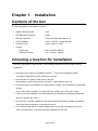
Chapter 1. Installation
Contents of the box
The following parts are included in the box.
▪
Digital Video Recorder
1 unit
▪
CD (Manual & Program)
1 piece
▪
Remote Controller
1 unit (Including AAA battery x 2)
▪
AC/DC adapter
1 piece (12V/5A, 110Vac/220Vac)
▪
AC power cord
1 piece (220V or 110V)
▪
Screws
-
HDD screw
2 kits / 8 pieces (#6-32)
-
DVD-R/W screws
1 kit / 4 pieces (M3x6)
Choosing a location for installation
The unit is designed for desk mount. The following precautions must be taken during
installation.
▪ Openings in the case are ventilation purpose. To prevent overheating, these
ventilation holes should not be blocked or covered.
▪
Ensure there is 2” gap on either side of the unit.
▪ When stacking units, ensure there is at least 1” gap between each unit.
▪
Ensure the unit is not located in an area where it is likely to be subjected to mechanical
shocks.
▪ The unit should be located in an area with low humidity and a minimum of dust.
▪
If the unit is to be installed in a closed assembly, the maximum operating temperature
Must not exceed 104℉(40℃)
▪
Ensure there is reliable earthling of the mains outlet when fitted to supply connections,
other than direct connection, to the branch circuit.
▪
It is recommended that an uninterruptable power source be connected to the unit in
case of power failure, to ensure continuous operation of the unit.
Page 5 of 69
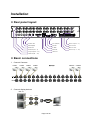
Installation
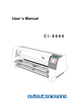
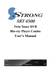
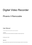
Rear panel layout
MAIN
OUT
VIDEO
1
2
3
4
5
6
7
8
9
10
11
12
13
15
14
16
SPOT
OUT
LOOP
OUT
COM
R4/NO
COM
R4/NC
R3/NO
R3/NC
DC 12V
R2/NO
RS-485
+ -
R2/NC
E-SATA
R1/NO
ETHERNET
ALARM OUT
R1/NC
VGA
IN15
IN16
GND
S-VHS
IN11
IN12
GND
IN13
IN14
MOUSE
PS2
GND
AUDIO AUDIO
IN 4
OUT
ALARM IN
IN9
IN10
AUDIO
IN 3
GND
AUDIO
IN 2
IN1
IN2
IN3
IN4
AUDIO
IN 1
IN5
IN6
IN7
IN8
ALARM IN
S-Video Out
DC (12V/5A)
Alarm out(# 1 ~ 4)
Mouse(PS/2)
RS-485
Spot TV Out
Audio Out
E-SATA
Main TV Out
Audio In(Ch1 ~ 4)
Ethernet
Alarm In (# 1 ~ 16)
Loop Out(Ch1 ~ 16)
VGA Out
Video In(Ch1 ~ 16)
Basic connections
1.
Connect Cameras
CAM#1
CAM#2
CAM#3
CH1
CH2
●●● ●
CAM#4
CH3
CH4
CH5
CH6
CH7
CAM#15
CH8
CH9
CH10
CH11
CAM#16
CH12
CH13
CH14
VIDEO IN
2.
Connect display devices
LOOP OUT
Main TV
H10
CH11
CH12
CH13
CH14
CH15
MONITOR
CH16
AUDIO
IN 1
IN 2
IN 3
IN 4
OUT
PS/2 MOUSE
S-VHS
VGA
RS-232C
POWER
VGA Monitor
SPOT OUT
Spot TV
e-SATA
RS-485
DC 12V
ALARM IN
1 2 3 4 G 5 6 7 8 G
9 10 1112 G 13 14 15 16 G
ALARM OUT
N N N N
COCO
CAUTION
WARNING
Page 6 of 69
N N N N
COCO
MADE IN KOREA
ETHERNET
e-SATA
RS-485
DC 12V
1 2 3 4 G 5 6
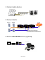
Connect audio devices
VIDEO
1
3
4
5
6
MOUSE
PS2
S-VHS
AUDIO
IN 1
AUDIO
IN 2
AUDIO
IN 3
AUDIO AUDIO
IN 4
OUT
15
14
Sensor#8
Sensor #9 ~
COM
R4/NO
COM
R3/NO
R3/NC
R2/NO
R2/NC
ALARM OUT
R1/NO
GND
ALARM IN
IN9
IN10
GND
DC 12V
IN5
IN6
IN7
IN8
RS-485
+ -
IN1
IN2
IN3
IN4
E-SATA
Alarm
#1 ~ #4
SPOT
OUT
ALARM IN
THERNET
ETHERNET
16
R1/NC
~
13
IN15
IN16
GND
Sensor #1
12
VGA
MAIN
OUT
IN11
IN12
GND
IN13
IN14
11
This drawing is for N/C type device.
If you have N/O type, then connect to N/O pin.
Sensor #16
MAIN
OUT
Connect RS-485 PTZ camera (optional)
7
8
9
10
9
Speaker
Connect alarms
10
8
11
12
13
15
14
16
SPOT
OUT
ALARM IN
ALARM IN
ALARM OUT
Page 7 of 69
COM
R4/NO
R4/NC
COM
R3/NO
R3/NC
R2/NO
R2/NC
R1/NO
R1/NC
IN15
IN16
GND
IN11
IN12
GND
IN13
IN14
GND
DC 12V
IN9
IN10
RS-485
+ -
GND
E-SATA
IN5
IN6
IN7
IN8
ETHERNET
IN1
IN2
IN3
IN4
PTZ Camera
VGA
10
LOOP
OUT
Microphone
Pre-amplifier
9
7
R4/NC
Microphone #1~#4
2
E-SATA
MAIN
OUT
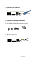
Connect to network
7
8
9
10
11
12
13
15
14
16
SPOT
OUT
ALARM IN
ALARM IN
ALARM OUT
COM
R4/NO
R4/NC
COM
R3/NO
R3/NC
R2/NO
R2/NC
R1/NO
R1/NC
IN15
IN16
GND
IN11
IN12
GND
IN13
IN14
DC 12V
GND
RS-485
+ -
IN9
IN10
E-SATA
GND
ETHERNET
IN1
IN2
IN3
IN4
VGA
IN5
IN6
IN7
IN8
RJ-45 Plug
Connect a mouse (optional)
The unit support hot plug-in & play.
So, you can attach the mouse later, during system is running.
2
4
5
6
7
8
9
10
11
12
13
15
14
ALARM IN
16
ALARM IN
A
Connect power
7
8
9
10
11
MAIN
OUT
12
13
15
14
16
SPOT
OUT
ALARM IN
ALARM IN
ALARM OUT
Page 8 of 69
COM
R4/NO
R4/NC
R3/NO
COM
R3/NC
R2/NO
R2/NC
R1/NO
R1/NC
DC 12V
IN15
IN16
GND
RS-485
+ -
IN11
IN12
GND
IN13
IN14
E-SATA
IN9
IN10
ETHERNET
GND
VGA
GND
DC Plug
(12V)
R1/NO
DC 12V
R1/NC
RS-485
+ -
IN15
IN16
GND
E-SATA
IN11
IN12
GND
IN13
IN14
ETHERNET
GND
VGA
IN9
IN10
S-VHS
IN5
IN6
IN7
IN8
MOUSE
PS2
IN1
IN2
IN3
IN4
AUDIO AUDIO
IN 4
OUT
IN5
IN6
IN7
IN8
AUDIO
IN 3
GND
PS/2 Wheel Mouse
IN1
IN2
IN3
IN4
IO
2
3
Time adjustment
TIME STAMP IS A VERY IMPORTANT REFERENCE FOR RECORDING AND SEARCHING.
PLEASE, SET CLOCK CORRECTLY AFTER READ THIS SECTION.
Step 1. Set GMT/Location
Since DST rule is different location by location, you must set your correct location.
Please, set correct GMT/Location in Admin::DateTime menu.
Refer to “Daylight Saving Time” section in Chapter 2.
Refer to “Admin::DateTime” menu in Chapter 5.
Step 2. Initial time synchronization in Admin menu (Optional)
If the unit can access network time server, it is recommended strongly to synchronize the time
with the network time server before start, in Service menu.
Because, if the time difference is big, then time synchronization is failed in recording mode.
You can do this job in Admin::DateTime menu.
Refer to Admin::DateTime menu in Chapter 5.
Step 3. Time adjustment
If you can‟t do step 2., the you need to adjust the time by your hand.
Refer to Admin::DateTime menu in Chapter 5.
Step 4. Periodical time synchronization (Optional)
You can configure the unit to synchronize the time periodically with network time server.
Refer to System::TimeSync. menu in Chapter 4.
Page 9 of 69
Chapter 2. Pre-acknowledgement
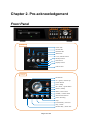
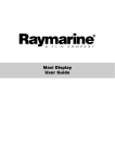
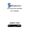
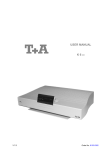
Front Panel
Group A
Group B
Group A
Power LED
Record LED
Network LED
Alarm LED
Lock / Unlock button
Backup button
PTZ button
Display button
USB 2.0 Port
Group B
IR Receiver
UP / Quad / Volume up
Power button
LEFT / 9Sep
OK / Enter / Quick Menu
RIGHT / 16Sep
Menu / ESC button
DOWN / Volume down
Search menu button
Panic recording
Stop
Forward Play / Zoom In
Play / Pause
Reverse Play / Zoom Out
Page 10 of 69
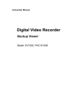
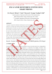
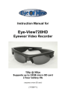
Infrared remote controller
Select Remocon ID
PANIC
1) Camera Select
2) Numeric Entry
1) Escape
2) Login
1) Up
2) 2x2 screen
3) Increase
1) Right
2) 4x4 screen
1) Left
2) 3x3 screen
1) Down
2) Volume Menu
3) Decrease
Menu
Search
Audio Mute
Forward play
Reverse play
Stop
Play/Pause
Prev. frame
Next frame
Backup Menu
Not Supported
Lock / Unlock
PTZ
Reserved for
future use.
Page 11 of 69
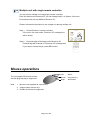
TIP
Multiple unit with single remote controller
You can control multiple unit using single remote controller.
Each unit has its own Remocon ID, you can change/verify it in System::Info menu.
Ensure that each unit has different Remocon ID.
Please, follow below procedure to set a target unit among multiple unit.
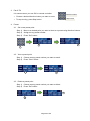
Step 1.
Press ID button in remote controller.
If the unit in live view mode, “Remocon ID” message box
will be shown.
Step 2.
Press two digit of the target unit‟s Remocon ID.
Pressed digit will be shown in “Remocon ID” message box.
If you want to cancel the job, press ESC button.
Mouse operations
The unit support PS/2 wheel mouse,
and hot-plug and play is supported.
Note
1.
Mouse is not supplied as a accessory.
2.
Support wheel mouse only.
3.
Double click does not supported.
Page 12 of 69
Left
: Select
Wheel
: Up(+)/Down(-)
Right
: Quick Menu
Virtual keyboard
In some menus, virtual keyboard served for text entry.
Escape
(Exit)
Back Space
Caps
Lock
Enter
Space
Large Letter mode
Multi Language Translator (Received)
Login
TIP Default password for all account is “11111111” (eight digit of „1‟).
When you try to access some function,
the unit will shows a login window,
and you have to login with proper permission
to access the unit.
Page 13 of 69
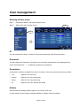
User management
Entering to User menu
Step 1.
Press Menu button, and select System menu.
Step 2.
Select User tab in System menu.
Step 2.
Step 1.
ID
You can rename from User1 to User15 using virtual keyboard, other ID are pre-fixed.
Password
You can change the password, mind that you must delete old password using backspace key
of the virtual keyboard. 1 ~ 8 digits are possible as a password.
Permission
4 permission levels are available from User1 to User18, other user‟s permissions are pre-fixed.
▪
Live
: Right for live view only.
▪
Search
: Right for live view and Search.
▪
Setup
: Right for live view and Setup.
▪
All
: Right for live view, Search and Setup.
Hidden
Administrator can assign different right to live view for each user.
In other words, all user could be assigned different “Hidden Camera” settings.
Page 14 of 69
Daylight Saving Time (DST)
The unit is embedding world DST rules, and it always enabled.
DST vs. Location
DST rule is totally depends on your location.
Please, set correct GMT/Location in “Service::DateTime” menu.
“Service::DateTime” means DateTime menu in Service menu.
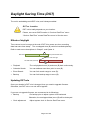
Effects of daylight
Time returns to one hour ago at the end of DST, this means one hour recording
data has same time stamp. The overlapped zone (B) could be handled optionally.
Refer to each menu descriptions in Chaptr 3. and Cpater 4..
A
DST term
End point of DST term
Back to one hour ago
No DST term (normal)
B
▪
Playback
: The unit playback zone (A) and zone (B) both continuously.
▪
Calendar Search
: You can address exact time point in zone (B).
▪
Event Search
: You can limit search range to zone (B).
▪
Backup
: You can limit backup range to zone (B).
Updating DST rule
Once your location‟s DST rule is changed, then you need to upgrade firmware.
Otherwise, last DST rule or no rule will be applied.
If you can not upgrade firmware, we recommend to do followings;
▪
Backup
: Do backup prior to adjust system clock backward.
Otherwise, the overlapped data (zone (B) will be destroyed.
▪
Clock adjustment
: Adjust system clock in Service::DateTime menu.
Page 15 of 69
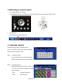
Shutdown (Auto power off)
Since the HDD contents could be damaged when HDD power is removed during access the
HDD, it is strongly recommended to follow shutdown procedures.
Step 1. Shutdown in menu
The unit prepares to shutdown when you choose
Shutdown in Quick menu.
Then appear login message box.
Enter „Admin‟ password.
Step 2.
Auto power off
The following appears “Do you want a shutdown?” message.
If you choose “Yes” then system is powered down
Page 16 of 69
Chapter 3. Operation
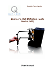
View panel
Recording mode
Camera name
Audio
Event status
Menu panel
Status bar
Camera pane
TIP
1.
You can show/hide the below items in Display::Screen menu.
Camera name
It shows camera name which is configured in Camera::Setup menu.
2.
Audio
It is shown when you enable the audio function in Camera::Setup menu.
Page 17 of 69
3.
Recording mode
It shows recording mode which is configured in Record:Schedule menu.
4.
Normal mode
Motion mode
Alarm mode
Alarm + Motion mode
Event status
It shows when some event was detected and recording is started.
There is no status in Normal mode.
Motion event
Alarm event
Motion and Alarm event (Both events are detected at same time)
Status bar
Log-in/out
Panic mode
Search menu
Backup status
Date & Time
Backup - Cancel
HDD status
Network status
Lock / Unlock
Menu button
1.
Menu button
Click this button to access Menu panel.
2.
Lock/Unlock
Click this button to Lock/Unlock mouse and front panel button operations.
Locked
Unlocked
Also, you able to locked through Quick menu.
3.
Search Menu
Click this button to enter into Search menu.
4.
Panic mode
Start to record immediately at any condition when press this button.
Login is required to stop Panic mode.
Panic mode
Normal mode
Page 18 of 69
5.
Backup status
It indicates that backup is in progress and its progressive rate in percentage.
6.
Date & Time
It shows current date & time in “YYYY-MM-DD HH:MM” format.
Atomic clock available through public network time server on internet.
TIP
See System::Time Sync. Menu in chapter 4. to use atomic clock.
7.
Network status
It shows count of network connection such as Web viewer and CMS.
“-“ means that network is disconnected.
8.
Log-in/out
It has two functions as below.
1)
Log-in/out button
Click to log-in(or log-out) to(from) the unit.
2)
User information
It shows log-in user name.
See System::User menu in Chapter 4. for user management.
TIP
Auto-hiding of status bar & Playback control bar
In the auto-hide mode, the status bar and playback control bar are shown/hidden
automatically.
1)
You can change the mode in Display::Screen menu.
Shown
▪ When move mouse pointer to bottom area of the screen.
▪ When press Menu button in front panel or remote controller.
2)
Hidden
It is hidden when above “Shown” condition is removed, and Show time is
passed.
Page 19 of 69
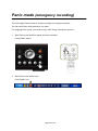
Panic mode (emergency recording)
The unit support Panic mode for instant recording in emergency situation.
You can start Panic mode whenever you want.
For stopping Panic mode, you need to log-in with “Setup” permission account.
1.
Start Panic mode with front panel & remote controller
Press PANIC button.
2.
Start Panic mode with mouse
Click PANIC icon.
Page 20 of 69
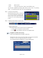
Live Monitoring
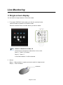
Single-screen display
You can watch a single camera in full screen mode.
1.
Front panel „DISPLAY‟ button when you click the continue button
camera number increases in full screen mode.
Remote controller Press a number button you want to watch.
TIP
Select a channel over than 10
Follow below procedures to select form ch11 to ch16.
Step 1)
Press “+10” button.
Step 2)
Press “1”.
In this case channel 11 will be selected.
2.
Mouse
Step 1)
Move pointer to a pane you want to watch in single screen.
Step 2)
Click Left button.
Left Button
Page 21 of 69
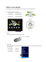
Multi screen display
The unit support multi screen display mode such as 2x2, 3x3 and 4x4 divisions.
1.
Front panel & Remote controller
2x2
▪ 2x2 division
: Press Up button
▪ 3x3 division
: Press Left button
▪ 4x4 division
: Press Right button
3x3
4x4
2x2
3x3
2.
4x4
Mouse
Click Left button at any location on the screen.
Left Button
2. Quick menu
Click Right button at appear the quick menu. One more click it same division that change
the next screen.
▪ 2x2 division
: Click 2x2
▪ 3x3 division
: Click 3x3
▪ 4x4 division
: Click 4x4
Page 22 of 69
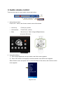
Audio volume control
There are two ways to control audio volume and muting.
Exit
Volume control bar
1.
Mute
Using Volume button
Press “VOL.” button, then Volume control menu will be shown.
▪ Volume up
: Press Up(+) button
▪ Volume down
: Press Down(-) button
▪ Mute
: Move focus to “Mute” using Left/Right buttons,
and press OK button.
2.
Using Quick Menu
1)
Click mouse Right button at any location, then Quick menu appears.
2)
Press “OK” button in front panel or remote controller, then Quick menu appears.
Select Volume menu and press “OK” or click Left button of the mouse, then Volume control
menu appears.
Page 23 of 69
PTZ (Pan / Tilt / Zoom) (Single screen mode only)
This facility works in following conditions;
▪
PTZ camera is connected to the desired channel.
▪
Model and Setting are correct in Camera::PTZ menu.
▪
RS-485 bus is working properly.
1.
Entering into PTZ mode
1.1 Press PTZ button in remote controller.
1.2 Use Quick menu.
2.
PTZ control panels
2.1 On screen control panel (GUI)
Pan & Tilt
Tour Duration
Tour Start
PTZ Speed
Exit
Delete preset
Set preset
Goto preset
Preset number
Zoom / Focus / Iris control
2.2
Key board control(Optional)
Page 24 of 69
3.
Pan & Tilt
It is same manner you use GUI or remote controller.
Direction button
▪ Choose a desired direction button you want to move.
Stop button
▪ To stop moving, press Stop button.
4.
Preset
4.1
Set a new preset point
Step 1)
Move to a desired point you want to store as a preset using direction buttons.
Step 2)
Assign an any preset number.
Step 3)
Press “Set” button.
3
2
1
4.2 View a preset point
Step 1)
Choose an any preset number you want to watch.
Step 2)
Press “Goto” button.
1
2
4.3 Delete a preset point
Step 1)
Choose an any preset number you want to delete.
Step 2)
Press “Del” button.
2
1
Page 25 of 69
Search & Playback
Two playback tools are served as below;
1) Quick Play
2)
: Instant playback in live mode, start from 10 minutes ago.
Search menu
There are two search options;
-
Calendar search
: Specific date & time is used as a playback start point.
-
Event Search
: Motion or alarm event point is used as a playback start point.
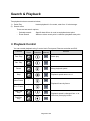
Playback Control
You can control playback using 3 control tools Front panel, Remote controller and GUI.
Function
Front
Panel
Remote
Controller
GUI
(Mouse)
Fwd. Play
Remark
Quick play
Rev. Play
Pause
Keep playback speed.
Stop
Next Frame
Playback speed returns to x1.
Playback frame by frame.
Prev. Frame
-
Fast Fwd.
Play
Playback speed is changed from x1 to
x64 when press play button.
Fast Rev.
Play
Page 26 of 69
1.
Front panel
Rev. Play
Fast Rev. Play
Stop
Fwd. Play
Fast Fwd. Play
Play / Pause
2.
Remote Controller
Play /Pause
Rev. Play
Fast Rev. Play
Fwd. Play
Fast Fwd. Play
Prev. Frame
Next Frame
Stop
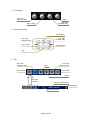
3. GUI
Rev. Play
Fast Rev. Play
Fwd. Play
Fast Fwd. Play
Stop
Next Frame
Prev. Frame
Pause
Playback
Controls
Recording date & time
Quit playback
Recording speed
Page 27 of 69
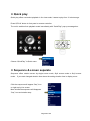
Quick play
Quick play offers convenient playback in live view mode, it starts to play from 10 minutes ago.
Press Q-PLAY button in front panel or remote controller.
The unit is switched into playback mode immediately with “QuickPlay” pop-up message box.
Choose “QuickPlay” in Quick menu.
Sequence & screen separate
Sequence offers rotation screen by single screen mode, 2by2 screen mode or 3by3 screen
mode. If you want changed duration time where the setting duration time in display menu.
Click the sequence will appear “Seq” icon
on right top by live screen.
More clicked the sequence will disappear
“Seq” icon and rotation stop.
Page 28 of 69
OSD On/Off
OSD Off offers the onscreen OSD is all disappear.
Then OSD Off item changed OSD on.
When you click the OSD On the OSD is appear.
Deinterlace On/Off
Deinterlace Off offers the Deinterlace mode off.
Then Deinterlace Off item changed Deinterlace On.
When you click the “Deinterlace On” the Deinterlace
mode on.
- Blank -
Page 29 of 69
Entering to search menu
1.
Front panel & Remote controller
Press SEARCH button in front panel or remote controller, then a menu panel will be shown.
2. GUI (Mouse)
Click Search icon in the status bar.
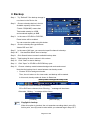
Calendar Search
Calendar search mode is a default mode.
If you are in Event mode, then choose “Calendar”
tab to switch to Calendar mode.
Step 1.
Choosing a date
You can choose one of red colored date.
Black colored date has no recording data.
Step 2.
Choosing a hour
Recording map will be shown in a hour unit.
The color on the map is indicating recording
mode as below.
▪ Red
: Normal Recording
▪ Blue
: Motion event
Page 30 of 69
▪ Yellow
: Alarm in event
▪ Green
: Two events at same time - Alarm in event & Motion event
You can start to playback by pressing “Start” button or back to step 1. By pressing
“Back”.
Step 3.
For choosing a minute, press “OK” in the recording map.
Choosing a minute & Play
Recording map will be shown in a minute unit.
You can start to playback by pressing “Start”
button or back to step 1. By pressing “Back”.
Pressing “OK” in the recording map also start
to play.
Step 4.
Playback Control & Return to search menu
▪
See “Playback Control” section above for playback control.
▪
Return to search menu
There are two ways to return to search menu from playback mode.
TIP
1)
Press “ESC” in front panel or remote controller
2)
Click
icon on playback control bar to quit playback mode.
Daylight in calendar search mode
Please, read “Daylight Saving Time(DST)” section first.
Daylight button will be shown if the selected date is including zone (A) and (B).
This button is useful when addressing start point in Zone(B).
The recording map will be updated when you press Daylight button.
Select Zone (B)
Page 31 of 69
Event Search
1
Step 1.
Select “Event” if you are in Calendar mode.
Step 2.
Select desired channel to search.
Step 3.
Set start date & time to search.
Step 4.
Set stop date & time to search.
Step 5.
Check event type to search.
Step 6.
Click Search, then event list will be shown.
Step 7.
Choose a one of event you want to play.
TIP
2
Tip
2
6
4
3
5
7
Daylight in event search mode
When this option is checked, searches range is limited to zone (B).
At this point, zone (B) must be exist within you selected rage in Step 6 & 7.
- Blank -
Page 32 of 69
Backup
You can backup recording data to USB storages or built-in optical storage.
Backup device
▪
Built-in CD/DVD (option)
▪
USB Flash / HDD / CD / DVD (Support USB 2.0 devices only.)
Backup file type
▪
Native DB(Database)
This type is an unique format for video recording.
You can play this format using Backup viewer only.
Native DB does not support individual channel backup.
▪
AVI
This type is a industrial standard AVI file.
Refer that some media player does not support H.264 AVI file.
It is recommended to use MPlayer for audio playback.
▬ MPlayer
: Visit http://www.mplayerhq.hu to download.
Try GOM player if you need other free player, but it does not support audio decoding.
▬ GOM Player
: Visit http://www.gomlab.com/eng/
to download.
It supports English, Chinese, Japanese and Korean.
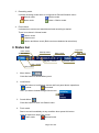
Entering to backup menu
Step 1.
Press Menu button, and select Storage menu.
Step 2.
Select Backup tab in Storage menu or select Backup in storage list menu.
Step 2.
Step 1.
Step 2.
Page 33 of 69
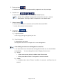
Backup
Step 1. Try “Refresh” if the backup storage is
2
not shown in the Device list.
Step 2.
1
Choose a backup device in the list.
5
Available capacity will be shown.
“Total:4.5 GB(8 MB)” means that
6
Total media catacity is 4.5GB,
7
and remained capacity is 8MB.
3
11
4
Tip
4
8
9
10
Step 3. In the case of CD-RW or DVD-RW,
12
Erase button will be enabled.
You can erase the media using this button.
Step 4.
Choose a backup file type between
“Native DB” and “AVI”.
Step 5. In the case of AVI type, you can select specific channel to backup.
Step 6 & 7.
Step 8.
Set start/End date & time to backup.
Click Search button to search available backup data.
Step 9. Total backup file size is shown in this column.
Step 10.
Click “Start” to start to backup.
Step 11.
Click “Open” to CD-RW or DVD-RW tray open.
Step 12.
Choose a backup mode between background mode and normal.
Note that the backup time is same between two backup mode.
▪
Choose YES for background mode.
Then, the unit eturns to live view mode, and backup will be started.
In this mode, backup status is shown in Status bar.
Backup status in background backup mode
▪
Choose NO to start to backup immediately.
CD or DVD were choosed, then “Burning…” message will be shown.
Otherwise, “Writing…” message will be shown.
[ CD/DVD ]
TIP
[ Other storage ]
Daylight in backup
When this option is checked, the unit searches recording data in zone (B).
At this point, zone (B) must be exist within you selected rage in Step 6 & 7.
Page 34 of 69
Chapter 4. Configuration
Press or click Menu button in front panel
or status bar to open menu panel.
Menu naming rule
TIP
For example, “Record :: Setup” is indicating
Setup menu in Record menu.
(Record menu is a root menu, and Setup menu is a sub-menu)
Summary
▪
Record
-
▪
Camera
-
▪
▪
Alarm In & Out settings / Email report settings / Buzzer settings
Display
-
Camera pane layout control / Status bar control
-
Spot output settings
Storage
-
▪
Camera naming / Audio on/Off / Color control
Event
-
▪
Image size settings / Frame rate settings / Schedule edit / Holiday settings
Storage view / Formatting / S.M.A.R.T. view / Writing settings / Backup
System
-
Network & Server settings
-
Log view & save to USB storage
-
User management
-
View DVR information : Remocon ID, F/W & Kernel version, MAC address
-
Gateway to Service menu
- Time synchronization
-
Email settings
Page 35 of 69
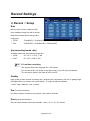
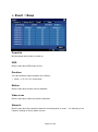
Record Settings
Record :: Setup
Size
Move to Size column, and press OK,
then available image size will be shown.
Note that all channels are using same
image size.
▪
NTSC
: 704x480(D1) / 704x240(HD1) / 352x240(CIF)
▪
PAL
: 704x576(D1) / 704x288(HD1) / 352x288(CIF)
fps (recording frame rate)
Available frame rate are listed by image size.
▪
NTSC
: 30 / 15 / 7.5 / 3.75 / 1.88
▪
PALT
: 25 / 12.5 / 6.25 / 3.125
TIP
D1 real time recording
The system which sees supports D1 / 120 frames
You can record D1 size image in real time frame, if you do using 4 channels.
This concept is same in the case of HD1 and CIF.
Quality
High quality means shorter recording time, because the compression file size is getting biger
and biger when you choose more good qiality.
5 quality levels are available.
▪ Best / High / Medium / Low / Lowest
Pre (Pre alarm duration)
Pre alarm duration is fixed as two options : None and 5 seconds.
Post (post alarm duration)
Six post alarm duration times are available : None / 3 / 5 / 10 / 20 / 30 sec
Page 36 of 69
Record :: Network
Size
Image size is dependent on
the record size
▪
NTSC
: 704x480(D1) / 704x240(HD1) / 352x240(CIF)
▪
PAL
: 704x576(D1) / 704x288(HD1) / 352x288(CIF)
Fps (network transmission frame rate)
Available network transmission frame rate are listed by image size.
▪
NTSC
: 30 / 15 / 7.5 / 3.75 / 1.88
▪
PALT
: 25 / 12.5 / 6.25 / 3.125
Quality
High quality means shorter recording time, because the compression file size is getting biger
and biger when you choose more good qiality.
5 quality levels are available.
▪ Best / High / Medium / Low / Lowest
- Blank -
Page 37 of 69
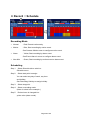
Record :: Schedule
1
4
5
2
3
Recording Mode
▪
Normal
: Red, Record continuously.
▪
Motion
: Blue, Start recording by motion event.
See Camera::Motion menu to configure motion event.
▪
Alarm
: Yellow, Start recording by alarm event.
See Event::Alarm In menu to configure alarm event.
▪
Alm+Mot
: Green, Start recording by motion event or alarm event.
Scheduling
Step 1.
Select Schedule tab to switch to
Schedule menu.
Step 2.
Select start point to assign.
You can select any day of week, any hour
and holiday.
See Recording::Holiday to assign holiday.
Step 3.
Select stop point.
Step 4.
Select a recording mode.
(Alarm is select in the example.)
Step 5.
Desired zone is changed into
yellow color (alarm mode).
Page 38 of 69
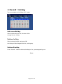
Record :: Holiday
You can assign your holidays for 2 years.
Add a new holiday
Select a date and press OK, the date will be
change into red, holiday.
Delete a holiday
Select a desired holiday and press OK,
the holiday will be changed into black, working day.
Delete all holiday
Press “Clear All” button to delete all holidays of two years assigned by user.
- Blank -
Page 39 of 69
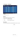
Camera Settings
Camera :: Setup
Name
You can change the camera name using
virtual keyboard.
Press OK to show virtual keyboard.
Enable
Enable or disabling the channel.
Note that Ch. 1 should be turned on always.
Audio
Check this option if you attach a microphone to the channel.
Sat / Con / Bri
You can adjust color settings using this menu.
Page 40 of 69
Camera :: Motion
Enable
It enables motion event.
Region
Motion detection cells are consist of 15x15 cells.
You can enable or disable each cells.
▪
Full
: All cells are enabled.
▪
User
: You can configure each cells.
Sensitivity
Five levels of motion detection sensitivity available, from step 1 to step 5.
- Blank -
Page 41 of 69
Camera :: PTZ
ID
It is a RS-485 device address.
You must set a address if PTZ camera is attached.
Available range is from 1 to 255.
You can change the PTZ camera ID using virtual keyboard.
Press OK to show virtual keyboard.
Model
You can choose a PTZ camera model or protocols.
Settings
You can configure RS-485 communication settings.
[ Settings ]
- Blank -
Page 42 of 69
Camera :: Keyboard
Model
You can choose a keyboard model when you connected by keyboard.
Settings
You can configure RS-485 communication settings.
- Blank -
Page 43 of 69
Event Settings
Event :: Alarm In
Type
You can configure a alarm device‟s output polarity.
▪
N/C : Normal Close
▪
N/O : Normal Open
Link Camera
The linked camera starts to recording when alarm in event is detected.
- Blank -
Page 44 of 69
Event :: Alarm Out
Alarm Out No
Set the alarm out no. you want to configure.
Duration
You can set alarm output durations up to 30 sec..
▪
None / 3 / 5 / 10 / 20 / 30 seconds
Motion
Alarm output will be turned on when motion event is detected.
Video Loss
Alarm output will be turned on when video loss event is detected.
Alarm In
Alarm output will be turned on when the camera is started to record by alarm in event. It is
reflecting “Link Camera” settings in Event::Alarm In menu.
For example,
▪
▪
Settings
-
Camera-1 is linked to Alarm In #1 and Alarm In #2 in Event::Alarm In menu.
-
Alarm In of Camera-1 is checked in Event::Alarm Out menu.
Action
Alarm out is turned on when Alarm #1 or(and) Alarm #2 event is activated.
Page 45 of 69
Event :: Email
Configure email settings in System::Email menu to use this service.
PowerUp
Email is sent when power is turned on.
HDD
Email is sent when HDD event occurs.
Motion
Email is sent when motion event is detected.
Video Loss
Email is sent when video loss event is detected.
Alarm In
Email is sent when the camera is started to record by alarm in event. It is reflecting “Link
Camera” settings in Event::Alarm in menu.
Page 46 of 69
Event :: Beep
PowerUp
Buzzer beeps when power is turned on.
HDD
Email is sent when HDD event occurs.
Duration
You can set alarm output durations up to 30 sec..
▪
None / 3 / 5 / 10 / 20 / 30 seconds
Motion
Email is sent when motion event is detected.
Video Loss
Email is sent when video loss event is detected.
Alarm In
Email is sent when the camera is started to record by alarm in event. It is reflecting “Link
Camera” settings in Event::Alarm in menu.
Page 47 of 69
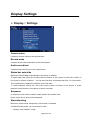
Display Settings
Display :: Settings
Camera name
It shows a camera name on the camera pane.
Record mode
It shows record mode and status on the camera pane.
Audio record icon
It shows audio record icon on the camera pane.
Status bar auto-hide
Status bar will be hidden automatically if this option is enabled.
To watch status bar, Move the mouse pointer to bottom of the screen or press OK or Menu in
front panel or remote controller. You can set show-time of the status bar from 1 to 10 seconds.
This configuration is applied to playback control bar also.
To watch playback control bar, move the mouse pointer to bottom of the screen or press
playback control button in front panel or remote controller.
Sequence
In check item main screen rotation enable and the set duration time.
Press combo box to show virtual keyboard.
Alpha blending
Menu box will be similar transparency if this option is enabled.
In Alpha blending mode, you can choose a value
▪
Opaque/ Low / Medium / High.
Page 48 of 69
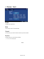
Display :: Spot
Enable
It enables spot operations.
Mode
There are two mode, Fixed and Rotate.
Channel
In Fixed mode, you need to choose a channel you want to watch.
Duration
In Rotate mode, you can choose a duration.
▪
3 / 5/ 10 / 20 / 30 seconds.
- Blank -
Page 49 of 69
Storage Settings
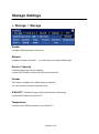
Storage :: Storage
Temperature Limit
HDD event occurs when HDD temperature exceed
This limit.
Enable
It enables HDD temperature limit event.
Refresh
It updates storage information. It is useful when you attach USB storage.
Device / Capacity
It shows storage types and its capacity.
Internal SATA storage is shown as SATA-{number} device.
Format
This button is enabled when USB storage is attached.
You can format the storage using this button.
S.M.A.R.T. (Self Monitoring Analysis and Reporting Technology)
It shows HDD health using S.M.A.R.T. .
Temperature
It shows current HDD temperature using S.M.A.R.T. .
Page 50 of 69
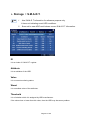
Storage :: S.M.A.R.T.
TIP
1.
Use S.M.A.R.T information for reference purpose only.
It does not indicating exact HDD conditions.
2.
Some old or new HDD could shows correct S.M.A.R.T. information.
Device
It shows the storage information.
ID
It is an index of S.M.A.R.T. register.
Attribute
It is an attribute of the HDD.
Value
It is a current monitoring status.
Worst
It is a smallest value of the attributes.
Threshold
It is a limitation which it is assigned by HDD manufacturer.
If the value close or lower than this value, then the HDD may has some problem.
Page 51 of 69
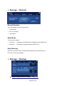
Storage :: Record
Record Duration
You can configure record time as below;
▪
Continuously
▪
30 / 60 / 90 days
▪
User Define
Write Mode
There are two modes;
▪
Overwrite
: Old data on the HDD will be erased when the HDD is full.
▪
Suspend
: Recording is stopped when the HDD is full.
Early Warning
HDD event will be issued if remained HDD capacity is less than this limit.
From 5% to 30% are available.
Storage :: Backup
Refer to “Backup” section in Chapter 3. Operation.
Page 52 of 69
System Settings
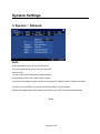
System :: Network
DHCP
Check this option if you do not using fixed IP.
The unit request an IP as soon as you save and
exit the menu.
You can verify the IP address and other network
configurations in this menu after a few minutes.
If the network condition is good, then the unit can get IP address within couple of seconds.
If you do not using DHCP, you have to fill all information out by yourself.
Please, ask details about the network information to your ISP or network administrator.
- Blank -
Page 53 of 69
System :: DDNS
DDNS
Check this option to enable Dynamic DNS function,
you can choose one of two DDNS.
1)
DNIP.NET
: Public DDNS (Registration is required.)
2)
MY-DDNS.COM
: Closed DDNS (Registration is not required, Exclusive for this DVR)
MY-DDNS.COM
This exclusive DDNS is very easy to use. Just assign a domain name and apply it.
Step 1)
Check DDNS option box.
Step 2)
Choose MY-DDNS.COM
Step 3)
Enter a name in Domain[my-ddns.com] column.
Step 4)
Click Apply button, then a success message box will be shown.
1
2
3
4
Page 54 of 69
DYNDNS
This DDNS is a public DDNS, and registration is essential.
Step 1)
Registration(sign-up) on the web.
Currently, we support DNIP.NET free service.
You need to sign-up at www.dyndns.com to get an ID and password.
Refer that you need to configure “port forwarding” if you are using a router.
Visit http://www.dyndns.com/ for details.
[ DYNDNS sign-up screen ]
Step 2)
Check DDNS option box.
Step 3)
Choose DYNDNS
Step 4)
Enter an ID and password that you registered at www.dyndns.com
Step 5)
Click Apply button, then a success message box will be shown.
2
3
4
4
5
Page 55 of 69
System :: Server
Network settings of the unit are shown in this menu.
TCP / UDP / HTTP port
These port is fixed to 5000, 5100 and 8080,
it is used for CMS and Web viewer service.
Max. Connect
This value is a limit of total number of network connections for live viewing.
System could be unstable if the connection is too much.
Max. Search
This value is a limit of total number of network connections for search.
Since search requires too much system resource, it could be a cause of unstable operation.
Event Server
Press “Event server” button appear server list box.
The server list is received server from event data by CMS host.
Page 56 of 69
System :: Log
You can verify history of the system operation in this log menu.
Type
You can choose a type of history such as System,
Setup, Search and etc…
Start / End
You can set search range using this column.
Search
Start to search log as soon as press Search button.
Save
You can save the log data using USB storage. File name is fixed to “log.txt”.
System :: User
Refer to “User management” section in Chapter 2. Pre-acknowledgement.
Page 57 of 69
System :: Info
Name
Name on network (CMS).
Remocon ID
Identification for IR remote controller.
See “Infrared remote controller” in
Chapter 2. Pre-acknowledgement.
Firmware Version
Firmware version information.
Kernel Version
Kernel version information.
MAC address
Identification of the unit on network, it must be unique to prevent conflict on the network.
Service Menu
You can switch to Service Menu through this button.
See Chapter 5. Service menu for details.
Page 58 of 69
System :: Email
Email-1 (Receive)
Primary receiver‟s email address.
Email-2 (Receive)
Secondary receiver‟s email address.
SMTP Auth
Use to SMTP Authentication.
Server
IP address or URL of SMTP server for sending.
ID
Sender email account of the SMTP server.
Passowrd
Password of the sender account.
TestSend
Test Mail will be sent as soon as press the button.
Page 59 of 69
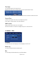
System :: Time Sync.
Time Sync.
When checked, the unit starts to synchronize
system clock with network time server using NTP.
NTP serevr offers most reliable atomic clock.
NTP Server
The unit will look for near network time server if you use “pool.ntp.org” .
You can use other network time server if the default server setting has some problem.
Port(UDP)
It is a NTP port fixed by network time server.
Period(Hour)
The unit synchronize the clock periodically, you can set its period in hour unit.
Server Time
It shows the time offered by network time server when press Get button.
Get
The unit try to get a time from network time server.
Server Time will be updated if there is no problem.
Apply
Change current system time using network time server, this is “Time Synchronization”.
TIP
Failure of time synchronization
If time difference is too big, then it shows failure message.
In this case, you need to try Time Sync. In Service::DateTime menu.
If system time is faster than network time server‟s time, then it is recommended to
backup recent data. Otherwise, it will be erased.
Page 60 of 69
System :: Etc
Key Beep
Buzzer beeps when front panel button or
remote controller button is pressed.
Temperature Unit
You can choose temperature display unit between celsius degree and fahrenheit degree.
Auto-Logout
It enables auto-logout operations.
In auto-logout operations, you can adjust a duration using virtual keyboard.
It‟s duration adjustable to one to sixty minute by one minute unit.
VideoMode
You can choose video mode between NTSC and PAL.
If you change the video mode, a warning window appears
VideoLoss Record
If you enable this item to record the video loss.
Page 61 of 69
Chapter 5. Admin Menu
Enterin to service menu
You can enter to service menu through System::Info menu.
Step 2.
Step 1.
Step 3.
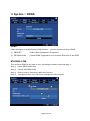
Admin :: Upgrade
1
2
3
You can upgrade kernel and firmware using
USB storage at same time or separately.
Step 1.
Choose USB storage which is containing
Upgrade file.
Press “Refresh” button
if there is no USB storage device.
Step 2.
Press “Refresh” button.
The unit will start to scan USB storage, and show its version.
Step 3.
Press “Upgrade” button to start to upgrade.
Upgrade will takes a couple of minutes.
Page 62 of 69
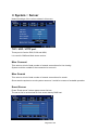
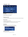
Admin :: Config
You can export or import unit‟s configuration
using USB storage.
▪
Factory default : Return to factory default settings.
▪
Export
: Copy this unit‟s configuration file to USB storage.
You can find “Config.dat” in the USB storage.
▪
Import
: Copy configuration file from USB storage.
Admin :: Format
Since recording is stopped in Service menu, you can format any data disk.
Press Format button on the GUI.
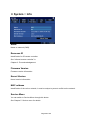
Admin :: DateTime
Page 63 of 69
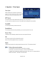
Time Sync.
You can adjust system clock using this menu.
Standard time will be shown as below when you press “Synchronization” button.
Press “Sync.” To adjust system clock to standard time which is read from network time server.
Current Time
It shows current system clock, and you can adjust it by manual.
Press “Apply” to change system clock after adjustment.
GMT/Location
Assign correct location where the unit is installed.
Since this information is a reference of daylight saving rule, it must be correct.
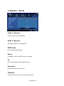
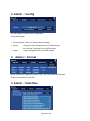
Admin :: Etc
Language
You can choose your local language or other language you want to use.
Delete Log
You can click a delete button then delete log file.
Mac
You can change the Mac address then you get Mac address.
Page 64 of 69
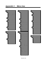
Appendix 1.
Menu tree
Record
Camera
Setup
Setup
Event
Alarm In
Image Size
Camera Name
Type
Fps (Recording Speed)
Camera Enable
Linked Camera
Image Quality
Audio Enable
Pre Alarm
Saturation
Alarm Out No
Post Alarm
Contrast
Duration
Bright
Motion
Network
Fps (Network speed)
Image Quality
Schedule
None
Normal
Motion
Enable
Region
Sensitivity
PTZ
Alarm Out
Video Loss
Alarm In
Email
Power Up
HDD
Motion
ID
Motion
Alarm
Model
Video Loss
Alarm+Motion
Holiday
Setting
Keyboard
Alarm In
Beep
Today
Keyboard Model
Power Up
Clear All
Setting
HDD
DVR Number
Duration
Display
Screen
Storage
Storage
Motion
Video Loss
Alarm In
Camera Name
Device
Record Mode
Capacity
Audio Record Icon
Type
Status bar auto-hide
Format
Status bar show time
S.M.A.R.T. Health
Address
Temperature
ID
Spot
Storage
FTP
Enable
S.M.A.R.T.
Password
Mode
Record
Port
Channel
Record Duration
Duration
Write Mode
Early warning enable
Early warning level(%)
Backup
Device
Capacity
Channel
Type
Daylight Saving
Start
End
Data Size
[ Continue ]
Page 65 of 69
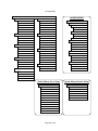
Schedule
[ Continued ]
System
Network
ADMIN MENU
Info
Admin
DHCP Enable
DVR Name
IP Address
Remocon ID
Subnet
Firmware Version
Gateway
Kernel Version
DNS1
MAC Address
F/W Version
DNS2
Service Menu
Current Version
DDNS
Upgrade
Device
Kernel Version
Kernel Version
Time Sync.
F/W Version
Enable
NTP Server
Server
Port
ID
Period(Hour)
Password
Server Time
Device
Get
Factory Default
Apply
Export
Server
TCP Port
UDP Port
Upgrade
Config
Email
Import
HTTP Port
Email#1
Format
Max. Connection
Email#2
DateTime
Max. Search
SMTP Server
Time Sync.
SMTP ID
Current Time
SMTP Password
GMT / Location
Log
Type
Test Send
Start / End
Search
Save
User
Etc
Languag
Etc
Key Beep
Delete Log
Temp. Unit („C/‟F)
Get Mac Address
ID
Password
Permission
Hidden
Quick Menu (Live View)
Quick Menu
Quick Menu(Search View)
Quick Menu
Zoom
Volume
PTZ
OSD on
Quick Play
Deinterlace on
Lock
2x2
Volume
3x3
Sequence
4x4
OSD on
Deinterlace on
2x2
3x3
4x4
Shutdown
Page 66 of 69
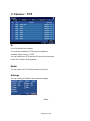
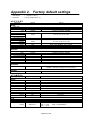
Appendix 2.
Factory default settings
*
F/W Version
:
1.1.2 [ MAY 7, 2010 ]
*
Password
:
11111111 (Eight digit of „1‟)
■RECORD
Parameter
Default
Range
352x240
352x288
704x480 / 704x240 / 352x240
704x576 / 704x288 / 352x288
30 fps
30 / 15 / 7.5 / 3.75 / 1.88
25 fps
25 / 12.5 / 6.25 / 3.13 / 1.56
Best
5 sec
5 sec
Best / High / Medium / Low / Lowest
None / 5 sec.
None / 3 / 5 / 10 / 20 / 30 sec.
352x240
352x288
704x480 / 704x240 / 352x240
704x576 / 704x288 / 352x288
30 fps
30 / 15 / 7.5 / 3.75 / 1.88
25 fps
Best
25 / 12.5 / 6.25 / 3.13 / 1.56
Best / High / Medium / Low / Lowest
Normal
None / Normal / Alarm / Motion / Alm+Mot
(Default = Normal recording for 24 hours/7days)
-
No Holiday
Setup
Image Size
NTSC
PAL
Frame Rate (NTSC)
704x480
704x240
352x240
Frame Rate (PAL)
704x576
704x288
352x288
Quality
Pre-Alarm
Post-Alarm
Network
Image Size
NTSC
PAL
Frame Rate (NTSC)
352x240
Frame Rate (PAL)
352x288
Quality
Schedule
Mode
Holiday
Settings
■CAME RA
Parameter
Default
Range
Name
Enable
Audio
Saturation
Contrast
Brightness
“CAMnn”
Checked
Unchecked
58
44
50
Max. 12 character
Checked / Unchecked
Checked / Unchecked
0 ~ 100
0 ~ 100
0 ~ 100
Enable
Region
Sensitivity
Checked
Full
Step 1 (Hi)
Checked / Unchecked
Full / User
Step 1 (Hi) ~ Step 5 (Lo)
ID
Model
001 ~ 255
None
Setting
9600 8-N-1
001 ~ 255
Various
Baud : 1200 / 2400 / 4800 / 9600 / 19200 bps
Data : 7 / 8 bit,
Parity : None/Odd/Even
Stop : 1 / 2 bit
Setup
Motion
PTZ
Page 67 of 69
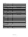
■EVENT
Parameter
Default
Range
N/C
1:1
N/C or N/O
1 ~ 16
Duration
Motion
Video Loss
Alarm In
5 sec
Unchecked
Unchecked
Unchecked
None / 3 / 5 / 10 / 20 / 30sec
Checked / Unchecked
Checked / Unchecked
Checked / Unchecked
Power Up
HDD
Motion
Video Loss
Alarm In
Unchecked
Unchecked
Unchecked
Unchecked
Unchecked
Checked / Unchecked
Checked / Unchecked
Checked / Unchecked
Checked / Unchecked
Checked / Unchecked
Duration
Power Up
HDD
Motion
Video Loss
Alarm In
5 sec
Unchecked
Unchecked
Unchecked
Unchecked
Unchecked
None / 3 / 5 / 10 / 20 / 30sec
Checked / Unchecked
Checked / Unchecked
Checked / Unchecked
Checked / Unchecked
Checked / Unchecked
Default
Range
Checked
Checked
Checked
Unchecked
None
Unchecked
Medium
Checked / Unchecked
Checked / Unchecked
Checked / Unchecked
Checked / Unchecked
1 / 3 / 5 / 10 sec
Checked / Unchecked
Opaque / Low / Medium / High
Unchecked
Fixed
1
3 sec
Checked / Unchecked
Fixed / Rotate
1 ~ 16
3 / 5 / 10 / 20 / 30
Alarm In
Type
Link Camera
Alarm Out
Email
Beep
■ D I S P LAY
Parameter
Screen
Camera name
Record mode
Audio record icon
Status bar autohide
Show
Alpha Blending
Show
Spot
Enable
Mode
Channel
Duration
■STO RAG E
Parameter
Default
Range
Record
Record Duration
Write mode
Early Warning
Early Warning Level
Continuously
Overwrite
Checked
5%
Continuously / 30 / 60 / 90 Days / User define (1 ~ 365 Days)
Overwrite / Suspend
Checked / Unchecked
5 / 10 / 20 / 30% (Remained Capacity)
Page 68 of 69
■SYSTEM
Parameter
Default
Range
DHCP
IP
Subnet
Gateway
DNS1
DNS2
Unchecked
192.168.0.100
255.255.255.0
192.168.0.1
168.126.63.1
168.126.63.2
Checked / Unchecked
-
DDNS
Server
ID
Password
Domain
Unchecked
-
Checked / Unchecked
Max. 20 character
Max. 20 character
Max. 20 character
5000
5100
8080
6
1
0 ~ 65535
0 ~ 65535
0 ~ 65535
1 ~ 20 (TBD)
1 ~ 2 (TBD)
All
Live
Search
“11111111”
None
All
Max. 10 character, Live / Search / Setup / All
Max. 8 digit, Accept alphabet and number, Case sensitive
1~4
DVR
0
Max. 16 characters
0 ~ 99
-
Max. 30 characters
Max. 30 characters
-
Max. 25 characters
Max. 25 characters
Max. 40 characters
Time Sync.
NTP Server
Port(UDP)
Period
Unchecked
pool.ntp.org
123
3 Hour
Checked / Unchecked
Min. 25 character
1 ~ 65535
1 ~ 24 Hour
Key Beep
Temperature Unit
Auto-Logout
Period(Min)
VideoMode
VideoLoss Record
Checked
Celsius
Unchecked
5 Minute
NTSC
Unchecked
Checked / Unchecked
Celsius / Fahrenheit
Checked / Unchecked
5 ~ 60 Minute
NTSC / PAL
Checked / Unchecked
Network
DDNS
Server
TCP Port
UDP Port
HTTP Port
Max. Connect
Max. Search
User
Admin
Guest
User1 ~ User18
Password
Hidden Camera
Info
Name
Remocon ID
Email
Email-1(Receive)
Email-1(Receive)
SMTP (send)
Server
ID
Password
Time Sync.
Etc
- End of document -
Page 69 of 69