1
6
Before connecting any power to the Vortex board, the power link options must be setup correctly to
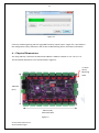
ensure safe and proper power operation. There are two main power configuration links L1 and L2 on
the board, as shown below. L2 selects where the 5V VCC logic power for all the on board logic ICs is
derived from. There are three main jumper configurations and these are marked on the PCB as ‘A’,
‘B’ and ‘C’. The three configurations are as follows:
Configuration A:
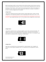
Logic power is derived directly from either the bank 1 or bank 2 power input. In order to use this
configuration, the voltage being supplied to the corresponding power bank must be 5V DC +-10%.
Exceeding 5V or reversing polarity for the VCC logic will destroy the on-board logic ICs as there is no
protection. The L2 jumper should be in the ‘A’ or 1-2 position for this configuration as shown below:
A
B
C
Figure1
Configuration B:
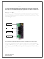
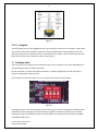
Logic power is derived from the on board 5V regulator via one of the two main power banks. The
regulator can accept any input voltage between 6V and 30V DC. This option is best used when
powering either of the main power banks with a voltage greater than 5V DC. The L2 jumper should
be in the ‘B’ or 3-4 position for this configuration as shown below:
A
B
C
Figure 2
Configuration C:
Logic power is derived from the on board regulator by a separate power source altogether via
connector J4. The L2 jumper should be in the ‘C’ or 5-6 position for this configuration as shown
below:
A
Vortex 16 User Manual V1.2
© 2013 Advatek Lights
B
C