1
ISSN 1744-1986
Technical Report N
O
2011/ 09
blinkit: Maintaining Invariant Traceability
through Bidirectional Transformations - A
Technical Report
Yijun Yu and Yu Lin and Zhenjiang Hu and Soichiro Hidaka and
Hiroyuki Kato and Lionel Montrieux
29 September, 2011
Department of Computing
Faculty of Mathematics, Computing and Technology
The Open University
Walton Hall, Milton Keynes, MK7 6AA
United Kingdom
http://computing.open.ac.uk
blinkit: Maintaining Invariant Traceability
through Bidirectional Transformations – A
Technical Report
Yijun Yu1 , Yu Lin2 , Zhenjiang Hu3 , Soichiro Hidaka3 , Hiroyuki Kato3 , Lionel Montrieux1
1
2
Department of Computing, The Open University, Milton Keynes, United Kingdom
Department of Computer Science, University of Illinois at Urbana-Champaign, USA
3
National Institute of Informatics, Tokyo, Japan
Abstract—Following the “convention over configuration”
paradigm, model-driven development (MDD) generates code to
implement the “default” behaviour that has been specified by
a template separate from the input model, reducing the effort
of decisions for developers. For flexibility, users of MDD are
allowed to customise the model and the generated code in parallel.
A synchronisation of changed model or code is maintained by
reflecting them on the other end of the code generation, as
long as the traceability is unchanged. However, such invariant
traceability between corresponding model and code elements can
be violated either when (a) users of MDD would protect custom
changes from the generated code, or when (b) developers of MDD
would change the template for generating the default behaviour.
A mismatch between user and template code is inevitable as
they evolve for their own purposes. In this paper, we propose
a two-layered invariant traceability framework that reduces the
number of mismatches through bidirectional transformations. On
top of existing vertical (model↔code) synchronizations between a
model and the template code, a horizontal (code↔code) synchronisation between user and template code is supported, aligning
the changes in both directions. Our blinkit tool is evaluated
using the dataset available from the CVS repositories of a MDD
project: Eclipse MDT/GMF.
I. I NTRODUCTION
Aiming at increasing productivity, “convention over configuration” is a software design paradigm to reduce the decisions for developers while preserving flexibility. Following
this paradigm, model-driven development (MDD) of software
projects (e.g., Eclipse Modeling Framework, EMF) generates
code from models to implement the “default” behaviour, which
was specified by a template separate from the input model.
As users of MDD, programmers are allowed to customise the
generated code, and the modelers are allowed to modify the
models further. To support the eventual round-trip synchronisation of model and code [1], markers for traceability correspondence (e.g., @generated) are inserted at the beginning of the
generated methods by MDD, indicating to the programmers
that all changes to the model and the template will be reflected
by the annotated method. In other words, any change made by
programmers on such methods will get lost after another round
of code generation. In order to protect such changes in the user
code from getting lost, programmers are allowed to modify the
@generated marker to @generated NOT, instructing the
code generators to skip the user-specified methods.
This technique is common in MDD practice, for another example, the Acceleo Model2Text project uses “[protected]
... [/protected]” annotations to enclose user-specified
parts for arbitrary textual outputs. To illustrate its problematic
use in Java development, we use EMF, the Eclipse Modeling
Framework (EMF) [2] as an exemplar MDD framework. Using
EMF, the template code is generated first, later refined manually into functioning user code. Once programmers change the
model and regenerate the template code, it brings the necessity
of the traceability to and from the user code.
Ideally, a round-trip engineering should be supported such
that modifications can be correctly propagated in both directions [3]. Current state-of-the-art tools of MDD such as EMF
maintain the synchronisation of changed model and code by
reflecting them on either side of code generation. However,
such invariant traceability links between corresponding model
and code elements can be easily violated either when (a) users
of MDD would protect custom changes from the generated
code by changing @generated to @generated NOT or
when (b) developers of MDD would change the template
for generating the default behaviour for those @generated
methods while all users’ change will be lost. In either case,
a better solution would be to preserve the changes made by
the users as well as the changes made on the model as long
as they are consistent. In Section III, a detailed example will
illustrate the problems such a mismatch can cause.
In this paper, we consider the mismatch problem between
user and template codes that is inevitable as they evolve
for their own purposes, and propose a two-layered invariant
traceability framework that reduces the number of mismatches
and merges the changes when possible through bidirectional
transformations: The first layer of the framework synchronises
the structural changes between the model and the template
code at the API level vertically (denoted by model↔code)
using existing state-of-the-art MDD tools such as EMF; the
second layer synchronises the behavioural changes between
the template code and the user code inside the method bodies
horizontally (denoted by code↔code) if users wish to preserve both types of changes. Aligning these changes in both
directions, our blinkit tool is evaluated using the dataset
available from the CVS repositories of the Eclipse MDD
projects EMF and GMF.
To effectively use the invariant traceability framework,
users only need to insert a traceability marker annotation
@generated INV, instructing the code generator to automatically (a) compare the differences between the current
template and user methods; and (b) derive a bidirectional
transformation for future code generation to reflect changes
of the model or changes of the template back to the users
methods. The tool gives warnings when there are inconsistencies between the template and the user code.
To verify our ideas, a prototype has been successfully
applied it to changes recorded in the evolution of the GMF
framework from its CVS repository, which shows that our
new approach of round-trip engineering is promising and
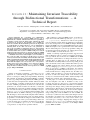
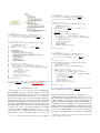
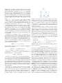
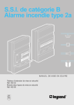
potentially useful in practice. Figure I presents an overview
of the blinkit framework when it is applied to the case
study of EMF/GMF, where EMF is the synchronisation framework for vertical traceability and blinkit is the horizontal
synchronisation counterpart.
The major technical contributions of the work can be
summarised as follows:
• From a user’s perspective, a new type of annotations
@generated INV is supported as explicit markers
for automatic maintenance of invariant traceability between template (@generated) and user (@generated
NOT) code;
• A novel algorithm is proposed for automatically generating a one-pass bidirectional transformation from the
meaningful differences between the template code and
arbitrarily modified user code such that the roundtrip
relation between the structures of the model and the code
can be correctly maintained.
• An empirical study is done on a CVS repository of the
state-of-the-art MDD project GMF, telling the benefits of
maintaining invariant traceability links, especially when
the 178 changes to the @model parts have impact on the
bodies of 54% of the 28,070 revisions of methods marked
by @generated NOT.
Comparing to existing MDD and traceability approaches,
blinkit derives invariant transformations automatically
from meaningful changes in the source code [4]. Unlike our
initial work that proposes to apply bidirectional transformations directly on class diagrams and Java code [5], this work
takes full advantages of the state-of-art synchronisations of
many-to-many vertical traceability links between the model
and the template code, such that the horizontal bidirectional
transformations are applied only to the method bodies relevant to the user-modified behaviours. Since the template and
the user method code are at the same level of abstraction,
blinkit is allowed to derive a forward transformation from
the user method to the generated method. There is no longer a
need, like [5], to monitor the execution logs of user-specified
ATL transformations.
The remainder of this paper is organised as follows: Section II gives some preliminary knowledge on EMF framework
and introduces the bidirectional transformation mechanism
implemented by the blinkit tool. Section III provides one
Fig. 1. An overview of the horizontal and vertical traceability links in the
bidirectional invariant traceability framework: blink. V1 and V2 are two
revisions of model, template or user codes extracted from the CVS repository
of a software development project using EMF code generation.
motivation example to illustrate the synchronisation problem
of invariant traceability. Section IV gives an overview of
the roud-trip process for horizontal and vertical invariant
traceability and indicates the position of the blinkit tool
in the process. Section V describes the technical details of
the blinkit tool in terms of the bi-similarity properties, the
generation of bidirectional transformations from meaningful
changes, and the one-pass optimisation for improved efficiency
of the transformations. Section VI presents the observations
of the CVS evolution history of the GMF project to show the
number of cases where the @generated INV markers can
help. Section VII compares the related work and Section VIII
concludes the paper.
II. BACKGROUND
A. EMF as a state-of-the-art MDD framework
The Eclipse Modeling Framework (EMF) [2] is a MDD
framework and a code generation facility for building Eclipse
tools and other applications around a structured model. From
a metamodel specified in XMI or XML Schema [6], EMF
generates default (i.e., template) Eclipse plugin tools that
consist of Java classes for manipulating the model, along with
Java adapter classes for viewing and editing a model. From
a rather complex metamodel, it is impractical to generate all
source code because programmers may customise the default
behaviour by modifying some parts of the code in order to
achieve their own goals. Using EMF, the template code is
generated first, later refined manually into functioning user
code. Once programmers change the model and regenerate
the template code, it brings the necessity of the traceability to
and from the user code.
The MDD part of the EMF consists of one code generation component (i.e., JMerge) to generate source code
from a metamodel (i.e., .ecore). The template used by the
code generator is specified in the JavaJET template language
similar to that of JSP, which will concretise the template
variables with the default values specified in the corresponding
.genmodel configuration files. There is no one-to-one mapping
between a class operation to a Java method in this code
1
a b c
2
3
4
c
a a
5
d
6
Fig. 3.
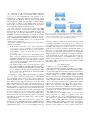
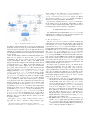
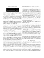
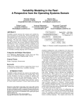
Fig. 2.
A simple rooted and edge-labelled graph
Architecture of the GRoundTram system
subgraph pointed by the edge labelled b from the root by
generation: A class in the class model can be implemented
in multiple classes in the model, impl, util, edit and
editor packages scattered across the generated model,
edit, editor, and test plugins. In addition, there will be
Package and Factory classes created and instantiated by
the classes in the model. Therefore, it is not easy to maintain
such many-to-many relationships using traditional traceability
links techniques.
Note that EMF will be used in this study both as a subject
matter (as part of the MDT case study), as well as a component
of our solution. Parts of the EMF tool were generated using the
EMF code generator as well. It can be seen from the existing
EMF implementation that developers marked some methods
as @generated NOT to preserve the changes that cannot be
generated from the Ecore models alone. It is therefore common
to say that code generated from EMF will be modified by users
in practice.
select $g where {b : $g} in $db,
delete the subgraph (rooted at node 5) reached by the path b.a
by
in $db,
delete b.a →
and insert a subgraph G under the node reached from the path
a.a by
extend a.a →
with G in $db.
III. A M OTIVATING E XAMPLE
To illustrate the problem concretely, we use a constructed
example here. Suppose a user of the EMF specifies initially
a simple model that consists of one Entity class with a
single name attribute. Using the code generation of EMF,
she will obtain a default implementation which consists of
8 compilation units in Java (Figure 4).
B. Bidirectional Transformation
We use GRoundTram [7] to do bidirectional transformation
for graphs. GRoundTram provides a well-behaved framework
for bidirectional model transformation that guarantees the
roundtrip property in bidirectional transformation. Figure 1
depicts an architecture of the GRoundTram system. A model
transformation is described in UnQL+ [8], an extension of the
SQL-like graph query language UnQL [9] with three graph
update constructs to achieve efficiency and expressiveness,
namely Replacing, Deleting, and Extending. The model transformation is then desugared to the core algebra (UnCal) which
consists of a set of constructors for building graphs and a
powerful structural recursion for manipulating graphs. This
graph algebra can have clear bidirectional semantics and be
efficiently evaluated in a bidirectional manner [10]. Graphs
(models) in UnQL+ are rooted and edge-labelled ones (i.e.
all information is stored as labels on edges rather than on
nodes and the labels on nodes have no particular meaning),
and represented in UnCAL or the standard Dot format which
can be visualised and edited by the popular Graphviz tool [11].
To have a concrete idea of UnQL+, consider a simple graph
$db (the root is the node 1) in Figure 3. We can select the
⇒
Fig. 4.
Default implementation code generated from the EMF metamodel
Figure 5 lists parts of the generated code. The Entity
Java interface has both getter and setter methods for the name
attribute. They are commented by @generated annotations
which indicate that the methods are part of the default implementation. Similarly, such @generated annotations are
added to every generated element in the code, e.g., shown in
the skeleton of EntityImpl Java class.
The annotation @generated defines a single-trip traceability contract from the model to the annotated code element.
A change in the model or a change in the modeling framework
1
2
3
4
5
6
7
package e x a m p l e ;
import o r g . e c l i p s e . emf . e c o r e . E O b j e c t ;
/ ∗ ∗ @model ∗ /
public i n t e r f a c e E n t i t y extends EObject {
/ ∗ ∗ @model ∗ / p u b l i c S t r i n g getName ( ) ;
/ ∗ ∗ @generated ∗ / v o i d setName ( S t r i n g v a l u e ) ;
}
1
2
3
4
5
package e x a m p l e . i m p l ;
import e x a m p l e . E n t i t y ;
...
/ ∗ ∗ @generated ∗ /
public c l a s s EntityImpl extends EObjectImpl
implements E n t i t y {
...
/ ∗ ∗ @generated ∗ /
p r o t e c t e d S t r i n g name = NAME EDEFAULT ;
...
/ ∗ ∗ @generated ∗ /
p u b l i c S t r i n g getName ( ) { r e t u r n name ; }
/ ∗ ∗ @generated ∗ /
p u b l i c v o i d setName ( S t r i n g newName ) { . . . }
...
/ ∗ ∗ @generated ∗ /
@Override
public String t o S t r i n g ( ) {
i f ( e I s P r o x y ( ) ) return super . t o S t r i n g ( ) ;
S t r i n g B u f f e r r e s u l t = new S t r i n g B u f f e r ( s u p e r .
toString () ) ;
r e s u l t . a p p e n d ( ” ( name : ” ) ;
r e s u l t . a p p e n d ( name ) ;
r e s u l t . append ( ’ ) ’ ) ;
return r e s u l t . t o S t r i n g ( ) ;
}
} / / EntityImpl
6
7
8
9
10
11
12
13
14
15
16
17
18
19
20
21
22
23
24
25
Fig. 5.
1
2
3
4
5
6
7
8
9
10
11
12
13
14
15
16
17
18
19
20
21
22
23
/ ∗ ∗ @model ∗ /
public i n t e r f a c e E n t i t y extends EObject {
/ ∗ ∗ @model ∗ / p u b l i c S t r i n g g e t NameID
() ;
:
/ ∗ ∗ @generated ∗ / p u b l i c v o i d setName ( ) ;
}
...
/ ∗ ∗ @generated ∗ /
public c l a s s EntityImpl extends EObjectImpl
implements E n t i t y {
/ ∗ ∗ @generated ∗ /
p u b l i c S t r i n g g e t Name::
ID ( ) { r e t u r n name ; }
...
/ ∗ ∗ @generated ::::
NOT ∗ /
@Override
p u b l i c S t r i n g t o S t r i n g ( ::::
String :::
type ) {
i f ( e I s P r o x y ( ) ) return super . t o S t r i n g ( ) ;
S t r i n g B u f f e r r e s u l t = new S t r i n g B u f f e r ( s u p e r .
toString () ) ;
r e s u l t . a p p e n d ( ” ( name : ” ) ;
r e s u l t . a p p e n d ( name ) ;
r e s u l t . append ( ’ ) ’ ) ;
result.append(type);
:::::::::::::
return r e s u l t . t o S t r i n g ( ) ;
}
} / / EntityImpl
⇓
Fig. 6. User’s modifications to the generated code: insertions are underlined
::::::
and the deletions are striked out; the changes are reflected to the model
Parts of the generated code in Fig. 4
can propagate to the genenerated code; however, a change on
these generated code will not cause a change to the reflected
model and will thus be discarded upon next code generation.
Because the default implementation is not always desired,
the code generation shall keep user specified changes as long
as they are not inside the range of generated traceability. This
can be achieved by adapting the @generatedannotation into
@generated NOT , a non-binding traceability that reflects
programmers’ intention that it will not be changed when
the implementation code is regenerated. Note that such nonbinding traceability indicated by @generated NOT is still
different from those without any annotation at all: Without
such an annotation, EMF will generate new implementation
of a method body following the templates.
However, this workaround is not ideal. Suppose a user
parameterises the toString method in order to append
an additional type to the returned result. To guard her
method from being overwritten by future code generations,
the annotation @generated NOT is used. She also applies
a Rename Method refactoring, changing the getName method
into getID. The modified parts are shown in Figure 6.
Propagating these changes back to the model, the name
attributed will be automatically renamed into iD, following
the naming convention that attributes start with lower case
identifiers.
The regeneration of the code will result in changes in
Figure 7: the setter methods and the implementations of both
getter/setter methods are modified according to the default implementation of the new model. These are expected. However,
two unexpected changes are not desirable. First, a compilation
error results from the change in the default implementation,
where the attribute name used in the user controlled code
no longer exists. Secondly, the default implementation of
toString method is generated with the original signature,
which will of course become dead code since the user has
already modified all call sites of toString to reflect the
insertion of new type. Similarly, the user specified toString
method can also become dead code, if it is no longer invoked
by the new default implementation.
Compilation errors are relatively easy to spot by the programmer with the aid of Eclipse IDE, the dead code problems
are more subtle and more difficult for developers to be aware
of the consequences.
Ideally, the user is in full control: she can specify which
parts of the code are in the traceability contract so that the
default implementation is kept, and which parts of the code
are not in the traceability contract so that her changes there
will not be overwritten. For this purpose, a new annotation
for invariant traceability (@generated INV) will be used
in our proposed approach. As a result, Figure 8 illustrates the
changes to be propagated to users’ code after our approach of
bidirectional transformation is adopted.
⇒
1
2
3
4
5
6
7
8
9
10
11
12
13
14
15
16
17
18
19
20
21
22
23
24
25
26
27
28
29
30
31
⇒
/ ∗ ∗ @model ∗ /
public i n t e r f a c e E n t i t y extends EObject {
/ ∗ ∗ @model ∗ / p u b l i c S t r i n g g e t I D ( ) ;
/ ∗ ∗ @generated ∗ / p u b l i c v o i d s e t Name::
ID ( ) ;
}
...
/ ∗ ∗ @generated ∗ /
public c l a s s EntityImpl extends EObjectImpl
implements E n t i t y {
/ ∗ ∗ @generated ∗ /
p u b l i c S t r i n g g e t I D ( ) { r e t u r n name::
iD ; }
...
/**@generated*/
::::::::::
public
String toString() {
:::::::::::::::::
if
(eIsProxy()) return super.toString();
:::::::::::::::::::::::::
StringBuffer
result = new StringBuffer(super.toString());
:::::::::::::::::::::::::::::::::::::
result.append(”
(iD: ”);
:::::::::::::::
result.append(iD);
::::::::::::
result.append(’)’);
::::::::::::
return
result.toString();
:::::::::::::::
}:
/ ∗ ∗ @generated NOT ∗ /
public String t o S t r i n g ( String type ) {
i f ( e I s P r o x y ( ) ) return super . t o S t r i n g ( ) ;
S t r i n g B u f f e r r e s u l t = new S t r i n g B u f f e r ( s u p e r .
toString () ) ;
r e s u l t . a p p e n d ( ” ( name : ” ) ;
r e s u l t . a p p e n d ( name ) ;
r e s u l t . append ( ’ ) ’ ) ;
r e s u l t . append ( t y p e ) ;
return r e s u l t . t o S t r i n g ( ) ;
}
} / / EntityImpl
Fig. 7. Regenerated code from the model: insertions are :::::::
underlined and the
deletions are striked out, compilation error is double underlined.
IV. OVERVIEW OF blinkit
The prototype blinkit∗ supports our idea of maintaining
the traceability of the user code and template code through
bidirectional transformation. Figure 9 gives an overview of
the dataflow of the components inside blinkit. The solid
arrows represent three types of operations made by developers
while the open- and close-ended dash arrows represent forward
and backward transformations, respectively. First, developers
define an original EMF model and generate template code
from EMF engine ().
1 Developers may modify the template
code into user code to meet their requirements and mark
some parts of their code with annotation @generated INV
().
2 Developers can change the model if needed ()
3 and
regenerate the code ().
1 Note that, without blinkit, step
∗ blinkit
can be downloaded from website http://sead1.open.ac.uk/linkit/
1
2
3
4
5
6
7
8
9
10
11
12
13
14
15
16
17
18
19
20
21
22
23
/ ∗ ∗ @model ∗ /
public i n t e r f a c e E n t i t y extends EObject {
/ ∗ ∗ @model ∗ / p u b l i c S t r i n g g e t NameID
() ;
:
/ ∗ ∗ @generated ∗ / p u b l i c v o i d setName ( ) ;
}
...
/ ∗ ∗ @generated ∗ /
public c l a s s EntityImpl extends EObjectImpl
implements E n t i t y {
/ ∗ ∗ @generated ∗ /
p u b l i c S t r i n g g e t Name::
ID ( ) { r e t u r n name ; }
...
/ ∗ ∗ @generated :::
INV ∗ /
@Override
p u b l i c S t r i n g t o S t r i n g ( ::::
String :::
type ) {
i f ( e I s P r o x y ( ) ) return super . t o S t r i n g ( ) ;
S t r i n g B u f f e r r e s u l t = new S t r i n g B u f f e r ( s u p e r .
toString () ) ;
r e s u l t . a p p e n d ( ” ( name : ” ) ;
r e s u l t . a p p e n d ( name ) ;
r e s u l t . append ( ’ ) ’ ) ;
result.append(type);
:::::::::::::
return r e s u l t . t o S t r i n g ( ) ;
}
} / / EntityImpl
⇓
1
2
3
4
5
6
7
8
9
10
11
12
13
14
15
16
17
18
19
20
21
22
/ ∗ ∗ @model ∗ /
public i n t e r f a c e E n t i t y extends EObject {
/ ∗ ∗ @model ∗ / p u b l i c S t r i n g g e t I D ( ) ;
/ ∗ ∗ @generated ∗ / p u b l i c v o i d s e t Name::
ID ( ) ;
}
...
/ ∗ ∗ @generated ∗ /
public c l a s s EntityImpl extends EObjectImpl
implements E n t i t y {
/ ∗ ∗ @generated ∗ /
p u b l i c S t r i n g g e t I D ( ) { r e t u r n name::
iD ; }
...
/ ∗ ∗ @generated INV ∗ /
public String t o S t r i n g ( String type ) {
i f ( e I s P r o x y ( ) ) return super . t o S t r i n g ( ) ;
S t r i n g B u f f e r r e s u l t = new S t r i n g B u f f e r ( s u p e r .
toString () ) ;
r e s u l t . a p p e n d ( ” ( nameiD
: ”) ;
:
r e s u l t . a p p e n d ( nameiD
);
:
r e s u l t . append ( ’ ) ’ ) ;
r e s u l t . append ( t y p e ) ;
return r e s u l t . t o S t r i n g ( ) ;
}
} / / EntityImpl
Fig. 8. The use of invariant traceability to propagate changes in the backward
direction: underlined
and the deletions are striked out.
:::::::
4 may lead to the loss of developers’ modifications.
Having the above steps performed by developers, blinkit
will do bidirectional transformation between user code and
modified template code. In the forward transformation, we
generate transformation language UnQL+ automatically by
comparing the user and template code † . The forward transformation takes user code and UnQL+ as inputs and generates
intermediate code. In the backward transformation, intermediate code and modified template code are used as inputs and
the output is the modified user code which not only reflects
† Actually, we represent the code by specific graphs and compare the graphs
to generate UnQL+. See Section V-A.
when starting it. For Mac OS, we use command open
linkit.app --args vmargs -Xms256m -Xmx
1024m -XX:MaxPermsize=256m to start it; for Win32
OS, we have to config eclipse.ini in Eclipse installation
directory by adding -Xms256m -Xmx1024m.
We also have a debug version of linkit for developers.
In the debug version, we divide the functionality of button
”Sync” into three smaller functionalities. The steps involve in
the debug version can be referred to Appendix 3.
V. I MPLEMENTATION OF blinkit
We will illustrate the implementation of blinkit by first
explaining the overall process, then providing details for the
critical steps for correctness and efficiency.
A. The Overall Process
Fig. 9.
The data flows inside blinkit.
the changes of the model but also conserves the modifications
applied by developers in step .
2 Notice that the intermediate
code is the same as template code in our approach. We do not
substitute it by template code because it separates the forward
and backward transformation and makes the transformation
process clearer.
First, we start Eclipse and have an initial state (Figure 9(a)).
There are two buttons on the left side: one is ”Create
an Example”; the other is ”Sync”. Second, we could click
”Create an Example” button to create a new EMF project
(Figure 9(b)). In the example we automatically created, there is
a model named Entity‡ . Third, we generate template code
by clicking ”Sync” button (Figure 9(c)). We can find there
are a group of Java classes and UnCal files generated. Forth,
suppose we edit the toString method in EntityImpl by
changing statement result.append(" (name: ") into
result.append(" (ID: "), and we also have to change
the annotation @generated on toString method into
@generated INV (Figure 9(d)). Then we could also change
the our model from getName into getID in the interface
Entity. Finally, we click ”Sync” button again to regenerate
code and at the same time synchronize the model and code
element§ (Figure 9(e)). We can find now for all the fields
and methods which are annotated by @generated or are
annotated by @generated INV but not edited, their names
changes from ”name” into ”id”. But for those code user edited
and marked by @generated INV, they are unchanged (e.g.
the result.append(" (ID: ") in toString method
of EntityImpl class is unchanged; if we do not mark it
by @generated INV, it would change into template code).
Therefore, this process reflects what we want to do in the
motivation example.
Note that blinkit needs a large memory space to
run, thus we have to allocate a large memory space
‡ The
model is defined as annotated Java interface in Entity.java
the code element is the toString method in EntityImpl class.
§ Here
We use GRoundTram system to perform bidirectional
transformations and to keep the traceability of the model and
code element. GRoundTram adopts input graphs which are
represented in UnCal or Dot [12] format. Thus, in order to
perform bidirectional transformations on Java code generated
by EMF through GRoundTram, we first translate Java code
into UnCal or Dot (i.e. using UnCal or Dot to represent
Java source code). When translating Java code into UnCal or
Dot, we adopt the EMF model as an intermediate representation of Java code since EMF model is much more navigatable
than specific abstract syntax trees and can be manipulated
more easily. After we get the UnCal or Dot graphs, we can
generate UnQL+ [13] automatically and perform bidirectional
transformations through GRoundTram.
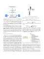
To achieve such a round-trip process, our framework involves four engineering steps on either side of the forward/backward directions to support the code↔code horizontal synchronisation between the evolving template and
user code (see Figure 10). Without loss of generality, in the
following we denote the template and user codes as T and U ,
the modified template and user codes as T 0 and U 0 , and the
merged code as T 0 ⊕ U 0 , respectively.
1) Given that Java codes T, T 0 were generated and synchronised from the model using EMF’s in-built vertical
synchronisation with user’s Java codes U, U 0 except
for those methods that are marked by @generated
INV, we first parse all the @generated INV methods
in T, T 0 , U, U 0 using the JaMoPP parser on top of
the EMFtext framework (see http://www.jamopp.org),
their differences between the T and U 0 are obtained
using the API of the EMFcompare framework (see
http://www.eclipse.org/emf/compare) after the meaningful differences were preprocessed using mct (see
http://sead1.open.ac.uk/mct [4]);
2) The EMF models of T, T 0 , U, U 0 are translated into our
specific UnCal graphs using the reflexion API of the
Ecore, and as a by-product, an UnQL+ transformation
is generated from the meaningful differences between T
and U 0 using the algorithm in Figure 11;
3) The UnCal graphs of T, T 0 , U, U 0 are transformed into
Dot graphs by the GRound_Tram system that preserves the paths from the graph root to any node on
the UnCal graphs in the equivalent Dot graphs;
4) Using the generated UnQL+ transformation and using
the Dot graphs of the U 0 as inputs, the GRoundTram
system also performs a forward transformation to output
a group of Dot graphs that represent T , which is
guaranteed by the one-pass optimisation described in
Section V-C;
5) On the way backwards, using the same UnQL+ transformation on the Dot graphs of the modified template code
T 0 , and the internal graph traceability between T and U 0
kept by the forward transformations in GRoundTram
system, the GRoundTram system performs a backward
transformation to output the Dot graphs that represent
the merged user code, dented by T 0 ⊕ U 0 ;
6) Path-equivalent Uncal graphs corresponding to T 0 ⊕U 0 ;
are re-generated from the resulting Dot graphs;
7) Equivalent EMF model of those Uncal graphs for
T 0 ⊕ U 0 is obtained using an Xtext parser (see
http://www.eclipse.org/Xtext) of Uncal to process the
its abstract syntax using the EMF API;
8) Finally, the merged Java code T 0 ⊕ U 0 is obtained from
the EMF model using the pretty-print function of the
JaMoPP framework.
Fig. 10.
The multi-tier architecture of the blinkit framework.
B. Generating correct UnQL+ transformations
To enable the use of UnQL+ on model-driven software
development, we need to losslessly translate the artifacts
between the code, the UnCal graphs and node-traced graphs
such as Graphviz Dot. This can be done in a multi-tier
fashion [14], and one critical step is to guarantee the correctness of the horizontal (code↔code) synchronisation, that
is to generate a correct UnQL+ bidirectional transformation
from the meaningful differences of the original template code
and the modified user code.
Code Generation from Model. From model to code, we
rely on the existing EMF framework, which provides a wellestablished way to synchronise the model and default code
template (i.e. the code marked by @generated). Reusing
this tool, we do not need to develop any model-to-code vertical
synchronisation tool ourselves. But we distinguish the template
code which users do not want to synchronise by themselves
and those code they want. We also need to automate the
manual code synchronisation process such that it is possible
to make the whole tool chain automated. Thus we intercept
the automated code generation process in EMF as follows:
When generating code from model, for those code marked by
@generated or @generated NOT we use default code
template generated by EMF; and for those code marked with
@generated INV, we use the code of synchronised version
whose traceability are maintained by GRoundTram. Then we
merge these two kinds of code together and expose the merged
code to users.
Transformation between Code, EMF model, UnCal, and
Dot. We choose EMF model as an intermediate representation
of the Java code because (1) EMF model is much more
navigatable than specific abstract syntax trees and (2) it also
make the translation from the abstract syntax to the uncal
generic: any programming language can be supported in
future. EMF reflection mechanisms are used to facilitate the
translations. From EMF to UnCal, an algorithm is designed
to traverse the model and print out the node types, references
and attributes according to the programming language model.
In blinkit, we leverage xtext [?] and EMFtext [?] to do
such translations. For UnCal to EMF model, an algorithm
is designed to reflect the generic language model in UnCal
to a specific EMF language model such as Java. It is found
that xtext is a suitable choice because the generic UnCal
language is not too complex to parse. Though the input of
GRoundTram system can be in UnCal format or in Dot
format, the outputs are always in Dot format. To separate each
tier, we use Dot graphs as GRoundTram inputs universally,
so we have to translate UnCal to Dot and vice versa. We
design and implement an algorithm to translate Dot into
the specific UnCal format, in order to perform backward
transformation. Since GRoundTram could translate UnCal
to Dot, we do not need to design a new algorithm to create
this translation while performing forward transformation. Another problem is that since GRoundTram needs node-traced
graphs while performing backward transformation, we keep
the constants of the node number in Dot graphs resulted
from a forward transformation otherwise the GRoundTram
could not perform backward transformation (i.e. we have to
maintain the traceability of the Dot when do transformation).
While performing backward transformation, we generate the
Dot from the UnCal and reserve the physical relations (i.e.
the node number in Dot) in the Dot graph generated from
forward transformation. Our approach to reserve such physical
relations is based on comparing Dot graphs, which is similar
to the algorithm used for generating UnQL+ (Figure 11).
Generating UnQL+ and Do Bidirectional Transformation using GRoundTram.
After having the Dot graphs, we can use them as inputs and
perform bidirectional transformations through GRoundTram.
Note that GRoundTram needs to use bidirectional transformations specified in the UnQL+ graph transformation language
which extends the UnQL [9] with three simple graph editing
constructs to achieve efficiency and expressiveness [8], namely
Replacing, Deleting, and Extending. Deleting will delete a
subgraph under a specified edge while extending will insert
a subgraph under a specified node, and replacing will replace
a part of the given graph with a new subgraph. As we said in
Section IV, the UnQL+ is used in forward transformation to
transform user code into intermediate code which is the same
as template code. We implemented an algorithm shown in
Figure 11 to generate the UnQ+ transformation automatically
in order to mitigate developers’ burdens. After representing
the Java code that we want to synchronise by Dot graphs, we
can obtain the differences between the Dot graphs and such
differences can be used to generate UnQL+ automatically.
1:
2:
3:
4:
5:
6:
7:
8:
9:
10:
11:
12:
13:
14:
15:
16:
17:
18:
19:
20:
21:
22:
23:
24:
25:
26:
27:
28:
29:
30:
31:
32:
33:
34:
35:
36:
function U N QLG ENERATOR(dotUser, dotTemplate)
rootU ser ← the root node of dotU ser
rootT emplate ← the root node of dotT emplate
MatchingDot(rootUser, rootTemplate)
end function
function M ATCHING D OT(nodeU ser, nodeT emplate)
edgeSetU ser ← outgoing edges of nodeU ser
edgeSetT emplate ← outgoing edges of nodeT emplate
for all edgeU ser ∈ edgeSetU ser do
f lag = false
childN odeU ser ← the target node of edgeU ser
for all edgeT emplate ∈ edgeSetT emplate do
if edgeU ser = edgeT emplate then
f lag = true
childN odeT emplate ←
the target node of edgeT emplate
MatchingDot(childNodeUser, childNodeTemplate)
end if
end for
if f lag = false then
DeleteConstructor(childNodeUser)
end if
end for
for all edgeT emplate ∈ edgeSetT emplate do
f lag = false
childN odeT emplate ← the target node of edgeT emplate
for all edgeU ser ∈ edgeSetU ser do
if edgeT emplate = edgeU ser then
f lag = true
end if
end for
if f lag = false then
ExtendConstructor(childNodeTemplate)
end if
end for
end function
Fig. 11.
Procedure of generating UnQL+.
The UnQL+ generated by our approach only contains Deleting and Extending operations. The Replacing operations can
be replaced by a Deleting and an Extending operation. The
UnQLGenerator algorithm starts node matching from root
in Dot graphs. For each node pair, we compare their outgoing
Del et i ng
Ext endi ng
1
1
a
2
e
f
Subgr aph 2
Subgr aph 1
g
Subgr aph 3
d
2
Subgr aph 1
c
Subgr aph 3
Subgr aph 2
a
4
h
Subgr aph 4
d
2
Subgr aph 1
1
b
Subgr aph 3
c
4
3
h
f
Subgr aph 3
( c)
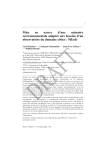
Fig. 12.
g
f
( b)
3
f
d
Subgr aph 1
1
b
4
e
( a)
a
c
b
3
2
4
3
d
a
c
b
Subgr aph 1
( d)
The overall process of the blinkit framework.
edges’ labels. If we find one edge which exists in the user’s
graph but does not exist in the template’s graph, that means
deletion occurs and we will generate a Deleting operation
to delete the subgraph beneath the node under comparison
(line 20-22); if the two edges have the same labels, we will
do node matching for their children recursively (line 13-18).
Similarly, for those edges that template’s graph has but user’s
graph does not, we need an Extending operation (line 32-34).
For extending operation, we have to record the subgraph that
need to be inserted. To generate UnQL+, path information
composed by edge labels are needed in order to denote which
part should be deleted or inserted. Since the labels on the
outgoing edges of one node are different from each other in
our Dot graphs, such paths which reflect the changes between
two Dot graphs are unique. We have to obtain such paths to
generate UnQL+ and the uniqueness of the paths guarantees
the correctness of our UnQL+ generated algorithm (i.e. if there
are two outgoing edges of a node with the same label, this
algorithm may not generate desired UnQL+).
An example is shown to illustrate this algorithm (Figure 12).
Suppose we want to transform a graph shown as Figure 12(a)
into Figure 12(d), then we have to delete the edge e, g and
subgraph subgraph 2, and insert the edge h and subgraph
4. The algorithm first generate Deleting operations which
could transform Figure 12(a) into Figure 12(b). Note that the
Deleting operations contain the deletion of subgraph 3 and
edge f though they should not be deleted. This is because
when the algorithm deletes the edge g, it will also delete its
pointed subgraphs (subgraph 3) and the edges connect to those
subgraphs (edge f ). Then when generating extending operation, the algorithm not only inserts the edge h and subgraph
4, but also inserts the edge f and subgraph 3 again. This extra
deletion and insertion may reduce the transformation efficiency
and more efficient algorithms should be explored in the future
work. Comparison algorithms for trees and graphs based on
dynamic programming [15] may be adopted.
C. Derivation of a One-Pass Transformation
The automatically generated UnQL+ transformations, like
SQL queries, are not optimal unless some optimisation can be
made. One bottleneck of its performance is that the pairs of
difference elements as basic operations Replacing, Deleting or
Extending on the source code are typically multiple, while the
original form of UnQL+ would sequentially compose them.
Ideally, these operations should be composed as one single
graph transformation such that GRound_Tram could attain
results in one-pass of the structure. In theory, the composition
of general UnQL+ transformations have to be sequential.
However, the transformations we obtained from the diff results
have nice properties that make it possible to compose the basic
operations without any side-effects. The rationale is given
below.
Let e1 , e2 , . . . , en be a sequence of the editing operations
obtained above, where any two editing operations, ei and
ej , are independent in the sense that neither insertion nor
deletion is done on an inserted/deleted part again. This can
be formalised as that for any i and j, ei ◦ ej = ej ◦ ei holds.
We would like to show that any editing sequence can be
automatically transformed to a one-pass traversal of graphs.
Our algorithm consists of two steps: We first map the editing
sequence to composition of a set of graph transformation
where each graph transformation corresponding to an editing
operation, and then try to fuse the composition into a single
one-pass graph transformation in terms of a structural recursion in UnCal.
1) Mapping from Editing Sequence to Composition of
Graph Transformations: First, as discussed before, each editing operation corresponds to a simple graph transformation in
UnQL+. To be precise, let p denotes the path from the root
to the node n (i.e., a sequence of edge labels from the root to
the node n) of in the graph $db. Then, the editing operation
e($db) for deleting a subgraph {l : $g} rooted at the node n
can be translated to E($db):
delete p → {l : $g} in $db
0
and the edition operation e ($db) for inserting a subgraph G
to the node n to E 0 ($db):
extend p → $g with G in $db.
Now a sequence of editing operations e1 , e2 , . . . , en
corresponds to composition of graph transformations of
E1 ($db), E2 ($db), . . . , En ($db), that is,
E1 (E2 (. . . (En ($db))).
2) Fusion of Composition of Graph Transformations:
GRoundTram provides a powerful fusion mechanism that can
automatically fuse a composition of graph transformations into
one so that unnecessary inter meditate graph passed between
the graph transformation can be eliminated. We could apply
this general fusion mechanism, but we can do better based on
the fact that each graph transformation is independent from
each other. Thus we develop a specialised but more efficient
fusion algorithm.
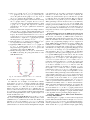
Our idea is to construct an action tree from the editing
sequence and then map the action tree to a one-pass transformation. For an action tree, leaves are marked with two action
markers D(l) and I(G), denoting respectively deletion of a
graph pointed by the edge l when possible and insertion of
a graph G. Figure 13 gives an example action tree, which
Fig. 13.
An action tree
describes the intention of that, given a graph, for the node
reached by the path of a.b do deletion, for the node reached
by the path b.a do deletion, and for the node reached by the
path b.c do insertion. In fact, an action tree is nothing but
a tree automaton, and it is known that a tree automaton can
be mapped to a structural recursion in UnCal that traverses
graphs only once [9]
Let us show that a sequence of editing operations can be
represented by an action tree. First, it is clear that a single
editing operation can be represented by a simple action tree
(which is actually a tree where each node has just a single
child.). Now given two action trees t1 and t2 , we can combine
them to merge(t1 , t2 ), satisfying that (1) any action in t1 or
t2 appears in merge(t1 , t2 ) and any action in merge(t1 , t2 )
appears in in t1 or t2 and (2) there is no node that has
two outgoing edges with the same labels. The algorithm
merge(t1 , t2 ) is define as follows.
merge((), t2 )
merge(t1 , ())
merge(t1 ∪ t01 , t2 )
merge({l : t1 }, {l : t02 } ∪ t2 )
merge({l : t1 }, t2 )
=
=
=
=
=
t2
t1
merge(t1 , merge(t01 , t2 ))
{l : merge(t1 , t02 )} ∪ t2
{l : t1 } ∪ t2
With this merge operation, we can merge all editing operations
into an action tree.
VI. E VALUATION
In order to evaluate the benefits of the framework, we assess
two research questions. First, does blinkit work correctly
on the examples without human intervention? Second, given
that the illustrative example is constructed, is there realistic
cases in an open-source MDD software development project
where invariant traceability links can be synchronised using
blinkit? The first question needs to be answered first since
only a working blinkit prototype can bring benefits to
the users if it is beneficial. The second also needs to be
answered since if there is no evidence blinkit is needed in
the practice, one might question the usefulness in reality. To
answer these questions, we conducted two sets of experiments.
Correctness. In the first experiment we create a model in
EMF framework as the one illustrated earlier and generate the
default Java source code initially. Table ?? shows the number
of elements at various abstraction levels in the generated
code. There is only 1 class (i.e., Entity) and 1 attribute (i.e.,
name) respectively in the EMF metamodel, the code generated
by EMF has 2 classes (i.e., Entity, EntityPackage) and 1
attribute (i.e., name) annotated by @model. In terms of the
number of @generated attributes, there are respectively 8
classes, 48 attributes and 10 methods generated in 3 packages.
TABLE I
S TATISTICS ON THE E NTITY EXAMPLE
Abstraction
packages
classes
declarations
method bodies
| @generated|
3
9
48
9
| @model|
0
2
1
0
Currently, blinkit only supports synchonisation between
method bodies which user likely to change for different
behaviours according to our experience.
For evaluating the correctness of blinkit, we manually modified those 9 methods annotated by @generated
into @generated INV. The blinkit tool generated an
‘identity’ UnQL+ transformation for each of the invariant
traceability @generated INV. Then we manually modified
individual @generated INV methods in three ways: By
adding, removing and replacing 1 or 2 statements to simulate a
possible change on the user code. In parallel to that, we applied
the Rename Class and the Rename Method refactorings to the
3 elements in the model that were annotated by the @model
markers to have impact on the template code.
The simulated changes to the newly generated template code
may intersect with the changes introduced by user, e.g., by
renaming “name” to “iD”, in those cases the changes should
be merged by blinkit. For correctness, we checked the
merged results manually to see whether they preserve both
changes in the model and in the user code. On the other hand,
if the changes of the @model do not affect the changes to the
@generated INV elements by the user, then all changes
introduced by the user were preserved.
Intersection of the changes in @generated NOT,
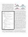
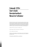
@generated and @model. To answer the second question, we first extracted from the CVS repository all revisions of Java code from the GMF project according to
http://archive.eclipse.org, which covers about 6
years period between Aug 14 2005 and Aug 31, 2011. According to this repository, in total there have been 28,070 revisions
including all the ones before the deleted files were placed in
the Attic subfolders. In order to understand how many times
the model parts have changed, we rely on the EMF convention
that all modeling elements in the generated template code
have been annotated with the @model markers. Therefore,
we extracted the interface APIs that were marked by @model
using the normalisation and clone detection technique reported
in our earlier work [4]. In this way, all meaningful differences
for the model can be found among the 1185 pairs of possible
revisions (we only compare those revisions on the same files).
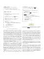
There are 178 pairs of meaningful changes, ranging from
2005/08/14 till 2011/02/28. There is no longer changes after
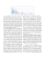
that. Figure 14 shows the distribution of 178 @model changes
over this period of time.
Next, we used a different normalisation on the same dataset,
this time filtering only those methods that have been annotated by @generated NOT markers amongst 1,314 Java
classes. For these Java methods, we moved their implemen-
tation in the body into the <!-begin-user-doc> ...
<!--end-user-doc> pairs in the Javadoc comments, and
changed their annotations into @generated such that the
code generator will overwrite the user code with the template
code, while the user modifications are still available in the
comment. Finally, we compared the differences between the
template and user codes, in order to see whether the changed
@model elements appear in these method bodies. If they do,
then we have confirmed that the bidirectional transformation
could be useful in practice because the user code was different
from the template code indeed, and those differences would
interact with the modification of the model in the immediate
revisions following the timestamps.
Throughout the dataset, it is found that 15,223 revisions
amongst the total of 28,070 revisions (i.e., 54%) will be influenced by the changes of the @model elements, and on average
146,415/15,223=9.61 of the modeling elements are referenced
by the method implementation of the @generated NOT
parts of these Java revision files.
We briefly summarise the threats to validity and some
limitations in this study:
Construct validity: Instead of synchronising for the whole
classes or packages, we focus on synchronising changes to
the method bodies. The reason for this choice is practical
as most of the time users would customise the behaviour
of the default class, rather than rewriting them completely.
Also to note that a modification to method bodies is often
required because the template code would otherwise raise
UnsupportedOperationException.
External validity: blinkit is built on top of existing
open-source MDD toolsets EMF, EMFtext, JaMoPP and a
standalone transformation systems TXL. It also integrates two
research prototypes groundtram [16] and mct [4] which are
freely available to download. The subject case study is also an
open-source one whose CVS repository is publicly available.
Internal validity: Although studying committed changes
on the model in the GMF repository may be conservative, it
is the only publicly available source code that we can rely on.
It can be argued that editing changes that were not committed
may have more opportunity of synchronisation, however we
have to make conservative estimates on the benefits without
empirically monitoring developers over their shoulders.
VII. R ELATED WORK
We compare blinkit to the related work in the areas
of traceability, model-code co-evolution, and bidirectional
transformations.
Precise traceability. Automated software document-code
traceability recovery has been studied by researchers from
many angles since requirements traceability was proposed [3]:
The review of the best practices in this field [17] suggests
that automated techniques such as vector spaces [18], [19],
LSI [20] are useful when part of the dataset relies on ambiguous documentation such as requirements, manuals and
bug reports. It is expensive to obtain expert judgements for
large applications [21] and to obtain high-quality inputs [22].
Fig. 14.
Distribution of @model changes in the CVS repository indicates that metamodels used in the evolving GMF project getting stabilised
Incremental techniques have been proposed to analyse evolving traceability links [20] for better efficiency, however, precision cannot be greatly improved. Auxilliary information
from programs such as callgraphs or traces [22] could help
improve the precision to some extent, but it is still largely
expensive to gain better results through feedback [23]. On
the other hand, the abstraction gap between models and code
is much narrower that that between requirements document
and code, thus precise tracing has been considered through
maintaining semi-automated refactorings [24]. However, such
refactorings are also expensive to construct, thus affordable
only for medium-sized security software applications. In this
work, we address the problem for general software projects
that scales while the MDD has been applied.
Invariant traceability for model/code co-evolution. When
projects evolve, MDD methods face additional challenges:
not only do artifacts such as models or code change over
time, their changes also need to be propagated in order
to maintain consistency even when artefacts are at different
levels of abstraction. Co-evolution needs to be studied between
models and code, between behavioural and structural models,
or even between code and programming languages [25].
Modifications to a model must be reflected on the corresponding code in order to keep the model and the code
synchronised. Code generators exist to automatically generate
code from UML models [26]–[28]. However, in practice the
code is often updated manually after it has been generated,
and it is therefore necessary to reflect those changes back
to the corresponding model. Round-trip engineering (RTE)
is one-way to synchronise UML diagrams and code [29].
However, combining code generation and reverse engineering
approaches is still not sufficient: Changing independently,
models and code need to be merged first; Secondly, since
models are generally at a higher level of abstraction than
code, not all changes made to the code can be reflected back
to models. There may be changes on a level of abstraction
that is too detailed for the model. Therefore, for every model,
there exist many different versions of the code that implement
the model correctly. Giese and Wagner [30] use triple graph
grammars for RTE, but their approach is limited to elements
that have a correspondance in the model. Other approaches,
like Van Paesschen et al.’s [31], assume that both artifacts can
be represented in a common representation. Fujaba [32] is
yet another RTE approach that can generate Java code from
UML class diagrams, and regenerated class diagrams from
modified Java code, as long as developers follow Fujaba’s
naming conventions and implementation concepts. State-ofthe-art RTE tools such as EMF/GMF make use of annotations
to separate the portions of generated and user modified code,
yet it is largely manual to maintain the correspondence of
@generated NOT elements. In order to allow one to
preserve changes made to the code when the model is updated
and the code subsequently regenerated, tools such as the EMF
and GMF frameworks allow developers to annotate portions
of the code to make sure that they will not be overwritten
by the code generator in the future. While this solution
allows one to protect custom code from being overwritten,
over time, the model and the code will become increasingly
inconsistent, as some changes performed on the model will not
be reflected in the code. The co-evolution of GMF project has
been studied [33] for synchronising the four different EMF
metamodels (model↔model) used by the project. Although
we also uses the same case study to evaluate the benefits, our
focus is on automating the code↔code synchronisations for
method bodies.
Bidirectional transformation [34], [35] has been recently
widely studied by researchers from different communities of
programming language, software engineering, and database.
It has many potential applications in software development,
including model synchronization [5], [36], round-trip engineering [37], software evolution [38], and multiple-view software
development [39]. Our work shows that we can move from
“potential” to “practical”; we achieve scalability by proposing
a two-layer bidirectional transformation framework, hiding
difficulties in writing bidirectional transformation by automatic
deriving it from a sequence of editing operations, and widening
its application scope by treating general graphs.
VIII. C ONCLUSIONS AND FUTURE WORK
In this paper, we presented a model-driven development
method, supported by the blinkit prototype, to maintain
the invariant traceability between model and code through
bidirectional transformations. Using this method, if the code
is annotated by @generated INV, a bidirectional transformation will be generated which correctly propagates changes
in both directions. We tested our framework by the example
shown in Section III and observed empirically how often
blinkit can be used to maintain the invariant traceability
based on the dataset of the CVS repository of GMF, a widelyused model-driven development project. It is also observed that
applying the method to the project can deliver more benefits
since its metamodels changes more frequently.
In the case study, we also found that more changes were
derived from the evolving model than from the evolving
template. Current work considers a basic form of invariant
traceability where all meaningful changes are synchronized,
regardless whether they were derived from the template or
from the model. In future work, we will extend the syntax
and semantics of @generated INV to further differentiate
the changes from model from those from the templates.
R EFERENCES
[1] L. Angyal, L. Lengyel, and H. Charaf, “A Synchronizing Technique
for Syntactic Model-Code Round-Trip Engineering,” in ECBS ’08:
Proceedings of the 15th Annual IEEE International Conference and
Workshop on the Engineering of Computer Based Systems. Washington,
DC, USA: IEEE Computer Society, 2008, pp. 463–472.
[2] “Eclipse Modeling Framework Project,” Online manual, 2010. [Online].
Available: http://www.eclipse.org/modeling/emf/
[3] O. C. Z. Gotel and A. C. W. Finkelstein, “An analysis of the requirements
traceability problem,” in RE ’94: Proceedings of the First International
Conference on Requirements Engineering, 1994, pp. 94–101.
[4] Y. Yu, T. T. Tun, and B. Nuseibeh, “Specifying and detecting
meaningful changes in programs,” in 26th IEEE/ACM International
Conference On Automated Software Engineering, November 2011, to
appear. [Online]. Available: http://oro.open.ac.uk/29450/
[5] Y. Xiong, D. Liu, Z. Hu, H. Zhao, M. Takeichi, and H. Mei, “Towards
automatic model synchronization from model transformations,” in ASE,
R. E. K. Stirewalt, A. Egyed, and B. F. 0002, Eds. ACM, 2007, pp.
164–173.
[6] OASIS, “XML Metadata Interchange,” Online manual, May 2002.
[Online]. Available: http://xml.coverpages.org/xmi.html
[7] S. Hidaka, Z. Hu, K. Inaba, H. Kato, and K. Nakano, “GRoundTram:
An integrated framework for developing well-behaved bidirectional
model transformations (short paper),” in 26th IEEE/ACM International
Conference On Automated Software Engineering (ASE 2011), Oread,
Lawrence, Kansas, USA, 2011.
[8] S. Hidaka, Z. Hu, H. Kato, and K. Nakano, “Towards a compositional
approach to model transformation for software development,” in SAC
’09: Proceedings of the 2009 ACM symposium on Applied Computing.
New York, NY, USA: ACM, 2009, pp. 468–475.
[9] P. Buneman, M. F. Fernandez, and D. Suciu, “UnQL: a query language
and algebra for semistructured data based on structural recursion,” VLDB
Journal: Very Large Data Bases, vol. 9, no. 1, pp. 76–110, 2000.
[10] S. Hidaka, Z. Hu, K. Inaba, H. Kato, K. Matsuda, and K. Nakano,
“Bidirectionalizing graph transformations,” in ICFP 2010. ACM Press,
2010, pp. 205–216.
[11] J. Ellson, E. R. Gansner, E. Koutsofios, S. C. North, and G. Woodhull,
“Graphviz and dynagraph - static and dynamic graph drawing tools,” in
GRAPH DRAWING SOFTWARE. Springer-Verlag, 2003, pp. 127–148.
[12] S. Hidaka, Z. Hu, K. Inaba1, H. Kato, K. Matsuda, and K. Nakano,
“Groundtram version 0.9.0 user manual,” 2010. [Online]. Available:
http://www.biglab.org/
[13] P. Buneman, M. Fernandez, and D. Suciu, “Unql: a query language
and algebra for semistructured data based on structural recursion,” The
VLDB Journal, vol. 9, no. 1, pp. 76–110, 2000.
[14] Y. Yu, Y. Lin, Z. Hu, S. Hidaka, H. Kato, and L. Montrieux, “blinkit:
Maintaining invariant traceability through bidirectional transformations
– a technical report,” Tech. Rep., September 2011.
[15] “Xtext,” Online manual, 2011. [Online]. Available: http://www.eclipse.
org/Xtext/
[16] “EMFtext,” Online manual, 2011. [Online]. Available: http://www.
emftext.org/index.php/EMFText
[17] W. Yang, “Identifying syntactic differences between two programs,” in
Software - Practice and Experience, vol. 21, 1991, pp. 739–755.
[18] “The Big Project,” Online manual, 2009. [Online]. Available:
http://www.biglab.org/
[19] J. Cleland-Huang, B. Berenbach, S. Clark, R. Settimi, and E. Romanova,
“Best practices for automated traceability,” IEEE Computer, vol. 40,
no. 6, pp. 27–35, 2007.
[20] J. H. Hayes, A. Dekhtyar, and S. K. Sundaram, “Advancing candidate
link generation for requirements tracing: The study of methods,” IEEE
Trans. Software Eng., vol. 32, no. 1, pp. 4–19, 2006.
[21] G. Antoniol, G. Canfora, G. Casazza, A. D. Lucia, and E. Merlo,
“Recovering traceability links between code and documentation,” IEEE
Trans. Software Eng., vol. 28, no. 10, pp. 970–983, 2002.
[22] H. Jiang, T. N. Nguyen, I.-X. Chen, H. Jaygarl, and C. K. Chang,
“Incremental latent semantic indexing for automatic traceability link
evolution management,” in ASE. IEEE, 2008, pp. 59–68.
[23] G. Antoniol, J. H. Hayes, Y.-G. Guéhéneuc, and M. D. Penta, “Reuse
or rewrite: Combining textual, static, and dynamic analyses to assess
the cost of keeping a system up-to-date,” in 24th IEEE International
Conference on Software Maintenance (ICSM 2008), 2008, pp. 147–156.
[24] A. Egyed and P. Grünbacher, “Supporting software understanding with
automated requirements traceability,” International Journal of Software
Engineering and Knowledge Engineering, vol. 15, no. 5, pp. 783–810,
2005.
[25] A. D. Lucia, F. Fasano, R. Oliveto, and G. Tortora, “Recovering traceability links in software artifact management systems using information
retrieval methods,” ACM Trans. Softw. Eng. Methodol., vol. 16, no. 4,
2007.
[26] Y. Yu, J. Jürjens, and J. Mylopoulos, “Traceability for the maintenance
of secure software,” in 24th IEEE International Conference on Software
Maintenance (ICSM 2008), 2008, pp. 297–306.
[27] T. Mens, M. Wermelinger, S. Ducasse, S. Demeyer, R. Hirschfeld,
and M. Jazayeri, “Challenges in software evolution,” in IWPSE ’05:
Proceedings of the Eighth International Workshop on Principles of
Software Evolution. IEEE Computer Society, 2005, pp. 13–22.
[28] A. Rountev, O. Volgin, and M. Reddoch, “Static control-flow analysis
for reverse engineering of uml sequence diagrams,” in Proceedings of
the 6th ACM SIGPLAN-SIGSOFT workshop on Program analysis for
software tools and engineering, ser. PASTE ’05. ACM, 2005, pp. 96–
102.
[29] M. Keschenau, “Reverse engineering of uml specifications from java
programs,” in Companion to the 19th annual ACM SIGPLAN conference
on Object-oriented programming systems, languages, and applications,
ser. OOPSLA ’04. ACM, 2004, pp. 326–327.
[30] Y.-G. Guéhéneuc, “A reverse engineering tool for precise class diagrams,” in Proceedings of the 2004 conference of the Centre for
Advanced Studies on Collaborative research, ser. CASCON ’04. IBM
Press, 2004, pp. 28–41.
[31] T. Hettel, M. Lawley, and K. Raymond, “Model synchronisation: Definitions for round-trip engineering,” in Theory and Practice of Model
Transformations, ser. Lecture Notes in Computer Science. Springer
Berlin / Heidelberg, 2008, vol. 5063, pp. 31–45.
[32] H. Giese and R. Wagner, “Incremental model synchronization with triple
graph grammars,” in Model Driven Engineering Languages and Systems,
ser. Lecture Notes in Computer Science. Springer Berlin / Heidelberg,
2006, vol. 4199, pp. 543–557.
[33] E. Van Paesschen, W. De Meuter, and M. D’Hondt, “Selfsync: A
dynamic round-trip engineering environment,” in Model Driven Engineering Languages and Systems, ser. Lecture Notes in Computer
Science. Springer Berlin / Heidelberg, 2005, vol. 3713, pp. 633–647.
[34] T. Klein, U. A. Nickel, J. Niere, and A. Zündorf, “From uml to java
and back again,” University of Paderborn, Tech. Rep., 1999.
[35] D. D. Ruscio, R. Lämmel, and A. Pierantonio, “Automated co-evolution
of gmf editor models,” in SLE, ser. Lecture Notes in Computer Science,
B. A. Malloy, S. Staab, and M. van den Brand, Eds., vol. 6563. Springer,
2010, pp. 143–162.
[36] K. Czarnecki, J. N. Foster, Z. Hu, R. Lämmel, A. Schürr, and J. F. Terwilliger, “Bidirectional transformations: A cross-discipline perspective,”
in International Conference on Model Transformation (ICMT 2009).
LNCS 5563, Springer, 2009, pp. 260–283.
[37] Z. Hu, A. Schürr, P. Stevens, and J. F. Terwilliger, “Dagstuhl seminar
on bidirectional transformations (bx),” SIGMOD Record, vol. 40, no. 1,
pp. 35–39, 2011.
[38] M. Antkiewicz and K. Czarnecki, “Design space of heterogeneous synchronization,” in GTTSE ’07: Proceedings of the 2nd Summer School on
Generative and Transformational Techniques in Software Engineering,
2007.
[39] Michal Antkiewicz and Krzysztof Czarnecki, “Framework-specific modeling languages with round-trip engineering,” in MoDELS 2006: Pro-
ceedings of the 9th International Conference on Model Driven Engineering Languages and Systems. Springer-Verlag, 2006, pp. 692–706.
[40] R. Lämmel, “Coupled Software Transformations (Extended Abstract),”
in First International Workshop on Software Evolution Transformations,
Nov. 2004.
[41] M. Garcia, “Bidirectional synchronization of multiple views of software
models,” in Proceedings of DSML-2008, ser. CEUR-WS, vol. 324, 2008,
pp. 7–19.