1
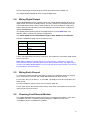
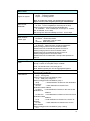
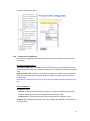
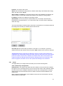
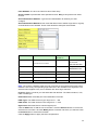
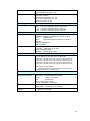
Wire the digital input just like wiring the power input introduced in chapter 2.2.
The JetNet 5628G-R/5828G-R doesn’t support Digital Input.
2.4
Wiring Digital Output
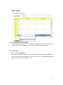
JetNet 5628G/5828G provide 2 digital outputs and JetNet 5628G-R/5828G-R provide 1
digital output, also known as Relay Output. The relay contacts are energized (open) for
normal operation and will close for fault conditions. The fault conditions include power
failure, Ethernet port link break or other pre-defined events which can be configured in
JetNet 5628G/5828G UI.
The default (without power) state of the Digital Output is normal OPEN state. The
ON/OFF state is controlled by software configuration.
The JetNet 5628G-R and JetNet 5828G-R support both OPEN and CLOSE mode.
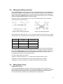
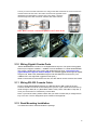
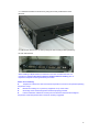
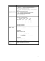
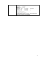
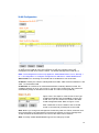
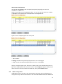
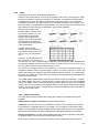
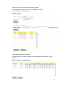
Follow the installation guide print in the panel to wire.
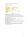
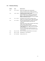
Pin No.
State
1
NO (Normal Open)
2
COM
3
COM
4
NC (Normal Close)
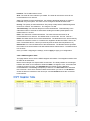
Loosen the Digital Output screw by screw drive, then tighten the screw after digital output
wire is connected.
Note: When installed the Digital Output in your environment, remember to check the
environment protection, like Surge protection of the connected device. The digital output
contact of the JetNet 5628G/5828G do not provide high level Surge protection, this should
be protected by connected device.
2.5
Wiring Earth Ground
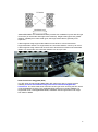
To ensure the system will not be damaged by noise or any electrical shock, we suggest
you to make exact connection with JetNet 5628G/5828G with Earth Ground.
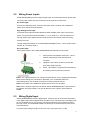
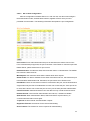
For AC input, the 3 pin include V+, V- and GND. The GND pin must be connected to the
earth ground.
For High Voltage DC (HVDC) input, PE is Protective Earth pin.
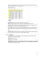
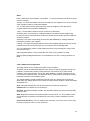
For DC input, loosen the earth ground screw by screw drive; then tighten the screw after
earth ground wire is connected.
2.6
Choosing Fast Ethernet Module
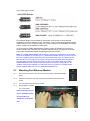
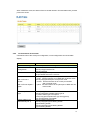
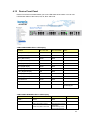
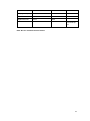
The JetNet 5628G/5828G provides several types of Fast Ethernet modules. There are 8
10/100Base-TX ports, 4 100Base-FX/SC ports plus 2 100Base-FX SFP and 4
10/100Base-TX plus 4 100Base-FX modules.
10