1
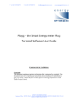
AMBIENT ASSISTED LIVING SYSTEM
LOCAL MONITORING
CONSOLE
Henrique Madeira
Integrated Master
in Biomedical Engineering
Faculty of Sciences and
Technology
University of Coimbra
2008/2009
© Copyright ISA 1990 – 2008. All Rights Reserved
A CKNOWLEDGEMENTS
I would like express my gratitude to all the hands and minds that, in some way, have taken
part and contributed in this project‘s development.
My special thank to João Alves and Soraia Rocha for all the teaching, advising, guidance,
patience, interest, motivation, time and effort spent on pushing me forward.
I would also like to acknowledge José Luís Malaquias for caring about my expectations and for
the opportunity to be part of a project that mattered.
At last, I would like to show my deep appreciation for those that, without asking, had to live
with Ambient Assisted Living, monitoring consoles, Linux and so many other ―strange
concepts‖ for the past twelve months.
Thank you all.
Ambient Assisted Living System - Local Monitoring Console
i
A BSTRACT
Ambient Assisted Living is a concept of growing importance in today‘s ageing society, as life
expectancy and elderly people‘s percentage increases and, with it, healthcare system‘s
efficiency becomes urgent. AAL can be defined as life in a supportive environment.
An AAL system should ideally be implemented as a series of modular, interoperable and
intercommunicating concepts, aiming to build a sort of ―virtual intelligence‖ around the user.
In recent years, there have been some attempts to create concentration modules for
monitoring systems but, so far, none has been comprehensive enough to support an
integrated AAL system. This project invests on a low-budget solution supporting different,
already existing, health and environmental information-collection technologies to create such
system.
Project‘s research and development resulted in a prototype software solution running over a
Linux-based firmware, on a standard wireless router platform, with support for two different
health monitoring devices and one energy-consumption monitor. Concept‘s validity has been
proven and path for desired full-feature solution is now open.
Ambient Assisted Living System - Local Monitoring Console
ii
R ESUMO
Com o aumento da esperança média de vida, da percentagem de idosos e uma consequente
urgência de melhoria de eficiência na prestação de cuidados de saúde, o conceito de Ambient
Assisted Living tem vindo a ganhar importância na sociedade actual. Este conceito pode ser
definido como vida em ambiente de apoio.
Idealmente, um sistema de AAL deve ser implementado como uma série de conceitos
modulares, inter-operacionais e inter-comunicantes, com o objectivo de construir uma
espécie de ―inteligência virtual‖ em torno do utilizador.
Em anos recentes, têm sido criados lançados alguns projectos de módulos concentradores
para sistemas de monitorização, sendo que, até hoje, nenhum apresentou abrangência
suficiente para suportar um sistema integrado de AAL. Este projecto aposta numa solução de
custo reduzido com suporte de diferentes tecnologias já existentes para a recolha de
informação clínica e ambiental, que permita a criação de tal sistema.
O projecto de investigação e desenvolvimento resultou numa solução de software protótipo, a
correr sobre um firmware baseado no sistema Linux, numa plataforma standard de router
wireless com suporte para dois tipos de monitores de sinais vitais e um monitor de consumos
energéticos. A validade do conceito foi comprovada e o caminho para uma solução completa
encontra-se agora aberto.
Ambient Assisted Living System - Local Monitoring Console
iii
I NDEX
Acknowledgements ............................................................................................ i
Abstract .........................................................................................................ii
Resumo ......................................................................................................... iii
Index ............................................................................................................ iv
List of Tables .................................................................................................. vi
List of Figures ................................................................................................ vii
Chapter 1: Introduction ....................................................................................... 1
1.1 Domain and Motivation.............................................................................. 1
1.2 Objectives ............................................................................................. 2
1.3 Document Structure and Organization ........................................................... 2
Chapter 2: Project Management ............................................................................ 3
2.1 Team ................................................................................................... 3
2.2 Tasks ................................................................................................... 3
2.3 Planning ............................................................................................... 4
Chapter 3: Problem Analysis ................................................................................. 5
3.1 State of the Art ....................................................................................... 5
3.1.1 Vera, by Mi Casa Verde ..................................................................... 5
3.1.2 Wellness Connected™, by A&D Medical .................................................. 6
3.1.3 Home Control Center, by There. Corporation .......................................... 7
3.2 Initial Idea ............................................................................................. 8
3.3 Opportunity: Linux & Routers...................................................................... 9
3.4 Firmware Selection .................................................................................. 9
3.5 Hardware Selection ................................................................................ 10
Chapter 4: System‘s Architecture......................................................................... 13
4.1 System Features & Requirements ............................................................... 14
4.1.1 Hardware .................................................................................... 14
4.1.2 Software ..................................................................................... 18
4.1.3 Short Range Communication Protocols ................................................. 19
Chapter 5: Software Development ........................................................................ 21
5.1 Web Interface ...................................................................................... 22
5.1.1 Layout and Organization .................................................................. 22
5.1.2 HTML forms & CGI programs ............................................................. 23
5.2 Monitoring Modules ................................................................................ 25
5.2.1 Monitoring Session Boot – mntrcnsld .................................................... 25
5.2.2 Data Processing ............................................................................. 25
5.2.3 Data Collection and Parsing .............................................................. 27
5.2.4 Demonstration Applications .............................................................. 30
Chapter 6: Prototyping and Testing ...................................................................... 34
6.1 Prototypes ........................................................................................... 34
6.1.1 Prototype #1 ................................................................................ 34
6.1.2 Prototype #2 ................................................................................ 35
6.2 Performed Tests .................................................................................... 35
Ambient Assisted Living System - Local Monitoring Console
iv
6.2.1 Web Interface Testing ..................................................................... 36
6.2.2 Monitoring Process testing................................................................ 37
6.2.3 Identified Bugs .............................................................................. 38
Chapter 7: Conclusions and Future Work ................................................................ 40
7.1 Project Status ...................................................................................... 40
7.2 Possible Future Developments ................................................................... 41
7.3 Final Appreciation ................................................................................. 42
Bibliography .................................................................................................. 43
Annexes ........................................................................................................ 46
Annex A: Web interface main page ................................................................... 46
Annex B: Configuration files‘ structuring ............................................................ 47
Annex C: scan.cgi application‘s output .............................................................. 48
Ambient Assisted Living System - Local Monitoring Console
v
L IST OF T ABLES
Table 1 - Project's development team ..................................................................... 3
Table 2 - Selected routers main characteristics (15) .................................................. 11
Table 3 - ASUS WL-500Gp hardware features (16) ..................................................... 14
Table 4 - Bluetooth Class features (17) .................................................................. 15
Table 5 - iMeterPlug's stored data ........................................................................ 27
Table 6 - Prototype #1 setting............................................................................. 34
Table 7 - Creation of the demonstration prototype ................................................... 35
Table 8 - Test 1: adding a device to the network...................................................... 36
Table 9 - Monitoring process testing ..................................................................... 38
Table 10 - Channel bitmask valid options ............................................................... 39
Ambient Assisted Living System - Local Monitoring Console
vi
L IST OF F IGURES
Figure 1 - Project's Gantt Diagram.......................................................................... 4
Figure 2 - Vera home-control gateway ..................................................................... 6
Figure 3 - Wellness Connected system ..................................................................... 7
Figure 4 - There.'s Home Control Center .................................................................. 8
Figure 5 - The ASUS WL-500G Premium Wireless Broadband Router ............................... 12
Figure 6 - Monitoring console‘s conceptual scheme ................................................... 13
Figure 7 - Bioplux Mini Research .......................................................................... 16
Figure 8 - NONIN 4100 digital pulse oximeter .......................................................... 17
Figure 9 - ISA's iMeterPlug .................................................................................. 17
Figure 10 - Software solution‘s general architecture ................................................. 21
Figure 11 - Demonstration modules used for direct transmission of the data .................... 22
Figure 12 - Web Interface site-map ...................................................................... 23
Figure 13 - Adding nearby devices procedure using the 'scan' tool ................................. 24
Figure 14 - mntrcnsls main function's flowchart ....................................................... 25
Figure 15 - Processing applications flowchart .......................................................... 26
Figure 16 - receiveBioplux's FSM flowchart ............................................................. 29
Figure 17 - receivePlogg's FSM flowchart ................................................................ 30
Figure 18 – oxDemo‘s FSM flowchart ..................................................................... 31
Figure 19 - ploggDemo's FSM flowchart .................................................................. 33
Ambient Assisted Living System - Local Monitoring Console
vii
A CRONYMS
AAL
Ambient Assisted Living
CFE
Common Firmware Environment
CGI
Common Gateway Interface
CSS
Cascade Style Sheets
ECG
Electrocardiography
EDF
European Data Format
EDR
Enhanced Data Rate
EMG
Electromyography
GB
Gigabyte (1Gb = 230 bytes)
GPL
GNU Public License
GPRS
General packet radio service
GSM
Global System for Mobile Communications
HTML
Hyper Text Markup Language
IP
Internet Protocol
JTAG
Standard Test Access Port and Boundary-Scan
Architecture
LED
Light-Emitting Diode
M2M
Machine to Machine
MAC
Media Access Control
Mb
Megabyte (1Mb = 220 bytes)
MHz
Megahertz (1MHz = 106 Hertz)
MIPS
Microprocessor without interlocked pipeline stages
(computer architecture)
NTP
Network Time Protocol
SpO2
Pulse Oximeter Oxygen Saturation
UMTS
Universal Mobile Telecommunication System
USB
Universal Serial Bus
Ambient Assisted Living System - Local Monitoring Console
viii
C HAPTER 1: I NTRODUCTION
This document is the author‘s thesis for a master degree in Biomedical Engineering at the
University of Coimbra. It is the final result of a research project developed in an internship at
ISA Intelligent Sensing Anywhere, S.A. and aims on presenting the work there developed.
It also intends on being a reference for future improvements on the monitoring console and
for future works and approaches to the theme.
1.1 D OMAIN
AND
M OTIVATION
"There is no reason for older people in Europe to miss out on the
benefits of new technologies. The solutions and services resulting
from this programme will help them to remain active in society as
well as staying socially connected and independent for a longer
time,"
Viviane Reding, EU Commissioner for the Information Society and Media (1)
Ambient Assisted Living means life in a supportive environment (2). It is a concept of growing
importance nowadays, as life expectancy increases and, with it, elderly people‘s percentage
and society‘s overall ageing.
As chronicle diseases and conditions have higher incidence among older people, there is a
necessity to provide them with assistance, vigilance and safeness, while maintaining their
privacy, independence and life quality. AAL is an approach to this scenario that uses
advanced biomedical monitoring technologies integrated with domotic instrumentation and
environment analyzers to monitor and assist people who live alone and/or people with special
needs.
The AAL concept is very wide and comprehensive. Within it, there is a place for all the
systems, devices, services as well as for supporting methods and concepts used in providing
an unobtrusive support for daily life activities. Being dependent on the assisted individual‘s
context, this support should be very user-oriented and should easily integrate with the user‘s
personal environment. (3)
An AAL system should ideally be implemented as a series of modular, interoperable and
intercommunicating concepts capable of adding/removing functionalities to the system,
aiming to build of a sort of ―virtual intelligence‖ around the user. (3)
Within the general monitoring solution, the local monitoring console is the module
responsible for collecting and concentrating information from a large number of acquisition
devices. It is then the first module to have a comprehensive perspective of the environment
and, if there would be enough processing power, maybe the ideal to early detect anomalous
situations, handle alarms and coordinate system‘s actions. The console shall also be a ―gate‖
to the outside world, transmitting the collected information and receiving instructions
to/from the healthcare provider or directly alerting the family, neighbors or a medical
emergency team if an alert is deployed.
Ambient Assisted Living System - Local Monitoring Console
1
1.2 O BJECTIVES
This project‘s guiding objective is the development of a prototype for the concentration
module. This prototype shall prove the concept‘s validity and provide a base for exploring the
different application possibilities.
It is imperative to build an open system, able to support a variety of different devices,
communication protocols and monitoring scenarios that could be configured and adapted to
each particular case. For this reason, the software solution should be built in modules
It is also important for the console to work even when Internet access is not available, so it
should bear the collected data‘s transmission to a remote server as well as supporting its
local processing and storage, and it should enforce redundancy in the outgoing
communications as a way of ensuring effective diffusion of alarms and critical data.
The console needs not to be seen as ―another box‖, another system, another jigsaw with
which is difficult to interact. Instead, it should aim on being an all-in-one central device,
concentrating control of all the existing systems and providing a friendly and easy-to-use
interface, appealing to the public.
Finally, being ISA actively enrolled in the seek for solutions on the energy efficiency problem,
and one of this console‘s applications may well be monitoring domestic energy consumptions,
it would be of great interest to find a solution with low power consumption.
1.3 D OCUMENT S TRUCTURE
AND
O RGANIZATION
This document is structured in seven chapters.
The present one introduces the theme, providing an overview on the project‘s domain,
motivation and objectives.
The following chapter presents the project‘s development team, defined tasks and its
planning and evolution.
Third chapter starts by analyzing context in which this project emerged by presenting a small
state-of-the-art study. From there, an approach to a low-cost monitoring console will be
described as well as research conducted on a solution using routers and open-source
firmware.
The system‘s architecture is analyzed on Chapter 4, including system‘s hardware component,
features and requirements and used communication protocols.
Chapter 5 is dedicated to the software solution, exploring the developed web-interface and
monitoring modules, as well as how those pieces fit together.
The built prototypes are presented in Chapter 6, as well as performed tests and a report on
the identified and unsolved bugs.
Final chapter – Chapter 7 – presents conclusions, makes a reflection on the developed work
and points directions for eventual further improvements to this project.
Ambient Assisted Living System - Local Monitoring Console
2
C HAPTER 2: P ROJECT M ANAGEMENT
The project has been developed under a partnership between the University of Coimbra,
through the Electronic Instrumentation Center (CEI) of the Physics Department and ISA –
Intelligent Sensing Anywhere, S.A, and in an internship at this company.
ISA is an international technological company, specialized in Telemetry and M2M
Communications. Its innovative products and solutions granted it international recognition
and leadership in several market segments, such as Oil & Gas, Energy, Environment, Building
Management and more recently Healthcare and Medical Solutions.
2.1 T EAM
Table 1 presents the project‘s team.
Table 1 - Project's development team
Henrique Madeira
Student
Engineer Soraia Rocha
Project Manager / Main Supervisor
Engineer João Alves
Technical Advisor / Supervisor
Engineer Paulo Santos
Supervisor
Engineer José Luís Malaquias
Supervisor
Engineer Catarina Pereira
Supervisor
Professor José Basílio Simões
Advisor
Professor Jorge Landeck
Advisor
2.2 T ASKS
The project started with a learning period in which the student has made contact with ISA‘s
structure, its main projects and work/business areas and with the experience left by former
interns that have developed their curricular projects at ISA, in previous years. This period was
also used to improve the student‘s knowledge on tools and techniques that he would be using
later on, during development phases. Among these, C programming language (including
advanced topics, like linked lists, binary trees and memory mapping), GNU/Linux
programming and web technologies (HTML, CSS and CGI scripting) received special attention
and dedication.
Monitoring console‘s basic idea presentation took place in a meeting that can be considered
the milestone that deployed project‘s second main task, the research on an existing platform
Ambient Assisted Living System - Local Monitoring Console
3
that could be customized with a new firmware and consequently handle the monitoring
process. Having identified the Routers/Linux opportunity, this task also included the selection
of the most suitable firmware and hardware for the application.
Third phase was the development one. It included installing and configuring OpenWrt in the
Router as well as all the required applications/packages, the monitoring module‘s
development and web-interface‘s construction. Finally, the modules were assembled together
to create the prototypes, and the system was tested.
Fourth and last phase included creation of all the internal documentation, including user
manuals and technical specifications, and the present document‘s writing.
2.3 P LANNING
The temporal distribution of the tasks described above is presented in Figure 1‘s Gantt
Diagram.
Q4 08
ID
Task
Start
Conclusion
Q1 09
Q2 09
Q3 09
Duration
Out
1 Knowledge Acquisition
15-09-2008
13-02-2009
110d
2
C Programming Language
15-09-2008
01-12-2008
56d
3
Web Tecnologies
13-10-2008
07-11-2008
20d
4
Linux Programming
02-01-2009
13-02-2009
31d
5 Router & Firmware Selection
27-11-2008
22-01-2009
41d
6
Study
27-11-2008
02-01-2009
27d
7
Documentation
05-01-2009
22-01-2009
14d
8 Development
23-01-2009
03-07-2009
116d
9
OpenWrt instalation and config.
23-01-2009
30-01-2009
6d
10
Monitoring Modules
02-02-2009
29-06-2009
106d
11
Web Interface
23-03-2009
25-06-2009
69d
12
Prototyping
18-05-2009
03-07-2009
35d
13 Tests
01-07-2009
20-07-2009
14d
14 Documentation
01-07-2009
31-08-2009
44d
15
Specifications
01-07-2009
07-08-2009
28d
16
Thesis
15-07-2009
31-08-2009
34d
Nov
Dez
Jan
Fev
Mar
Abr
Mai
Jun
Jul
Ago
Figure 1 - Project's Gantt Diagram
Ambient Assisted Living System - Local Monitoring Console
4
C HAPTER 3: P ROBLEM A NALYSIS
This chapter presents the first steps of the AAL monitoring console‘s designing process. It
starts by exposing the present context in home and health monitoring systems, discussing the
eventual need for a different model. It then presents ISA‘s initial idea of a monitoring console
and the ‗routers & Linux‘ opportunity for creating such system.
3.1 S TATE
OF THE
A RT
In recent years, with the fast development of short-range, low-power wireless technologies, a
huge number of wireless-enabled devices have appeared on the market, most of which as
applications for home-monitoring/automation and personal/health-monitoring business areas.
With them, there have also been created systems to control and collect information by them
generated, the big majority of which with reduce or non-existent capability of
interaction/integration with/of other devices and technologies.
Knowing that there isn‘t any AAL system on the market today, a representative set of the
countless existing monitoring solutions was analyzed to determine how a system such as this
should be designed.
3.1.1 V ERA ,
BY
M I C ASA V ERDE
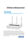
Mi Casa Verde proposes itself to ―bring home automation to the masses‖ and intends to do it
with Vera (Figure 2), a low-budget home-control gateway with Z-Wave support.
Z-Wave is a short-range, low-power, proprietary wireless technology especially designed by
Zensys to implement remote control in home-automation systems. (4)
The Vera gateway is a standard wireless router with a Linux-based firmware, attached to a ZWave USB dongle and running special built-in software. It hosts a user-friendly web interface
with embed tutorial videos, that maintains a virtual model of the house (or the monitored
environment) to which the user can add Z-Wave devices and with which he/she can define
automation rules that the system will use to control the devices‘ functioning. For some
devices (like light-bulbs, dimmers and power plugs), the system can store a max power value
that it will use to estimate local energy consumption; these consumptions are then presented
in the web-interface, giving the user an idea of how much he/she is spending. (5) (6)
This system also provides a remote-control application for Apple‘s iPhone and iPod Touch to
allow real time interaction with the system, without the need for a computer, turning it into
an almost completely stand-alone system. (7)
Ambient Assisted Living System - Local Monitoring Console
5
Figure 2 - Vera home-control gateway
Despite some initial disbelieve from the community on a supposed almost auto-configurable,
super-simple system that ―anyone could set up‖, Vera has gain the public‘s attention and has,
so far, manage to level with the expectations.
Its main advantages are the relatively low price (approx. $300), the easy setup and the
possibility of creating complex scenes and event-driven alerts. As it uses an open-source
Linux-based firmware, it would be possible for a developer to add extra features to the
gateway, even if it would not be possible to improve the MiCasaVerde software itself, since it
is not open-source. As an AAL monitoring console it has a few handicaps, the biggest of which
is the exclusive support of Z-Wave enabled devices, increasing development costs of eventual
new monitoring modules and ―closing the door" to many existing devices and monitoring
applications, namely the health monitoring ones.
3.1.2 W ELLNESS C ONNECTED ™,
BY
A&D M EDICAL
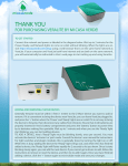
The Wellness Connected combo (Figure 3) from A&D Medical/LifeSource is a health
monitoring solution especially developed to promote self-monitoring. It combines three
wireless-enabled health monitors with a software application that automatically receive,
store and display measurements in graphs with an easy-to-use interface.
The integrated medical devices are a blood pressure monitor, a weight scale and an activity
monitor (measures number of steps, activity times, calories burned, travelled distances and
categorizes each activity as a run or a walk). They all work in a one-button-operation basis
and cache the measures in internal memories that are ―downloaded‖ by the software running
on a personal computer through a special USB radio adapter, whenever the devices are within
range. (8) (9)
A&D Medical offers an optional upgrade service in which data records are uploaded directly to
a web server (there is still the need for a computer and an internet connection), making it
virtually accessible from everywhere and enabling users to track their relatives‘ or friends‘
progress.
Ambient Assisted Living System - Local Monitoring Console
6
Figure 3 - Wellness Connected system
The user-friendliness and ease-of-use of this system makes it a good example of a home
based, personal health monitor, this being its biggest advantage. Also, its Bluetooth-based
wireless connectivity may allow the integration of its monitoring devices with other systems
and networks.
From the AAL point of view, as a complete system/monitoring network this solution is rather
limited, mostly because of its dependence on a computer to collect data, but also because it
does not offer support for any other device and these three alone are often not enough. Also,
this product seams to aim more on the fitness and well-being market than to the clinical
monitoring and diagnosis one.
3.1.3 H OME C ONTROL C ENTER ,
BY
T HERE . C ORPORATION
There. Corporation is a spinoff from Nokia to the home automation and monitoring market.
The company is preparing to launch, in the beginning of 2010, a new home control console
that promises to fulfill the gap between the different systems and technologies, finally
enabling communication between devices that ―speak different languages‖. (10)
The strategy is to develop a standard gateway-based platform, with embed Z-Wave, Wi-Fi,
Ethernet support and open to other wireless technologies, controllable by cell-phone and by
web-interface. This gateway hosts a user-interface capable of controlling not only There.‘s
provided devices but also third-party solutions and systems that extend the system reach and
applicability. (11)
The company plans to launch a first version called ―Safety 360‖ on the beginning of 2010, as a
"security kit" for monitoring fire and water leakage alarms, intrusion detection and energy
consumption. (12)
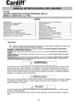
The Home Control Center is presented in Figure 4.
Ambient Assisted Living System - Local Monitoring Console
7
Figure 4 - There.'s Home Control Center
As it is not ready yet, there isn‘t much tangible information on the system‘s real capabilities
and features. As it claims to be a comprehensive solution, able to monitor every ―intelligent‖
system in the house and to integrate all the collected information, it may be appropriate to
implement an AAL system, even if the monitoring of healthcare sensors and devices is not
among the first applications of this system.
Previous descriptions leave the idea that it is not easy to find a standard solution to integrate
information from very different sources. It seems that each application area has developed its
own wireless technology and is doing everything to turn that technology into a wireless de
facto standard instead of investing on integration. It became clear is not possible to develop a
unique control center for networks with different scopes without supporting at least a few
different wireless protocols and bridge the information between the sub-networks.
Another important consideration can be retrieved from the previous analysis. It regards the
importance of including a user-friendly interface in the console to help the user configure the
network and interact with the system.
In this scenario, there is clearly an opportunity for a system able to ―talk different languages‖
and capable of integrating health and clinical monitors with the existing home monitoring
networks and devices.
3.2 I NITIAL I DEA
The biggest challenge in developing an Ambient Assisted Living integrated system is to keep
costs contained and still produce a comprehensive and functional solution, able to arouse the
potential client‘s interest. To answer to this challenge, it is very important that every module
is balanced with the whole, and has itself the lowest possible cost.
The vision that defines this project is therefore to produce a good performance and on the
same time low-cost monitoring console. The chosen strategy was to take a fully developed,
stable and tested commercial platform and, making use of open-source firmware/software,
develop a software solution to handle the monitoring process.
Ambient Assisted Living System - Local Monitoring Console
8
Besides from the economical aspect, there were a few other guidelines to take into account:
1. The console should be flexible, capable of working in different modes and adaptable
to various monitoring situations;
2. It is very important for the console not to be dedicated to a single short-range
wireless protocol/technology;
3. Until the platform‘s real processing capabilities have been properly tested, the
priority should be to maximize the throughput and not the local data processing.
The first task was, then, to identify a solution that would fit these conditions.
3.3 O PPORTUNITY : L INUX & R OUTERS
The story begins in the earlier 2003, with the discovery of Linksys use of GPL code on their
WRT54G wireless router firmware. According to GPL terms, anyone who modifies open code is
required to release his/her modifications back to the community, as so, Linux enthusiasts had
pressured Linksys and the company released its modified code under the GPL. (13)
With the release, also in 2003, of the first firmware customizing tools and some methods of
cross-compiling code for the WRT54G router, the door to third-party firmware for routers had
finally been open, and the number of available firmwares soon grew, and the list of
―hackable‖ devices extended not only to other Linksys routers, but also to other brands. (13)
Searching the web, for discussion forums, wikis and websites on this topic, it is easy to
discover the main purpose of switching the original firmware of a wireless router to a
customized/customizable one add new features and improve its performance. The general
goal is to ―turn a $60 router into a $600 one‖. With that said, and having for a fact that there
is always someone thinking outside the box, it is also not difficult to discover bold projects
were the router‘s role is very far from its original one:
transforming a router into a web server;
adding sensor to monitor temperature;
share internet from a GSM/GPRS USB modem;
create a VoIP server;
adding a monitor and a keyboard — turn it into a computer!
In fact an electronic device with processing capability, static and operating memory, network
interfaces, LEDs, buttons, eventually RS232 and USB ports where virtually any peripheral can
be connected, running a ‗full feature‘ operating system, with the possibility of developing
cross-compiling new applications might well be a computer.
All of that for less than €100, in a book sized box that has a power consumption of less than 7
Watts (approximate). Looks like an appropriate solution for a low-cost monitoring console.
3.4 F IRMWARE S ELECTION
As referred above, the number of third-party firmwares for routers has had a big initial boom,
mostly due to the fact that there were a lot of developers taking Linksys Linux-based code
and customizing it for single purposes.
Ambient Assisted Living System - Local Monitoring Console
9
As a response to this increase of distributions, on January 2004 the recently created
OpenWrt.org project team has released OpenWrt. Their approach was to develop a
GNU/Linux-based core with minimal features that could support the router‘s processor and
network interfaces. It would then be a Debbian-like package management system to give the
user the means to customize each installation to his/her needs. The software development kit
completes the package, allowing the user to develop and cross-compile his/her code. (13)
From 2004 until now, lots of different firmware solutions appeared and were abandoned, lots
of different approaches were explored and the lists of available features have grown.
Nevertheless, almost every one of today‘s available distributions were forked from OpenWrt,
or had at some point adopted its kernel base (DD-WRT) and, from all of them, OpenWrt
continues to be the one more suited for development, since it continues to leave to the user
the decision of what features to include.
Another OpenWrt advantage is its big community of developers and users, which may be a
great help to solve eventual problems during the development phase.
3.5 H ARDWARE S ELECTION
Having selected the firmware, the next step was to select the router, and the first natural
criteria would be its compatibility with the previous.
The other identified criteria would be:
1.
2.
3.
4.
5.
Hardware features (memory and processor);
Market availability;
Support (online forums and communities, books…);
USB connectivity (possibility of using storage and radio dongles);
Price.
Given OpenWrt‘s nature, the hardware requirements strongly depend on the user‘s objective,
as is him who selects which packages/features to include. Even so, and as a reference, for a
standard usage it‘s advisable not to use devices with Flash memory less than 4Mb and RAM
memory less than 16Mb1. (14)
Analyzing the online forums and community sites available on the theme, one gets the feeling
that, apart from the many users trying to enhance the old router they have at home and
maybe get more out of it, the majority of projects involving open-source firmware for routers
use the same three or four devices. By studying the supported hardware list kept on OpenWrt
project‘s website and filtering the units which production has been discontinued and the ones
which the average price is higher than $100, one easy understands why.
The fact is that the latest models and versions tend to be equipped with less memory,
probably in a manufacturers attempt to reduce costs, which makes it hard for a open-source
firmware to fit in and even harder for the user to include new features.
1
It is possible to install OpenWrt in devices with as less as 2Mb Flash and 8Mb RAM, but the
system will only be able to perform very basic operations. (15)
Ambient Assisted Living System - Local Monitoring Console
10
Table 2 presents the most used routers and their main characteristics.
Table 2 - Selected routers main characteristics (15)
Router
CPU
FLASH
RAM
USB
Price
ASUS WL-500Gp v1
MIPS32 - 266MHz
8Mb
32Mb
2x
77€
ASUS WL-500Gp v2
MIPS32 - 240MHz
8Mb
32Mb
2x
71€
Linksys WRT54GL
MIPS32 - 200MHz
4Mb
16Mb
-
60€
Netgear WGR614L
MIPS32 - 240MHz
4Mb
16Mb
-
58$ (amazon.com)
The WRT54G wireless router family has been, for historical reasons, the sand-box of opensource routing firmware development, it is very well documented, there are a lot of tutorials
available online and they have been transformed in almost everything one can think of. It will
not be too risky to affirm that this is probably the most successful router series ever made.
Nevertheless, at one point Linksys tried to reduce costs, and after hardware version 4 of
WRT54G, the memory was reduced and its Linux-based firmware was deprecated for a
proprietary one. The WRT54GL is the open-source version that they decided to keep (and sell
at a higher price) to appeal to the hacker community. (13)
The ASUS WL-500G premium router is a case of success. It is a very powerful router with its
266MHz processor, and its 8Mb Flash and 32Mb RAM are a big trump within this price level.
The USB ports are also a very interesting attribute, since they may allow the easy connection
of peripherals and the expansion of the platform. ASUS has launched a second hardware
version of this router which uses a slightly slower processor and costs also slightly less, which
presented a few issues with OpenWrt compatibility, but that seems to be overcome. The
weak link of this platform is its wireless card, which driver doesn‘t work with Linux kernel 2.6
(there is an open-source driver driver b43 — that may solve the problem, but is not yet
stable). The solution would be the replacement of the wireless card or the use of kernel
version 2.4.
Netgear had an original approach to the subject, they decided to embrace the open-source
community and develop a low-cost, Linux based router compliant with the major third-party
software requirements (it can come with OpenWrt, DD-DRT or Tomato firmware preinstalled), selling it as ―the Open Source Route‖. The WGR614L has a slightly faster processor
than the WRT54GL but doesn‘t bring any advantage when compared to the ASUS; its biggest
trumps would be the ‗official‘ support of open-source firmwares and the lower price, but as it
is not available in Portugal, this last consideration is no longer valid.
The selection of the ASUS WL-500G premium (Figure 5) is easily explained by its superior
characteristics. Given this project experimental nature, and the fact that one would be
exploring a platform on tasks it wasn‘t designed for, it was very important to start with a
solid base, and the larger memory, processing speed and USB connectivity of that device
promised to fit the expectations. As for the hardware version of this router, there were some
doubts on version 2 real compatibility with OpenWrt, and as version 1 was still available the
decision went for this one. The wireless card issue was solved by using Linux kernel 2.4
OpenWrt version.
Ambient Assisted Living System - Local Monitoring Console
11
Figure 5 - The ASUS WL-500G Premium Wireless Broadband Router
Ambient Assisted Living System - Local Monitoring Console
12
C HAPTER 4: S YSTEM ’ S A RCHITECTURE
The monitoring console is, within the different applications, the local concentration module
responsible for the generated signals‘ collection. It aims to be the system‘s local center,
managing short range wireless communications, sending the collected data to a remote server
and/or locally process and store that data.
The console consist on a standard wireless router, of which original Firmware has been
replaced by a specific Linux distribution — OpenWrt. Over this operating system, runs a
software solution that manages the entire monitoring process.
The logical model of the software solution is centered in the concept of a Monitoring
Network, configurable by the user, which comprehends the devices to monitor and their
configuration parameters.
Figure 6 illustrates the concept behind the monitoring console.
Figure 6 - Monitoring console’s conceptual scheme
System‘s present version only uses Bluetooth communication protocol and the devices must
be configured to either send the data to a remote server or store them locally.
Ambient Assisted Living System - Local Monitoring Console
13
4.1 S YSTEM F EATURES & R EQUIREMENTS
4.1.1 H ARDWARE
The present version of the monitoring console uses the following devices:
1. ASUS WL-500G premium Broadband Wireless Router;
2. SWEEX BT211 Bluetooth Adapter;
3. USB storage device (―Pen‖).
This section presents a description of these components and the requirements in which their
selection was made.
4.1.1.1 THE ROUTER
As stated in section 3.5, the selected router has been the ASUS Wl-500G premium. The
arguments on which the selection was made had also been described.
Since the goal was to use an existing platform without altering its hardware (at least as a first
approach), no deep hardware study done. Nevertheless, the platform features are presented
in Table 3.
Table 3 - ASUS WL-500Gp hardware features (16)
CONNECTIVITY
MEMORY
PROCESSOR
Architecture
Vendor
MIPS
Broadcom
Bootloader
CFE
System-OnChip
Broadcom BCM94704
CPU Speed
266 Mhz
Flash size
8MiB (Spansion S29GL064M90)
RAM
32MiB (2* HY50U281622ETP-5, some older units have
only 16MiB enabled)
Wireless
MiniPCI Broadcom 802.11b/g
Wireless LAN Controller
Ethernet
Robo switch BCM5325
USB
BCM4318
802.11
2x USB 2.0
Serial
Yes
JTAG
No
The router is in fact the key part of the puzzle, and the requirements for it were simply to
have a relatively fast processor (not comparing it to a real computer, of course), enough
memory for software development, and high connectivity and/or expansibility.
Ambient Assisted Living System - Local Monitoring Console
14
4.1.1.2 THE BLUETOOTH ADAPTER
The Bluetooth devices have two classifications, the Class and the protocol version. The Class
of a Bluetooth device defines the power of its radio and consequently its range, as described
in Table 4.
Table 4 - Bluetooth Class features (17)
MAXIMUM PERMITTED POWER
(MW / DBM)
APPROXIMATE RANGE
Class 1
100mW / 20dBm
~100m
Class 2
2.5mW / 4dBm
~10m
Class 3
1mW / 0dbm
~1m
CLASS
The Bluetooth protocol version identifies the different phases in this technology evolution
path. Apart from the addition of new features, that evolution has brought successive
increases on the data-transfer rate and the last version (2.0 with EDR) can reach speeds of
3Mbit/s.
The main concerns about the adapter to use are that it should not create a bottle-neck in the
communications and it should be compatible with Linux‘s Bluetooth Stack BlueZ. On the
other hand, its price should be as low as possible.
The selected adapter, the SWEEX BT211, is a Class 1, Bluetooth 2.0 with EDR adapter with a
retail price of less than 10€. As for the BlueZ compatibility, it is not very common for a
manufacturer to ensure Linux operating systems compatibility to his products, so the only way
to check this was by testing it, and it worked.
4.1.1.3 THE USB STORAGE DEVICE
The USB storage device should have enough memory to store at least the information
generated during one monitoring session. The total amount of information has not been
defined and will depend on the monitoring devices‘ number, their sample rate, the data
package size generated by each one and the duration of a ―monitoring session‖. 2
Another concern is that large memory storage devices, may require external power supply,
and that may not be desirable.
4.1.1.4 THE SUPPORTED DEVICES
As the console development depends also on the devices it is supposed to monitor, this subsection is meant to describe in general those devices and their function.
4.1.1.4.1 BIOPLUX
Bioplux is a wireless enabled, miniaturized signal acquisition system especially designed to
acquire electrophysiological signals. It provides up to 8 analog channels and one digital I/O
port, allowing the monitoring up to 6 variables, using the provided sensor set. It uses the
2
As an example, to store the entire data-string generated by an iMeterPlug‘s [4.1.1.4.3] live
measurement (approx. 550 bytes) at a frequency of 1Hz, one 1 GB device would be enough
for about 21 days.
Ambient Assisted Living System - Local Monitoring Console
15
Bluetooth protocol to send the raw, digitalized data to a computer. The 8 channel, research
version is displayed in Figure 7.
Figure 7 - Bioplux Mini Research
The list of sensors supported by this device includes peripheral thermometer, EMG dipole
probes, light sensors, ECG triode, Electrodermal sensors or air pressure sensors. This amount
of different sensors definitely contributes to Bioplux‘s versatility and increases the usage
possibilities.
Despite of this project‘s implementation of Bioplux protocol is independent of the data type
(what the console receives are just numbers), the main intention of using this device was to
take advantage of its ECG sensors.
The Electrocardiographic signal is by many considered the first and eventually most important
signal in vital signs monitoring. It consists of a trans-thoracic interpretation of the heart‘s
electrical activity. (18) The signal is obtained by measuring the electrical potential difference
between the different electrodes placed on the patient‘s chest (in this case, since Bioplux has
only a 3 channel ECG). It is in general a very important tool to diagnose both acute and
chronic cardiac conditions.
4.1.1.4.2 OXIMETER
A pulse oximeter is a device that performs non-invasive, indirect measures of blood‘s oxygen
saturation. It can also monitor the patient‘s heart rate and perform photoplethysmographic
studies of skin‘s blood volume. (19)
The O2 saturation is calculated from the relative percentage of oxyhemoglobin in the arterial
blood‘s hemoglobin. It uses a set of two light sources with defined wave-lenghts (red at
660nm and infrared at 905, 910 or 940 nm) and a photodiode that measures the light
absorption. As oxyhemoglobin and deoxyhemoglobin light absorptions, at these wave lengths,
are very different, their relative concentrations can be calculated and, consequently, also the
SpO2. (19)
This simplicity and speed of these devices make them extremely important in emergency
medicine and for monitoring patient with respiratory or cardiac conditions, including the
diagnosis of some diseases (sleep apnea, for example). (19)
NONIN‘s 4100 Digital Pulse Oximeter allows SpO2, heart rate, and plethysmographic data to be
transmitted wirelessly through a Bluetooth radio to a Bluetooth-enabled device. (20) It can
function in different modes, allowing continuous monitoring as well as configurable spotchecks, with sample rates of 1Hz or 75Hz and different resolutions.
Ambient Assisted Living System - Local Monitoring Console
16
Figure 8 shows this device.
Figure 8 - NONIN 4100 digital pulse oximeter
4.1.1.4.3 IMETERPLUG
iMeterPlug is an electrical Energy consumption monitor, and it is included in this project as an
example of how the Ambient Assisted Living comprehends not only the monitoring of
individuals‘ vital physiological information, but also of his/her environment, especially the
home.
As its name suggests, iMeterPlug is a device that can be placed in an electrical plug and
measures the electricity consumption of device(s) to it attached. Figure 9 shows ISA‘s
iMeterPlug.
Figure 9 - ISA's iMeterPlug
From the moment it is connected to a plug, the iMeterPlug starts monitoring. It has an
internal circular log to which it saves records in configurable periods of time (resolution: 1
minute); the user can then download these records using the Bluetooth RFCOMM profile.
iMeterPlug does not have a mode for continuous monitoring, but its protocol have a command
(‗LV‘) to which the device respond with a live measure, and one can use this command to get
a more frequent sampling (this project‘s implementation manage to get a sampling rate of
nearly 1Hz).
The available data fields are:
1. Time entry;
2. Power (-Gen +Con);
Ambient Assisted Living System - Local Monitoring Console
17
3.
4.
5.
6.
7.
8.
9.
10.
11.
12.
13.
Cumulative Power (Gen);
Cumulative Power (Con);
Frequency;
RMS Voltage;
RMS Current;
Plogg on time;
Reactive Power (-G/+C);
Acc Reactive Pwr (Gen);
Acc Reactive Pwr (Con);
Phase Angle (V/I);
Equipment on time;
The user can configure which of these fields should be stored in automatic records, but ―live
measures‖ can‘t be configured and return all of the fields. ISA‘s protocol for this device only
requires the storage of:
1.
2.
4.
9.
11.
Time entry;
Power (-Gen +Con);
Cumulative Power (Con);
Reactive Power (-G/+C);
Acc Reactive Pwr (Con);
As so, and in order to get high sample rates, the strategy to follow should then be to
continuously request live measures to the iMeterPlug and then parse the data frame for the
information to store.
4.1.2 S OFTWARE
The software is what turns the ordinary wireless router into a monitoring console. Its mission
is to manage the entire monitoring process, from the monitoring network‘s management
(device adding and configuring) to the actual data acquisition and processing.
As said before, the developed software runs over a special Linux-based firmware program
OpenWrt. This means that, from the programmer‘s point of view, it is not necessary to test
and release the entire firmware when developing an application, allowing him/her to
concentrate on the application itself. (21)
Given the router‘s reduced memory space, it was not possible for OpenWrt developers to
include standard GNU Compiler Collection (GCC), GNU C Library (glibc) or GNU C++ Library
(glibc++). As so, OpenWrt standard images come with uClibc installed, which is a C library for
embedded Linux systems, much smaller than the glibc, but that supports nearly all
applications developed with this library. uClibc++ is also provided, but as an optional
package. The compilation issue couldn‘t be solved this way, the only option was to create a
cross-compilation mechanism and compile the applications in another system, installing the
executable files afterwards.
OpenWrt can then be seen as a development platform, and it comes with a Software
Development Kit (SDK) that contains the appropriate libraries and cross-compilers for the user
to create installable packages with his/her applications.
Ambient Assisted Living System - Local Monitoring Console
18
The SDK is a stripped-down version of the OpenWrt build system, which can build packages
using the same package directory format as the full Buildroot. (21) The package creation is
mediated by GNU‘s ‗make‘ tool and user defined make-files.
In this project all applications were written using C programming language. This allowed not
to install the C++ library and to save some space. The decision do not translate any
compromise on functionality as C is a very powerful programming language and is perfectly
suited to the development of these kind of applications.
C is one of the most important programming languages ever developed. It was originally
designed for the UNIX operating system, and has been ever since mostly used for system
software implementation (operating systems, compilers, other languages…). It is used in a
very wide set of platforms, and on almost every computer architecture, mostly because of
the relatively easiness of creating a C compiler for a specific architecture. It is also widely
employed on writing application programs. (22) (23)
C‘s success is much due to its minimalistic design that gives it simplicity, efficiency,
flexibility and small memory requirements. Programs written in C are also highly portable, as
the C compilers and libraries are available for numerous platforms.
Despite being a high-level language (as its syntax is closer to standard English than to machine
language), it is often considered as lower-level when compared to other programming
languages as it provides a set of low-level features (direct memory access, for example).
4.1.2.1 WEB INTERFACE
The scope of a web interface inclusion is to provide users with a friendlier way to configure a
monitoring network (relatively to manual edition of config files) and avoid errors. By
configure it is meant adding and removing devices to and from the network, and setting each
device monitoring parameters.
The interface also displays network current content.
4.1.2.2 MONITORING SOFTWARE
The monitoring modules are the system‘s functional blocks. They need to handle the
Bluetooth connections, to implement each device communication protocol, collect the data,
process the received packages and send/store the information.
4.1.3 S HORT R ANGE C OMMUNICATION P ROTOCOLS
Despite the earlier intention of creating an open platform, capable of supporting a wide range
of communication protocols, the monitoring devices available all used Bluetooth. As so, and
for this first version, only Bluetooth is supported.
4.1.3.1 BLUETOOTH
Bluetooth is likely to be the most popular WPAN creation technology. It is an unlicensed
wireless radio technology, designed for low-power, short-range data exchange between
electronic devices. (17) (24) It was first created with the intention of replacing serial cabled
Ambient Assisted Living System - Local Monitoring Console
19
connections, but its field of applications has became wider, and now Bluetooth stands as an
alternative to almost every cabled connection.
Bluetooth‘s biggest advantage is in fact its price. It starts for being an open technology, not
requiring the payment of licenses and/or royalties of any kind; second, it uses low-cost
transceiver micro-chips on its radios making them very cheap for mass-production; third, as it
keeps transmission power at very low levels, it is a great option for battery powered devices.
For ensuring safety in data transmission, Bluetooth offers optional encryption in device
connections. For the user, this encryption takes the form of the PIN, which is used to
generate the encryption-key and if not equal in the two devices, connecting will not be
possible.
Ambient Assisted Living System - Local Monitoring Console
20
C HAPTER 5: S OFTWARE D EVELOPMENT
The software solution includes a web interface that edit the files that contain the network
device‘s configuration, one application that reads those files and starts the monitoring
process, and a set of pairs of applications that, for each device, establish the Bluetooth
connection and collect the data (receiveBioplux, receivePlogg), and take care of the
processing, storing and transmission of the information (processBioplux, processPlogg).
Figure 10 is a diagram of how these modules relate to each other.
sistem
boot
mntrcnsl
config.
files
read
edit
Web Interface
start
process
output
output
processBioplux
processPlogg
IPC
receiveBioplux
input
receivePlogg #1
input
receivePlogg #2
input
IPC
…
…
Figure 10 - Software solution’s general architecture
Because a transmission protocol to send the collected data to an external server has not yet
been design, in this system‘s current version, the processing applications do not support this
feature. As so, it was decided the integration on the final prototype (Prototype #1) of the
demonstration modules demoBioplux, demoOx and demoPlogg that collect and transmit the
date directly from the devices to visualization applications in remote computers.
The inclusion of these applications has the purpose of demonstrating the system‘s capability
of transmitting data collected in real time from a device to a remote system, at the same
time that it locally stores data from another device. It was also a way of testing the
developed web interface.
To complete the previous scheme, the blocks in Figure 11 should be added.
Ambient Assisted Living System - Local Monitoring Console
21
…
…
output
demoBioplux
input
output
demoOx
input
output
demoPlogg
input
…
Figure 11 - Demonstration modules used for direct transmission of the data
5.1 W EB I NTERFACE
The web interface has been developed using HTML and CSS languages. Its design is optimized
to be displayed with Microsoft‘s Internet Explorer 7 and Mozilla Firefox 3 web browsers, and
with screens with a minimum resolution of 800x600 pixels.
The HTML forms processing is done using CGI programs. CGI is an acronym for Common
Gateway Interface which is a standard protocol for interfacing external application software
with an information server, commonly a web server. (25) These applications can be written in
any programming language, and in the current case C programming language was used.
All the forms use the POST method to collect input data.
5.1.1 L AYOUT
AND
O RGANIZATION
The interface‘s layout was structured in four different visual areas that stand from a textured
blue background. On top, a white horizontal bar holds ISA‘s logo and creates a visual
connection to the company and beneath it there is a black navigation bar. On the left,
superimposed to the first two, lies a red, semi-transparent vertical menu bar that displays
buttons that link with the interface‘s main areas & tools. The content is displayed in a white,
expandable rectangle on left-right corner. [Annex A: Web interface main page]
The design was meant to be simple and intuitive, and was based on ISA‘s image color scheme.
5.1.1.1 SITE MAP
The web site is organized in three sections, the ―Add Device‖ tool and the ―My Health‖ and
―My Home‖ network display areas. Within these last two areas there is also a division by
device type.
The conceptual organization of the website is shown in Figure 12. The arrows intend to
express form processing
Ambient Assisted Living System - Local Monitoring Console
22
addDevice.htm
addBioplux.htm
addBioplux.cgi
addOximeter.htm
addOximeter.cgi
addiMeterPlug.htm
addiMeterPlug.cgi
scan.cgi
addScan.cgi
addSingleDev.cgi
my Health
biopluxs.cgi
oximeters.cgi
removeDev.cgi
my Home
imeterplugs.cgi
Figure 12 - Web Interface site-map
5.1.2 HTML
FORMS
& CGI
PROGRAMS
As this web interface‘s scope is to display, add and remove devices to/from the monitoring
network, mainly every one of the web pages have a HTML form.
Adding a new device to the network typically involves a webpage with an HTML form, and a
CGI program to process it. The output of the process is a new line in the devices configuration
file. These forms are organized by information type, in two or three areas:
1. Device identification Bluetooth communication parameters;
2. Monitoring parameters (just for Bioplux);
3. Data handling information.
The program reads the data from standard input and stores them as structured text, in
configuration files. [Annex B: Configuration files‘ structuring]
The CGI applications that display the network access these files, parse them and structurally
print the devices‘ configuration information into a web page.
Ambient Assisted Living System - Local Monitoring Console
23
5.1.2.1 ADD DEVICE FROM SCAN
Other than being a more user-friendly method of configuring the monitoring network, the web
interface offers another advantage relatively to the manual edition of the configuration files.
It has an application that scans for nearby devices, presenting a list of MAC addresses and ID‘s
for the user to choose from. This feature may prevent the need to know the Bluetooth MAC
address in advance (since it is normally not visible) and the need to insert it manually.
The flowchart of this procedure is presented in Figure 13.
The three different CGI programs involved in the process are:
1. scan.cgi, that performs the scan and presents a list of nearby devices to the user (its
output is presented in Annex C:);
2. addScan.cgi, which displays the selected device‘s name and MAC address and asks for
the type of device;
3. addSingleDev.cgi, that presents an input form and collects monitoring and data
handling parameters.
“go Back”
perform an
„inquiry‟
n
select a device
answers?
confirm the
selected ID and
address
y
define the type of
device
get names and
addresses
“Continue”
fullfill monitoring
parameters
print table with
name, address
and an „Add‟ form
print “no devices
in range”
fullfill data
handling
parameters
“manual”
procedure
“Add”
confirmation
re-scan
scan.cgi
addScan.cgi
addSingleDev.cgi
Figure 13 - Adding nearby devices procedure using the 'scan' tool
Ambient Assisted Living System - Local Monitoring Console
24
5.2 M ONITORING M ODULES
5.2.1 M ONITORING S ESSION B OOT –
MNTRCNSLD
This application works as a bridge between the user‘s instructions and the monitoring
modules. It is started by the system‘s boot and loads the other applications, passing them the
parameters defined in the configuration files.
Its architecture consists of three main functions called sequentially — startBiopluxs,
startOximeters, startPloggs. Figure 14 represents the general flowchart for these functions.
open config file
return
n
file exists?
y
start „receiveDevice‟
application
read line
y
EOF?
start „deviceDemo‟
application
start „processDevice‟
application
n
y
check parameters
y
action = „send‟?
n
„processDevice‟ has
been started?
n
*not yet implemented for the Oximeter
Figure 14 - mntrcnsls main function's flowchart
For the oximeter there is only the demonstration application (that doesn‘t support the local
storage of data), so startOximeters only starts the monitoring of devices configured in
‗sending‘ mode.
5.2.2 D ATA P ROCESSING
This group of applications is responsible for the creation of the Interprocess Communication
(IPC) mechanism — System V Message Queues (MQ), in this case — and for the structured
storage of the collected data in the USB storage device.
Despite the existence of one data collecting application for each individual device, there is
only one process running the data processing application for each device type, and all of
those processes use the same MQ. The processing uses the message‘s label (msg_ID) to
Ambient Assisted Living System - Local Monitoring Console
25
separate data from different sources. As the label needs to be a long integer (System V
Message Queue‘s requirement) it is created from the device‘s line, on the configuration file.
The general flowchart of this type of applications is represented in Figure 15.
create storage
folder
DISCONNECTED
create
message
queue
created
failed
WAITING
n
message?
FAILURE
n
terminating
signal?
y
return
y
n
get message
correct size?
y
check file
descriptor
incorrect
correct
(re)open file
*just for processBioplux
print time
n
„time‟ field = 1?
y
print data record
Figure 15 - Processing applications flowchart
The application uses a variable to store the label from the last received message and a file
descriptor that points to that msg_ID‘s corresponding file. Whenever the label from an
incoming message is different from the stored one, the file descriptor is redirected to the
correct file.
5.2.2.1 PROCESSBIOPLUX
Bioplux‘s data message structure is the following:
struct parsedData {
long msg_ID;
char bp_ID[30];
unsigned char frnumber;
Ambient Assisted Living System - Local Monitoring Console
26
unsigned char digitalPort;
short chValue[8];
time_t time;
};
The packages sent by the Bioplux contain sequential measurements of the fisical/fisiological
parameters that should be organized by session, defined as an uninterrupted record
sequence. In order to store more than one session in the same file, every time a connection
with the device is established, the system generates a ‗date & time‘ message that is then
printed to the file, separating records from different sessions. This is ‗time‘ field‘s scope — in
the data structure and in ―normal‖ messages this field is set to 1. The ‗date & time‘ line has
the following shape:
Bioplux ‘X’
time(): Y
X is the internal ID of the Bioplux (defined during configuration) and Y a time_t integer
representing system‘s date and time at the beginning of the session.
The records are stored as lines with the digital port value in first place, followed by the eight
analogical channel values. The separation is made with ‗tabs‘.
5.2.2.2 PROCESSPLOGG
iMeterPlug‘s data records are created with lower frequency and every record has a timestamp
of its own with the device‘s date/time of creation. Consequently, there is no need to split the
file in sessions.
The structure of the incoming message is:
struct parsedData {
long msg_ID;
char plgg_ID[30];
char timestamp;
float plogg[4];
};
Table 5 shows the information stored in ‗plogg‘ array.
Table 5 - iMeterPlug's stored data
plogg[0]
Power
plogg[1]
Consumed Energy
plogg[2]
Reactive Power
plogg[3]
Consumed Reactive Energy
In the file, the records are stored as lines and the information is sequenced as: timestamp >
plogg[0] > plogg[1] > plogg[2] > plogg[3], with ―tab‖ separation.
5.2.3 D ATA C OLLECTION
AND
P ARSING
This application group is responsible for the establishment and management of the Bluetooth
connections, the implementation of the communication protocols of each supported device,
Ambient Assisted Living System - Local Monitoring Console
27
the collection and parsing of the data frames. The parsed information is passed to the
processing applications through the different message queues.
5.2.3.1 RECEIVEBIOPLUX
This application takes, as input, a long integer to identify the outgoing messages (msg_ID),
the name/ID of the device, its MAC address and Bluetooth PIN. The generated messages
structure is the one described for the processBioplux application.
Within the application, there is a Finite State Machine (FSM) mechanism that interchanges
between NOT_CONNECTED, CONNECTED, PREPARED, ACQUIRING, ACQ_LAST and FAILURE
states. This states where defined after the second version of Bioplux‘s communication
protocol. The flowchart of this FSM is the one in Figure 16.
NOT_CONNECTED state is the one in which there is no established connection and, if no
terminating signal has been received, in which the system tries to create a Bluetooth
connection with the device, using RFCOMM protocol.
If a connection exists, the application switches into CONNECTED mode and the following
action is sending a preparation command, requiring for a confirmation of the device‘s
firmware version that, if received, takes the application into PREPARED state. If this action is
unsuccessful the system closes the connection and returns to the initial state.
In PREPARED mode, a Start Message is created and sent to the device, containing the channel
bitmask, sample rate and resolution that shall be use for the monitoring session. This
information is defined in the configuration files and is given to the application as input. As an
answer to this message, Bioplux starts collecting data and the application changes into
ACQUIRING mode.
In acquisition mode, packages are received and pre-processed into structured messages that
are put in the MQ created by the processBioplux. The application continues to work in this
mode until a signal is received or an error occurs.
Telling the device to stop acquiring data is done by sending a ‗terminating command‘.
Because there is always some delay between sending a command and its reception, it is
normal that a few packages may yet to be received in the socket buffer, so the system shall
switch into ACQ_MODE to collect these last packages, and then re-send another request for
the firmware version to confirm the reception of all the packages.
FAILURE mode results from an error in the package parsing function. Every other error
situation makes the application to disconnect and restart the process.
Ambient Assisted Living System - Local Monitoring Console
28
NOT_CONNECTED
y
return 0
terminating signal?
n
connectBioplux()
failure
success
failure
success
timeout
success
receiveFrame()
CONNECTED
requestFWversion()
endAcqMode()
failure
success
ACQ_LAST
PREPARED
terminating signal?
y
return -1
n
failure
startAcqMode()
success
success
failure
FAILURE
failure
endAcqMode()
success
ACQUIRING
y
timeout
receiveFrame()
n
terminating signal?
Figure 16 - receiveBioplux's FSM flowchart
Bluetooth communications with Bioplux are encrypted and, as so, before establishing a
connection there is the need to change the console‘s Bluetooth PIN to match the devices. In
order to achieve do so, this application, before starting the described protocol, changes
system variable ―pin‖ and restarts the application that controls HCI protocol (the lowest
within the overall Bluetooth protocol).
Ambient Assisted Living System - Local Monitoring Console
29
5.2.3.2 RECEIVEPLOGG
iMeterPlug‘s (or ―Plogg‘s‖) protocol offers a few possibilities for remote systems to collect
data from these devices. Because the initial goal was to maximize throughput, to test the
router‘s capabilities, it was decided to use recurrently ‗LV‘ command, which asks the device
for one measurement. This method enables sample rates of about 1 Hertz. The ―sleep()‖
function called after receiving one package allows this frequency to be decreased.
The application also works with a FSM, but with only two states: NOT_CONNECTED and
CONNECTED.
From the received data string, the system collects the timestamp and the information in
Table 5. With this data fields a message is created and sent to the process running the
processing application.
Figure 17 displays this application‘s FSM flowchart.
return
y
terminating
signal?
NOT_CONNECTED
success
n
connect()
CONNECTED
failure
y
disconnect
terminating
signal?
sendRequest()
n
failure
failure
receivePackage()
success
parsePackage()
sleep
success
failure
transmitData()
0
Figure 17 - receivePlogg's FSM flowchart
5.2.4 D EMONSTRATION A PPLICATIONS
This group of applications has been developed merely for the demonstration prototype. The
aim of this prototyped was (as described above) to collect live data from the devices and
transmit it via Ethernet or Wi-Fi to a computer. Collected data should then be displayed in a
set of graphical interfaces.
Ambient Assisted Living System - Local Monitoring Console
30
5.2.4.1 OXDEMO
This application has the particularity of not performing any kind of pre-processing over the
received data packages. These are transmitted exactly as received, a single byte at a time to
the remote server.
The flowchart of this application‘s FSM is shown in Figure 18.
After successfully establishing a connection with the device, the system tries to connect with
the remote server, when that occurs a start command is sent to the Oximeter and the process
shifts into Acquisition/Transmission state. In this state, the system receives a single byte at a
time from the device and sends it to the server; this cycle is broken when a ‗terminating
signal‘ is received or when one of the peers closes connection. In case of failure, application
shuts down.
The Oximeter, as the Bioplux, uses encryption in Bluetooth communications and this
application also changes console‘s Bluetooth PIN to match the device‘s when trying to
connect to it.
NOT_CONNECTED
failure
failure
n
terminating
signal?
connect with
device
success
success
connect with
server
CONNECTED
y
y
return 0
terminating
signal?
n
y
terminating
signal?
success
ACQ_TR
n
send start
command
failure
success
received no bytes
receive data
received 1 byte
send data
error
y
device closed
connection?
failure
n
FAILURE
y
server closed
connection?
n
return -1
Figure 18 – oxDemo’s FSM flowchart
Ambient Assisted Living System - Local Monitoring Console
31
5.2.4.2 BIOPLUXDEMO
This application has been developed from receiveBioplux and is similar to this one except on
the destiny given to pre-processed data and on the transition between NOT_CONNECTED and
CONNECTED states.
In this case, data is sent through a TCP/IP socket to a remote server with which the
application tries to connect after successfully connecting with Bioplux. If it is not possible to
connect with the server, Bluetooth connection is closed and the process restarted.
In this scenario, as data is destined to live presentation, there is no need to separate non
sequential data (the application on the remote system will do it) and, as so, the ‗time‘ is
dropped from the output data structure as well as the ‗msg_ID‘ label (it is no longer a
message queue, and there is only one source transmitting through the socket).
5.2.4.3 PLOGGDEMO
In this case, and contrarily to the other devices, the graphical interface already existed and
the application needed to be built accordingly to its requirements.
This graphical interface was first meant to directly connect with the iMeterPlug, sending it
commands and collecting readings. As it was not desirable to re-build the entire interface,
and the option was to change it as least as possible, it was decided to build the application to
work as a bridge between the remote system and the iMeterPlug, re-transmitting the
commands and the data from one side to the other, without processing.
The decision‘s main consequences were that the only change that needed to be made in the
graphical interface was switching the Bluetooth socket by a TCP/IP one, and that the new
application couldn‘t use the same structure/mechanist as receivePlogg.
The plan has been to build a FSM with two main working states for the application to switch
during the monitoring session: TR_COMMAND and TR_DATA.
TR_COMMAND is the state when the console is transmitting remote system‘s commands to the
iMeterPlug and TR_DATA the one when data is being transmitted from this device to the
remote system. Transmission is made a byte at a time, and the switching between states is
triggered by timeout mechanisms.
Another difference between this and the other demonstration applications is that it needs to
work as a server and wait for the remote system to connect.
Figure 19 presents the flowchart of ploggDemo‘s FSM.
Ambient Assisted Living System - Local Monitoring Console
32
return -1
create TCP/IP
socket
skip into „listening‟
mode
FAILURE
NOT_CONNECTED
terminating
signal?
return 0
y
n
n
y
failure
interrupting
signal?
connect with
device
y
success
WAITING
terminating
signal?
set tm_count=0
success
n
failure
accept TCP/IP
connection
return 0
n
y
y
timeout?
terminating
signal?
TR_COMMAND
n
failure
closed
connection
success
success
receive data
set tm_count=0
failure
y
send comand
tm_count > 4?
n
n
failure
y
tm_count > 4?
send data
set tm_count=0
success
success
receive
comand
closed
connection
failure
n
y
terminating
signal?
y
TR_DATA
timeout?
n
return 0
Figure 19 - ploggDemo's FSM flowchart
Ambient Assisted Living System - Local Monitoring Console
33
C HAPTER 6: P ROTOTYPING AND T ESTING
6.1 P ROTOTYPES
There have been set two different prototypes with different scopes during the project.
Prototype number one is, in a way, the final result of the project. It was configured as a
demonstration of all that has been developed during the project and of all the functionalities
already implemented. It was also used to test the system.
Prototype number 2 was developed first than the previous. Its scope was to be a quick
demonstration of the AAL Monitoring Console‘s concept.
6.1.1 P ROTOTYPE #1
This is the AAL monitoring console prototype, version 1. Its conceptual scheme is the one
described in Chapter 5: Software Development, Figure 10 and Figure 11.
It uses the same router that has been used as a sandbox to develop and test all the software
as well as to test OpenWrt itself. This router has been reset and re-configured in order to
remove all the obsolete files and install the latest versions of the monitoring modules, proper
configuration files, the web interface and the mntrcnsls application. Table 6 presents the
steps followed to configure this prototype.
Table 6 - Prototype #1 setting
Step
Action
Obs.
1
Re-flash of OpenWrt;
Reset to the standard configuration;
2
Time Synchro;
Add an NTP client and set the appropriate time
zone – this is necessary because the router has no
hardware clock;
3
Add USB support;
Install OpenWrt provided packages;
4
Add USB storage support;
Install packages to support storage through USB
and to support FAT file systems;
5
Create an automount shell script
for the storage devices;
It should analyze the devices that are connect via
USB and, if one is of the storage type, mount it to
/mnt folder;
It should be started at boot;
6
Add Bluetooth support;
BlueZ packages;
7
Install the monitoring modules;
8
Install the mntrcnsls application;
9
Set the system to start mntrcnsls
at boot;
It should be last process to be started by init;
10
Install the web interface;
It should be placed in the /www folder;
11
Create /usr/mynetwork folder;
This is where the configuration files will be
stored.
Ambient Assisted Living System - Local Monitoring Console
34
6.1.2 P ROTOTYPE #2
The development of a demonstration prototype started as a parallel task during the
development phase, while the communication modules were being developed.
For its first version, the requirements were that it should collect real-time data from the
oximeter and transmit them via Wi-Fi to a laptop, were they would be displayed in specific
graphical interface. As at the time, router #1 was being used as a sand box to develop the
communication modules, it was an opportunity to install OpenWrt in a new router from the
beginning and configure it for an exact purpose. A first version of the application oxDemo was
also developed specifically to this prototype. At the time oxDemo received a single input field
with a filename on which it read the parameters, this was changed later on.
Table 7 shows the steps that were followed when setting this prototype.
Table 7 - Creation of the demonstration prototype
Step
Action
Obs.
1
Flash of the OpenWrt
Original firmware replacement.
2
Time Synchro
Add an NTP client and set the appropriate time
zone;
3
Add USB support
Install OpenWrt provided packages;
4
Add Bluetooth support
BlueZ packages;
5
Install the oxDemo application
6
Set the system to always
attribute a known IP address to
the designated laptop.
Add a rule to iptables with the chosen IP address
and the laptop‘s MAC adress
7
Set the system to start oxDemo
on boot;
with the oximeter and server parameters
Support for other devices was included in subsequent versions, through the creation of
Bioplux‘s and iMeterPlug‘s demonstration applications, following the same strategy as for the
oximeter.
With the web interface‘s creation, and the modifications on the parameter passing
mechanism, the prototype was once more altered and it became structurally similar to
prototype #1, with the exception that it only has the demonstration modules and the network
is configured with the demonstration devices parameters and to send the data to the
specified laptop.
6.2 P ERFORMED T ESTS
The system‘s testing was done in two separate moments, with two different objectives. In a
first moment, the web interface was tested to verify its capability of correctly produce and
handle the configuration files. The tests focused on the addition and removal of devices from
the network and were held immediately after the creation of the web interface.
Ambient Assisted Living System - Local Monitoring Console
35
On a second moment, after the development phase finish, the system was tested as a whole
and the focus was set on the user-friendliness of the web interface and the network
configuring process, as well as on the unroll of the monitoring process.
Despite the above, in this section, tests are split into tests on the Web interface and tests on
the monitoring process.
6.2.1 W EB I NTERFACE T ESTING
The intention of including a web interface on this system was, as described on section
4.1.2.1, to create a friendlier way to configure the network and to avoid errors on the
configuring files. As so, when testing it, one of the objectives was to see if its reading/writing
operations introduced, or not, errors in the configuration files.
6.2.1.1 ADDING A DEVICE TO THE NETWORK
Table 8 presents the results from testing the adding devices mechanism.
Table 8 - Test 1: adding a device to the network
DEVICE
TEST
RESULT
OBS
All
All fields filled
ok
‗IP‘ and ‗Port‘ fields are accepted
even when ‗STORE‘ is selected;
All
name unfilled;
mac unfilled;
ok
An error is issued (empty field);
No information is stored on file;
Bioplux,
Oximeter
pin unfilled;
ok
Stored as ‗-‗
Bioplux
No channel selected (bitmask)
failed
A device is added with
'bitmask=00000000';
It would be better to notify the
user;
Bioplux
srate unfilled;
ok
An error is issued (empty field);
No information is stored on file;
All
ip_x empty - STORE selected;
ip empty - STORE selected;
port empty - STORE selected;
ok*
Not detected;
These values will not be used, so
it shall not be a problem;
All
ip_x empty - SEND selected;
ip empty - SEND selected;
port empty - SEND selected;
ok
An error is issued (empty field);
No information is stored on file;
All
Invalid characters (letters in
numeric fields, special
character…) [mac, pin, srate, ip
e port]
failed
There is no validation of the type
of data;
There should be noted that the system does not assume the insertion of an IP address and/or
TCP port as an error when ‗Store‘ is selected because in this case, those values will not be
used. Another notice should be pointed on the fact that ‗Store‘ is not yet available for the
oximeter, and the system doesn‘t notify the user for that fact.
Ambient Assisted Living System - Local Monitoring Console
36
6.2.1.2 DISPLAYING THE NETWORK‘S CONTENT
When one presses ‗Biopluxs‘, ‗Oximeters‘ or ‗iMeterPlugs‘ buttons on the menu, the system
searches for the correspondent configuration files at /usr/mynetwork/. If these files don‘t
exist, or are empty, the system will return a message informing the user that currently there
isn‘t any device of that kind configured in the network. Unless configuration files get
corrupted 3 , there shouldn‘t be any errors associated with the display of the network‘s
content.
6.2.1.3 REMOVING A DEVICE
The removal of a device from the network is achieved simply by clicking the associated
‗Remove‘ button on the display page. By analyzing the underlying mechanism, there should
be no errors associated with this action and, during testing, no errors were ever been
identified.
6.2.1.4 TESTING THE USER EXPERIENCE
The second series of tests were destined to verify the network configuration process, and how
user-friendly the web-interface is. These tests were done by a third-party, with no previous
knowledge of the system and using only the provided user-manual.
As the tester was not familiar with the Bluetooth technology and with the monitoring devices,
he experienced some difficulties to understand the configuration procedures, namely
Bioplux‘s monitoring options, the Bluetooth PIN and the difference between ―send‖ and
―store‖ data-handling actions.
The tester‘s analysis identified, from the user‘s point of view, a few liabilities on the web
interface:
1. The devices‘ Bluetooth user-friendly names [in Annex C: scan.cgi application‘s output]
are often inexpressive and difficult to associate with the actual device, making it
hard for the user to choose the correct device from the list;
2. The system does not verify if the actual device-type matches the user-specified one;
3. The system also does not offer any kind of validation for the input fields, not alerting
the user to eventual inaccuracies.
4. The configurations errors are especially relevant since there is no feedback on the
system performance other than the produced output and the connection
establishment with the devices.
The tester‘s overall impression of the interface was that it is agreeable and intuitive, but
would much benefit from feedback mechanisms to aid the user on the configuration and to
display the monitoring status of each device, and/or the errors associated with it.
6.2.2 M ONITORING P ROCESS
TESTING
The monitoring system was thought to work continuously, restarting the monitoring process
every time an error occurs. This is due to the inexistence of feedback mechanisms that allow
3
The writing operations executed by the interface on the files do not corrupt them. The only
chance for this to happen is the by manually alter the files, and eventually during
simultaneous access from different users.
Ambient Assisted Living System - Local Monitoring Console
37
notifying the user when something is not right, and also to the fact that the most common
error situation is when a device gets out of range.
Tests to the monitoring process were done with the intention of verifying system‘s recovery
capability in several exception situations, for the different devices. They also took into
account the integrity of the data after one of these situations.
Results are presented in Table 9.
Table 9 - Monitoring process testing
#
Test
Bioplux
iMeterPlug
Oximeter
1
Device out of range
initially;
System stays in NOT_CONNECTED mode and continuously
tries to establish a connection;
2
Device that gets out of
range (and eventually
returns…);
Session is closed, the system changes into NOT_CONNECTED
and tries to re-connect;
3
Disconnected device;
It‘s the same as being out of range;
4
USB storage device not in
place;
This situation is not detected. The
system writes the data in the router‘s
file system;
5
Different devices using the
same ID (data-handling
action is ‗send‘)
No problem;
6
Different devices using the
same ID (data-handling
action is ‗store‘)
Data gets mixed up in the same file
7
Many devices connected at
the same time;
It has been possible to test the router with 2 Bioplux(s), 3
iMeterPlugs and 1 oximeter simultaneously and with
different sampling rates and it didn‘t failed.
—
—
6.2.3 I DENTIFIED B UGS
During development and testing phases, a few bugs have been identified and most of them
have been corrected. Some of them have however remained unsolved (the reasons for this
were their late discovery, their reduced impact on the system‘s performance or the fact that
they‘re part of something that will/needs to be revised soon), and are here reported.
In the web interface, other than the problems referred above, there are other unsolved
problems:
1. The system does not verify if the device that the user is trying to insert isn‘t already
part of the network;
2. There is no control on the devices‘ IDs singularity;
As for the monitoring modules, the only identified situation is that the package parsing
mechanism in receiveBioplux and biopluxDemo applications does not support every possible
channel bitmask combination. It reads the ‗n‘ channel values from the package and stores the
data into the first ‗n‘ position of the destination array, without taking into account that data
Ambient Assisted Living System - Local Monitoring Console
38
may not come from the first ‗n‘ channels. As so, the only bitmask options for which the
system works properly are the ones in Table 10.
Table 10 - Channel bitmask valid options
00
01
03
07
0F
1F
3F
7F
FF
00000000
00000001
00000011
00000111
00001111
00011111
00111111
01111111
11111111
There is also an unclear situation about the oximeter. When a connection with this device is
lost, it is necessary to hold the device disconnected or out of range for about five seconds
before a new attempt. The reason for this could not be identified, but its origin is probably in
the device‘s connection protocol.
Ambient Assisted Living System - Local Monitoring Console
39
C HAPTER 7: C ONCLUSIONS AND F UTURE W ORK
Previews chapters intend to describe the development steps of the AAL monitoring console,
project‘s stages, its inputs and outputs as well as to mirror work progression during the
internship.
This chapter looks back on the initial objectives and goals, on the outlined solutions and
developed components and tries to summarize what have been done, what could be improved
and which directions could be followed. Finally, a reflection on the project‘s meaning is
made.
7.1 P ROJECT S TATUS
Project‘s main goal has been accomplished; it has been possible to take an existing, fully
developed, stable and expandable platform and customize it into a wireless sensor monitoring
console.
On the hardware level, the console was built using a broadband wireless router, an USB
Bluetooth radio adapter and a USB storage device. The router‘s original firmware has been
replaced with an OpenWrt image (a Linux based open-source firmware) and upon it runs a
software solution that handles the monitoring process.
The use of a standard wireless router and open-source firmware, instead of creating a
platform from scratch, considerably decreased project‘s development period, human
resources assignment and development costs. It also has reduced the estimated price of the
final product.
The software was designed to be modular; it comprehends a web interface, a set of
monitoring modules that provide support for each device‘s communication protocol and
handle data collection, and a special application that bridges configuration instructions from
the web interface to the monitoring applications.
So far, the console supports three devices‘ communication protocols, Plux‘s vital signs
monitor (Bioplux), NONIN‘s 4100 oximeter and ISA‘s iMeterPlug. The system also supports
local storage of collected data and its transmission to a remote server through a TCP/IP
connection.
Console‘s web interface has been implemented as a monitoring network configuration tool,
and aids the user to add and remove devices to the network, to set each device monitoring
parameters and to check the content of the network.
The information collected by the web interface is stored in configuration files that are read
by a special application — mntrcnsld. This application sequentially opens each device-type
configuration file, and launch new processes running the monitoring applications with the
parameters specified for each device.
Two prototypes have been assembled, one for commercial demonstration of the concept, and
another as the final result of the project. The first one collects information from
preconfigured devices and transmits it in real time to a laptop, through Wi-Fi, where it is
Ambient Assisted Living System - Local Monitoring Console
40
displayed in demonstration graphical applications. The second prototype has the whole set of
developed applications, support all the implemented features, and was used for testing.
During testing, the system has been set to monitor 5 individual devices, of the three
supported types with different configurations, for a reasonable period of time and worked
properly and without delays.
Concluding, the existing monitoring console‘s prototype is a valid implementation of the
concept presented in the first chapters of this document, and has potential to evolve into the
idealized full-feature, all-in-one home control center.
7.2 P OSSIBLE F UTURE D EVELOPMENTS
Being a proof-of-concept and only a first prototype, the current version of ISA‘s AAL
monitoring console has a lot of improvement possibilities that can be implemented, some on
a shorter term, as the correction of the indentified bugs, and other on the medium/long
term, as extending support to more devices and to other wireless short-range technologies.
This section will present the structural improvements that can be developed in the system‘s
future versions.
One of the issues pointed by the person that tested the prototype was the lack of feedback
from the system during configuration and the monitoring process itself, especially when
things don‘t work, or errors occur. It would then be important to create an error log that
could be consulted with the web interface, in which the system would record error events
with information on the episode‘s time and the application/function where it occurred. From
another point of view, it would be interesting to add a diagnostic tool to the web interface
that would, for each device, check if monitoring is being done properly and display the result
together with configuration information.
Still relatively to the web interface, the introduction client-side scripts‘ support would
improve its dynamics and allow it not only to work as a configuration tool, but also to display
information in real time such as resource usage statistics, activity diagnostics or the actual
collected data.
As for the monitoring software, a necessary upgrade would be the design of a data
transmission protocol to remote servers and its implementation on the different processing
applications. However, this requires a thorough study of possible monitoring scenarios,
conditions in which a live transmission should be done, possibility of collecting all the data
into a file and send the entire file at the end of the ―exam‖, how should the system act when
connection with the server fails, how should a ‗temporary cache‘ mechanism be implemented
and how should data be transmitted when connection is re-established.
Besides continuous monitoring of the patient and his/her routines and environment, the AAL
system (with proper sensors) could be used to perform medical exams at home. This would
have particular relevance in chronic condition cases that need frequent periodic check-ups
and, for example, in diagnosing sleep disorders, reducing costs and improving chances of a
correct diagnosis. To do such exams, the console would need to support discontinuous
monitoring (―spot-checks‖) and to be able to store data in some special medical file-types,
such as EDF/EDF+ for electroencephalographic and polysonographic data.
Ambient Assisted Living System - Local Monitoring Console
41
Another interesting upgrade would be enabling the console to use GSM/GPRS/UMTS USB
modems, as a way of expand system‘s connectivity, creating redundancy in communication
channels and increasing applicability.
On the home-monitoring side, it would be a waste not taking advantage of ISA‘s world leading
energy & environment monitoring solutions and not integrating information on real energy
and water consumptions, and air quality, for example.
Finally, integrating all health and home-monitoring solutions with home-automation devices,
a communications central, broadband internet access, high definition digital television and
routine analysis‘ data-mining software and an alert manager into a single ‗box‘ should be
considered as the long-term goal for the ultimate AAL monitoring console.
7.3 F INAL A PPRECIATION
European Union‘s objectives regarding Ambient Assisted Living programme are mainly to
extend the time elderly people can live autonomously in their homes, increasing life quality
and, on the same time, improving health systems‘ efficiency, eventually reducing their
overall costs.
Within that scope, this project pursues the idea of integrating health monitoring devices with
home-monitoring networks and advanced data-mining software to create a comprehensive
solution that can effectively assist people at their homes. Furthermore, it pursues the idea of
creating a very flexible system, able to perform complex medical exams remotely.
The project isn‘t finished, yet an important step has been taken. A prototype has proven that
such a system works, can be based in existing technology and be built with a relatively low
budget.
Being part of this project and having the opportunity to work in a technological innovative
company such as ISA has definitely contributed to my professional and personal development.
This experience has provided me with the technical competences, soft-skills and knowledge
of the enterprise world that I was seeking for, a year ago.
Ambient Assisted Living System - Local Monitoring Console
42
B IBLIOGRAPHY
1. European Union. "Ageing well": European Commission unleashes €600m for development of
new digital solutions for Europe's elderly people. Europa. [Online] June 23, 2008. [Cited:
August
1,
2009.]
http://europa.eu/rapid/pressReleasesAction.do?reference=IP/08/994&format=HTML&aged=0
&language=EN&guiLanguage=en.
2. Federal Ministry of Transport, Innovation and Technology. AAL FORUM '09 Vienna .
BMVIT.
[Online]
[Cited:
August
22,
2009.]
http://www.bmvit.gv.at/en/innovation/aalforum/index.html.
3. Wikipedia. Ambient Assisted Living. Wikipedia, the free encyclopedia. [Online] August 3,
2009. [Cited: August 23, 2009.] http://en.wikipedia.org/wiki/Ambient_Assisted_Living.
4. —. Z-Wave. Wikipedia, the free encyclopedia. [Online] September 3, 2009. [Cited:
September 4, 2009.] http://en.wikipedia.org/wiki/Z-Wave.
5. Rosenthal, Avi. Review: Mi Casa Verde Vera, Z-Wave Automation System. Electronic
House.
[Online]
April
27,
2009.
[Cited:
September
4,
2009.]
http://www.electronichouse.com/article/review_mi_casa_verde_vera_z_wave_automation_s
ystem/.
6. Bartholomew, Daniel. Control Your Home with Vera from Mi Casa Verde. Linux Journal.
[Online]
May
1,
2009.
[Cited:
September
4,
2009.]
http://www.linuxjournal.com/article/10302.
7. MiCasaVerde.com. Intro Universal Remote. MiCasaVerde - Wiki. [Online] January 4, 2009.
[Cited:
Saptember
4,
2009.]
http://wiki.micasaverde.com/index.php/Intro_Universal_Remote.
8. A&D Medical. CP-1THW. Life Source. [Online] [Cited:
http://www.andmedical.com/and_med.nsf/html/CP-1THW.
September
4,
2009.]
9. Fox, Jeff. A&D Medical Releases Multi-Language Wellness Connected Software. Reuters.
[Online]
April
27,
2009.
[Cited:
September
4,
2009.]
http://www.reuters.com/article/idUS131323+27-Apr-2009+MW20090427.
10. There. Home. Smart home solutions.
http://smarthomepartnering.com/cms/.
11.
—.
Product.
There.
[Online]
http://www.therecorporation.com/product.html.
[Online]
[Cited:
[Cited:
September
September
4,
4,
2009.]
2009.]
12. Ricker, Thomas. Nokia spins off Home Control Center team as There Corporation, slips
product into 2010. engadget. [Online] May 28, 2009. [Cited: September 4, 2009.]
http://www.engadget.com/2009/05/28/nokia-spins-off-home-automation-team-to-therecorporation-slips.
13. Asadoorian, Paul and Pesce, Larry. Linksys WRT54G Ultimate Hacking. Burlington :
Syngress Publishing, Inc, 2007. 978-1-59749-166-2.
Ambient Assisted Living System - Local Monitoring Console
43
14. Kollasch, Jonathan. MinimumSystemRequirements . OpenWRT wiki. [Online] 12 28, 2005.
http://wiki.openwrt.org/MinimumSystemRequirements.
15. OpenWrt.org. Table Of Hardware. OpenWrt wiki. [Online] June 10, 2009. [Cited: August
18, 2009.] http://wiki.openwrt.org/oldwiki/tableofhardware.
16. —. ASUS WL-500GPremium. OpenWrt wiki. [Online] April 23, 2009. [Cited: August 20,
2009.] http://wiki.openwrt.org/oldwiki/openwrtdocs/hardware/asus/wl500gp.
17. Wikipedia. Bluetooth. Wikipedia, the free encyclopedia. [Online] August 18, 2009. [Cited:
August 18, 2009.] http://en.wikipedia.org/wiki/Bluetooth.
18. —. Electrocardiography. Wikipedia, the free encyclopedia. [Online] August 19, 2009.
[Cited: August 21, 2009.] http://en.wikipedia.org/wiki/Electrocardiography.
19. —. Pulse oximeter. Wikipedia, the free encyclopedia. [Online] August 10, 2009. [Cited:
August 21, 2009.] http://en.wikipedia.org/wiki/Pulse_oximeter.
20. NONIN Medical, Inc. 4100 Bluetooth® Wireless Pulse Oximeter. Nonin Medical. [Online]
[Cited: August 21, 2009.] http://www.nonin.com/documents/4100%20Brief.pdf.
21. Fietkau, Felix. OpenWrt Hacking. [Online] December 6, 2005. [Cited: January 22, 2009.]
http://events.ccc.de/congress/2005/fahrplan/attachments/567Paper_HackingOpenWRT.pdf.
22. The Linux Information Project. The C Programming Language: A Very Brief Introduction.
LINFO. [Online] June 28, 2006. [Cited: August 26, 2009.] http://www.linfo.org/c.html.
23. Wikipedia. C (programming language). Wikipedia, the free encyclopedia. [Online] August
26, 2009. [Cited: August 26, 2009.] http://en.wikipedia.org/wiki/C_(programming_language).
24. BlueTomorrow.com . What is Bluetooth Technology? BlueTomorow.com. [Online] [Cited:
August 18, 2009.] http://www.bluetomorrow.com/content/section/10/37/.
25. Wikipedia. Common Gateway Interface. Wikipedia, the free encyclopedia. [Online]
August
11,
2009.
[Cited:
August
18,
2009.]
http://en.wikipedia.org/wiki/Common_Gateway_Interface.
26. Damas, Luís. Linguagem C. Lisboa : FCA - Editora de Informática, 1999. ISBN
9789727221561.
27. Huang, Albert S. and Rudolph, Larry. Bluetooth Essentials for Programmers. Cambridge :
Cambridge University Press, 2007. ISBN-13 978-0-511-35583-7.
28. Mitchell, Mark, Oldham, Jeffrey and Samuel, Alex. Adavanced Linux Programming.
Indianapolis : New Riders Publishing, 2001. ISBN: 0-7357-1043-0.
29. Stallman, Richard M., McGrath, Roland and Smith, Paul D. GNU Make Manual. Boston :
Free Software Foundation, 2006. ISBN 1-882114-83-5.
30. LeBlanc, Dee-Ann and Blum, Richard. Linux for Dummies. 8th Edition. Indianapolis :
Wiley Publishing, 2007. ISBN: 978-0-470-11649-4.
31. Matthew, Neil and Stones, Richard. Beggining Linux Programming. 4th Edition.
Indianapolis : Wiley Publishing, 2008. ISBN: 978-0-470-14762-7.
Ambient Assisted Living System - Local Monitoring Console
44
32. Yaghmour, Karim, et al. Building Embedded Linux Systems. 2nd Edition. Sebastopol :
O‘Reilly Media, 2008. ISBN: 978-0-596-52968-0.
33. Flickenger, Rob. Wireless Hacks. Sebastopol : O'Reilly & Associates, 2003. ISBN : 0-59600559-8 .
34. Parlante, Nick. Essencial C. Stanford CS Education. [Online] 2003. [Cited: November 13,
2008.] http://cslibrary.stanford.edu/101/EssentialC.pdf.
35. —. Pointers And Memory. Stanford CS Education. [Online] 2000. [Cited: November 13,
2008.] http://cslibrary.stanford.edu/102/PointersAndMemory.pdf.
36. —. Linked List Basics. Stanford CS Education. [Online] April 2001. [Cited: November 13,
2008.] http://cslibrary.stanford.edu/103/LinkedListBasics.pdf.
37. —. Binary Trees. Stanford CS Education Library. [Online] 2001. [Cited: November 13,
2008.] http://cslibrary.stanford.edu/110/BinaryTrees.pdf.
38. Martin, Robert C. UML Tutorial: Finite State Machines. Object Mentor. [Online] June
1998. [Cited: April 16, 2009.] http://www.objectmentor.com/resources/articles/umlfsm.pdf.
39. Gookin, Dand. C for Dummies. Indianapolis : Wiley Publishing, 2004. ISBN: 0-7645-7068-4.
40. Heffermanand, Linda and Dornfest, Asha. Microsoft Expression Web For Dummies.
Indianapolis : Wiley Publishing, 2007. ISBN:9780470115091.
41. Duckett, Jon. Beggining Web Programming with HTML, XHTML, and CSS. 2nd Edition.
Indianapolis : Wiley Publishing, 2008. ISBN: 978-0-470-25931-3.
42. Wise, Cheryl D. Foundations of Microsoft Expression Web: The Basics and Beyond.
Berkeley : Apress, 2007. ISBN-13: 978-1-59059-805-4.
43. OpenWrt.org. Kamikase documentation. OpenWrt DOcs. [Online] [Cited: February 2,
2009.] http://downloads.openwrt.org/kamikaze/docs/openwrt.pdf.
Ambient Assisted Living System - Local Monitoring Console
45
A NNEXES
A NNEX A: W EB
INTERFACE MAIN PAGE
The image shows the web interface‘s main page as an example of its general layout.
Ambient Assisted Living System - Local Monitoring Console
46
A NNEX B: C ONFIGURATION
FILES ‘ STRUCTURING
The following table presents how the configuration information, collected from the web
interface is stored on the configuration files. These files are organized in lines, each one
referring to a single device, and holding all its configuration fields.
Device:
File Name (and Path):
Line Format:
BioPlux
/usr/mynetwork/bioplux
―a‖ bb:bb:bb:bb:bb:bb
hhh.hhh.hhh.hhh ―i‖
Oximeter
/usr/mynetwork/oximeter
―a‖ bb:bb:bb:bb:bb:bb ―c‖ ―g‖ hhh.hhh.hhh.hhh ―i‖
iMeterPlug
/usr/mynetwork/imeterplug
―a‖ bb:bb:bb:bb:bb:bb ―g‖ hhh.hhh.hhh.hhh ―i‖
―c‖
dddddddd
eeee
ff
―g‖
References:
“a”
ID – device‘s identification name
bb:bb:bb:bb:bb:bb
Device‘s Bluetooth MAC address
“c”
Bluetooth PIN
dddddddd
Bioplux‘s Cannel Bitmask
eeee
Bioplux‘s Sample Rate (Hz)
ff
Bioplux‘s Resolution
“g”
Data handling action (―Store‖ or ―Send‖)
hhh.hhh.hhh.hhh
Server‘s IP Address (default: 000.000.000.000)
“i”
Server‘s TCP port (default: ―-―)
Ambient Assisted Living System - Local Monitoring Console
47
A NNEX C:
SCAN . CGI APPLICATION ‘ S OUTPUT
Ambient Assisted Living System - Local Monitoring Console
48