1
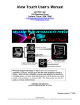
View Touch User’s Manual
KEYTEC, INC. 520 Shepherd Dr., Garland, Texas, USA 75042
http://www.magictouch.com/ViewTouch.html Email: [email protected]
Revised on May 10th, 2006
The following setup instructions are for installing View Touch 2.01F on Windows 2000 & XP, and View Touch 1.91 on Windows 98.
Note: Uninstall the previous version first (if any) by clicking on Start > Programs > View Touch > Uninstall.
1. Please read the instructions carefully.
Improper installation may cause permanent damages, which may not be covered by the warranty.
2. Check all the parts in the package against the following parts list.
One Digital Light Sensor (Part No. VT-DC1)
One Dual Level Laser Pen (Part No. VT-LP1)
One Tabletop Tripod (Part No. VT-TP1)
One Installation CD (VT-CD1)
One User’s Manual CD (Part No. VT-UM1)
Two AA Batteries
One Warranty Card
3. Minimum System Requirements:
PIII 850MHz CPU , 128MB RAM, CD ROM, 1 Mb Hard Drive Space, USB port, Windows 98/2000/XP.
4. Software Installation:
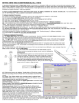
4.1. Insert the installation CD into your computer’s CD ROM. If you have downloaded View Touch 2.0 from our website, run setup.exe.
4.1.1. Click Install View Touch.
4.1.3. Installing driver, click Finish when it is done.
4.1.2. Click Yes or No depending on your preference. This option can be changed later.
4.1.4. Check I accept the agreement. Click Next.
If it is installed on Windows 98, you will first be prompted with “This will install Microsoft DirectX 8.1, do you want
to continue?” Click yes to this agreement window. After installation is completed, click ok to exit.
4.1.6. Click Finish.
4.1.5. Click Next.
4.1.7. Click EXIT.
4.1.8.
View Touch” and “View Touch Pen” icons are added on the desktop.
4.1.9. If you need to uninstall this installation, click start > programs > View Touch > uninstall.
4.2. Plug the digital light sensor into USB port.
4.2.1. For Windows 98 installation, Windows will update the driver information automatically. Continue to 5. Set Up and Calibration.
4.2.2. For Windows 2000 installation, you will be prompted for “Digital Signature Not Found”.
Click Yes. Continue to 5. Set Up and Calibration.
4.2.3. For Windows XP installation
Check Yes, this time only, then click Next.
4.2.4. Check Install the software automatically, and then click Next.
4.2.5. Click Continue Anyway.
4.2.6. Click Finish. Continue to 5. Set Up and Calibration.
5. Setup and Calibration:
5.1. The digital sensor can be mounted on any camera tripod (a tabletop tripod is included). You may also clip it to your notebook or mount it to the ceiling.
on tripod
on notebook
on ceiling
If you use the tabletop tripod provided, loosen the black knob and turn the mounting head side way so it is vertical to the tripod. Mount the digital light sensor onto it as shown above. The
distance required between the screen and sensor is approximately twice of the width of the screen. For example, if the width of the screen is 5 feet, then the sensor needs to be set at
about 10 feet away from the screen. The digital light sensor can be rotated horizontally to view left and right, and tilted vertically to view up and down, but the level needs to be adjusted
from the tripod after loosing the black knob.
5.2. For best result, the light sensor should be positioned as near as the center line of the screen. The View Touch can work effectively for most applications when the sensor is positioned
up to 15 degrees from the center lines, but there will be slightly uneven sensitivity due to the different distances between the sensor and the screen.
Center line from top view
Center line from side view
5.3. The laser pointer provided is designed with dual-level intensity. Different versions of laser pointer have been provided with View Touch. If your laser pointer has two buttons, then one
button is for switching on the low-intensity light (guiding light), and another button is for switching on the high-intensity light (activating light). If your laser pointer has only one button, press
it lightly half-way down to switch on the low-intensity light (guiding light), press it all the way down to switch on the high-intensity light (activating light).
5.4. Double click the View Touch icon
to open the setup screen.
Check proper selections to match your View Touch setup.
5.4.1. Display Type: If you use LCD, PDP, CRT type of display, use the laser pen to project a laser dot to the display to check if you can see a bright red dot on the
screen. If you cannot see a clear and bright red dot, then the View Touch sensor cannot see it either. View Touch should work on most PDP and CRT because they
have glass surface which reflects laser light. Some LCD’s also have a piece of protective glass in front, and those should be suitable for View Touch. Most projection
screens should be suitable for View Touch except for those have special treated anti-reflective surface that absorbs the laser light, so the sensor cannot detect it.
5.4.2. Sensor Orientation: Select how sensor is mounted. Ceiling mount may make sensor upside down.
5.4.3. Sensor Location: In most cases, sensor will be located in front of the screen. Only when rear projection is used, sensor could be located behind the screen.
5.4.4. Startup Automatically: When this option is enabled, View Touch will be automatically loaded with previous stored calibration data and ready to run.
5.4.5. Default button returns all the selections to default setting. Start button starts View Touch setup program. Exit button quits the setup.
5.5. After clicking the Start button, you should see the following screen. There is a picture-in-picture window in the center of the screen where shows whatever the sensors sees, but in a
pink-red color. Adjust the position (distance and angle) of the digital light sensor, until the entire displayed image is within the center of picture-in-picture window. Try to avoid bright spot
on the screen because the sensor might see it as a constant activation and can cause the mouse cursor stuck in that area. The bright spot is generally caused by strong light, such as
projector light or room lamps. Adjust the angle of projector or screen, or room lamps to avoid their lights from being reflected back to the sensor.
Try to maximize the viewed image within the window for best result. To make sure the entire image is viewed by the digital light sensor, it is recommended to use the laser pen to point at 4
extreme corners of the image and see if the bright spots can be seen within the picture-in-picture window, as shown in the following.
5.6. Click Calibration. The program will project a grid on the screen and takes a screen shot of that, then put it into the picture-in-picture window.
If you don’t see the complete pattern, either the digital light sensor cannot see the entire image or the lighting is too strong and “washes off” the image. Click Reset and do the necessary
adjustments, then click Calibration again. To do the calibration, use your mouse to place the cursor at the center of each cross point in the grid; then click the left mouse button to record
that calibration point. Start from the left-upper corner and follow the clockwise sequence as shown. IF YOU DO NOT FOLLOW THE CORRECT SEQUENCE, THE CALIBRATION WILL
BE INCORRECT.
After all 9 cross points have been clicked, you will be prompted to adjust the sensitivity bar and test the accuracy with laser pen, click ok to continue (see 5.9). If you think you did not click
each point accurately, then click Calibration to repeat the process. Note: After the calibration, the image in the window turns dark. If you need to adjust the digital light sensor position,
click Reset to brighten the image to pink-red color. Once the image turns into pink-red color, the laser pointer does not activate the mouse function.
If all the settings remain unchanged, the next time you start the View Touch, you may just click Load Calibration, and the last calibration data will be loaded.
5.7. After calibration, you will need to set the sensitivity level (at right side of the screen) for the laser pointer. The brighter the room, the higher the sensitivity needs to be set. However,
when the sensitivity is set too high, the performance may become unstable. In general, it is recommended to begin testing with sensitivity set at its middle point. The sensitivity bar can be
controlled by mouse and keyboard up/down arrow keys (useful for fine tuning). The laser pointer provided has dual level of intensity. The low-intensity level is used as a guiding light, thus
it should not activate the mouse cursor. Only the high-intensity level activates the mouse. Point the laser pointer to the screen and test both levels alternatively to set the correct sensitivity
level. Also check the accuracy of cursor position versus laser spot. If it is not accurate enough, redo the calibration.
5.8. Once the sensitivity bar is correctly set and the accuracy is satisfactory, the View Touch is ready for operation. There are three speed levels you can chose by clicking the top button
from Smooth (default) to Super Smooth to Fast. If your application typically uses point and click only, you can select Fast for faster response. If you want to perform more smooth drawing
or writing, then you should select Super Smooth mode. You may also consider adding a KEYTEC’S touch screen on your notebook or computer monitor for drawing/writing resolution
enhancement. After all the setting is completed, click Minimize to minimize the setup screen or click View Touch Pen if you want to launch the annotation program (see 6.2).
6. How to use View Touch
6.1. To accommodate double clicking with the View Touch, it is recommended to set the double click speed to slow in your mouse settings. You can also use folder option to set single click
to open icon to eliminate the need of performing a double click. Press low-intensity switch to turn on the guiding light. Aim the target with guiding light, then press high-intensity switch to
activate the mouse movement and click. For dragging, hold down the switch and move the laser pointer. You may practice from a short distance first, and then gradually increase the
distance from the screen. For rear projection user, you may point the laser directly onto the screen. If the surface of the screen tends to adsorb or diffuse the laser light, using a red LED
may solve the problem, but you need to point the LED directly onto the screen.
After a little practice, you will learn to use the View Touch like a wireless remote mouse control.
6.2. The annotation program, View Touch Pen, is designed as a presentation tool. Double click the View Touch Pen icon to open it. Click on the mouse button,
and it extends to show 6 more buttons. The two Arrow Buttons are designed for use with MS Power Point slide shows to navigate forward and back through the
slides. The Swap Mouse button is used to change from performing a left mouse click to a right-mouse click. Click the X to close the program.
Click on the Pen button, it extends into more functional buttons for annotation purpose. There are 4 Colors to choose from. You can use it to draw, mark and
write on the screen. Click on the Save button to save the entire screen as a snap shot in BMP or JPG format. Other buttons perform the Undo, Redo and
Delete functions. Please note when in the pen mode, the mouse click function is disabled. Click the Arrow button at the bottom to return to mouse control
functions.
The View Touch can be used in conjunction with other useful utility software such as on-screen keyboard and hand writing recognition programs. It can also be
used concurrently with KEYTEC’S Magic Touch screens for writing/drawing enhancement. (more information available at www.magictouch.com)
7. Troubleshooting
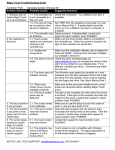
7.1. Error message when opening View Touch: No video capture device was detected on your system.
* Check and make sure the digital light sensor is connected to your computer’s USB port.
* If you plug in the digital sensor to a USB port which is not the device originally installed to, you must go through the steps listed in 4.2 to enable the sensor on
this new port.
* If your View Touch is already running, do not double click the icon on desktop to reopen it. Use the mouse right click to maximize the View Touch icon at the
bottom of the task bar.
* If you use a USB extension cable, make sure it is specified for the length that you extend it to. It is recommended to use “active” USB extension cable.
7.2. Cannot get viewed image into picture-in-picture window:
* No matter how you adjust the sensor’s distance and angle, you just cannot get the viewed image into the window. There are a few models of notebook
computer have presented this kind of problem when both notebook’s LCD and projection screen have image displayed. Turn off the image on notebook.
* If you use a USB extension cable, make sure it is specified for the length that you extend it to. It is recommended to use “active” USB extension cable.
7.3. Not accurate after calibration:
* No matter how carefully you have calibrated, the mouse cursor is far away from the laser light. There are a few models of notebook computer have presented this kind of
problem when both notebook’s LCD and projection screen have image displayed. Turn off the image on notebook.
7.4. Can not see the complete calibration grid:
* If part of the grid is missing, you may need to adjust the digital light sensor angle or increase the distance between digital light sensor and the screen in order to view the
entire screen.
* If part of the grid is obscured by a white color splotch and cannot be seen; it is likely caused by the View Touch being under lighting that is too strong. Try to dim the lights
and reset.
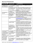
7.5. The cursor is stuck to the edge of the screen:
* Check if there is any reflective material (such as metal frame) or some lights (such as the indicator LED). Cover them if any.
7.6. The cursor is stuck in the middle of the screen:
* Check if there is a bright spot caused by the projector. Adjust the angle or change the fabric of the screen to avoid this kind of problem.
7.7. Can not see the guiding light:
* The guiding light is weak. It takes a little while for your eyes to get used to it. It is more visible in dimly lit rooms and on screen colors that provide good contrast to the red color of the
laser. If the laser pen has been used for some time, you may need to change the batteries.
7.8. The mouse control function is not sensitive enough:
* Check if the ambient lighting condition is changed since last adjusting the sensitivity.
* Check if the batteries need to be replaced.
* Adjust the sensitivity bar to optimize the performance.
7.9. The View Touch is not sensitive on part of the screen:
* Check if the digital light sensor has been set up at an angle greater than 15 degrees from the center point of the screen.
7.10. The View Touch stop responding after I change the display resolution, or the display resolution is changed by certain program:
* Maximize the View Touch from the bottom task bar, and test it with laser pointer. If mouse follows, minimize the View Touch. If mouse does not follow, exit the View Touch. Unplug the
USB cable and plug it back in. Start the View Touch and click Load Calibration.
For assistance, please contact KEYTEC: Email: [email protected] Tel: 800-MAGIC-89 (9AM to 5PM CST Monday to Friday).
8. Warranty: LIMITED ONE-YEAR PART AND LABOR WARRANTY:
KEYTEC will supply, at no charge, new or a rebuilt part in exchange of the defective one for a period of one year from the date of purchase.
You must first notify KEYTEC'S technical support dept. by sending e-mail to [email protected] or calling 800-MAGIC-89 (9AM-5PM, CST, Monday to Friday) to report the problem. If
the technical support personnel have determined that your Magic Touch product needs to be serviced, you will be given a RMA# (Return Merchandise Authorization Number) for sending
your product in for service. You must deliver the product freight prepaid in the original package or package with equal degree of protection to the authorized service station as instructed by
technical support department. The RMA# must be clearly marked outside of the package. Your return address must be included. If the product is out of the warranty, you will be quoted
for the replacement or repair cost. No work will be performed until your approval on all the charges is confirmed.
WHAT'S NOT COVERED?
Products that have been previously altered, repaired or serviced by unauthorized personnel, or serial number on the products has been altered or removed, or cosmetic damages and
physical damages, or damages due to improper installation, operation or connection to improper voltage supply, or any damages due to misuses, abuses, negligence, unauthorized
modifications, accidents and acts of God, or those products which were sold AS IS or WITH ALL FAULTS.
9. Please send your comments, compliments or complaints to [email protected].
FCC COMPLIANCE
This equipment has been listed and found to comply with the limits for a Class B digital device, pursuant to Part 15, Subpart B of FCC Rules. This equipment generates, uses, and can
radiate radio frequency energy. If not installed and used in accordance with the instructions, it may cause interference to radio communications. The limits are designed to provide
reasonable protection against such interference in a residential situation. There is no guarantee that interference will not occur in a particular installation.
DISCLAIMER
The material in this document is for an informational purpose and is subject to change without notice. The manufacturer assumes no responsibility for errors or omissions in this document.
Nor are any liability assumed for any damages from the use of this product and the information contained in this document. All mentioned product names herein are registered trademarks
of the respective companies.
REGISTERED TRADEMARKS
KEYTEC, VIEW TOUCH and MAGIC TOUCH are registered trademarks of KEYTEC, INC.
All rights reserved. No part of this document and the software provided with the product may be reproduced or modified without permission of the
manufacturer.
KEYTEC, INC. 520 Shepherd Dr., Garland, Texas, USA 75042
http://www.magictouch.com/ViewTouch.html Email: [email protected]