1
RFID System
V600 Series
User's Manual
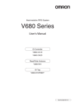
Hand-held Reader Writer
V600-CHUD
Data Carriers
V600 Series
Cat. No. Z219-E1-01
Application Considerations (Read and understand this information first.)
Section 2 Communications Preparations
Section 3 Commands
Section 4 Functions
Section 5 Troubleshooting
Section 6 Appendices
RFID System
V600-CHUD
Hand-held Reader Writer
User’s Manual
Section
ëÊ 1 èÕ1 Section
ëÊ 2 èÕ2 Section
ëÊ 3 èÕ3 Section
ëÊ 4 èÕ4 Section 5 Section 6
Section 1 Product Overview
Introduction
ÇÕǹÇ?Ç
Introduction
Introduction
Introduction
READ AND UNDERSTAND THIS DOCUMENT
Please read and understand this document before using the products. Please consult your OMRON representative if you have any questions or comments.
WARRANTY
OMRON’s exclusive warranty is that the products are free from defects in materials and workmanship for a period of one year (or other period if specified)
from date of sale by OMRON.
OMRON MAKES NO WARRANTY OR REPRESENTATION, EXPRESS OR IMPLIED, REGARDING NON-INFRINGEMENT, MERCHANTABILITY, OR
FITNESS FOR PARTICULAR PURPOSE OF THE PRODUCTS. ANY BUYER OR USER ACKNOWLEDGES THAT THE BUYER OR USER ALONE HAS
DETERMINED THAT THE PRODUCTS WILL SUITABLY MEET THE REQUIREMENTS OF THEIR INTENDED USE. OMRON DISCLAIMS ALL OTHER
WARRANTIES, EXPRESS OR IMPLIED.
LIMITATIONS OF LIABILITY
OMRON SHALL NOT BE RESPONSIBLE FOR SPECIAL, INDIRECT, OR CONSEQUENTIAL DAMAGES, LOSS OF PROFITS OR COMMERCIAL LOSS IN
ANY WAY CONNECTED WITH THE PRODUCTS, WHETHER SUCH CLAIM IS BASED ON CONTRACT, WARRANTY, NEGLIGENCE, OR STRICT
LIABILITY.
In no event shall responsibility of OMRON for any act exceed the individual price of the product on which liability is asserted.
IN NO EVENT SHALL OMRON BE RESPONSIBLE FOR WARRANTY, REPAIR, OR OTHER CLAIMS REGARDING THE PRODUCTS UNLESS OMRON’S
ANALYSIS CONFIRMS THAT THE PRODUCTS WERE PROPERLY HANDLED, STORED, INSTALLED, AND MAINTAINED AND NOT SUBJECT TO
CONTAMINATION, ABUSE, MISUSE, OR INAPPROPRIATE MODIFICATION OR REPAIR.
SUITABILITY FOR USE
THE PRODUCTS CONTAINED IN THIS DOCUMENT ARE NOT SAFETY RATED. THEY ARE NOT DESIGNED OR RATED FOR ENSURING SAFETY OF
PERSONS, AND SHOULD NOT BE RELIED UPON AS A SAFETY COMPONENT OR PROTECTIVE DEVICE FOR SUCH PURPOSES. Please refer to
separate catalogs for OMRON's safety rated products.
OMRON shall not be responsible for conformity with any standards, codes, or regulations that apply to the combination of products in the customer’s
application or use of the product.
At the customer’s request, OMRON will provide applicable third party certification documents identifying ratings and limitations of use that apply to the
products. This information by itself is not sufficient for a complete determination of the suitability of the products in combination with the end product,
machine, system, or other application or use.
The following are some examples of applications for which particular attention must be given. This is not intended to be an exhaustive list of all possible uses
of the products, nor is it intended to imply that the uses listed may be suitable for the products:
• Outdoor use, uses involving potential chemical contamination or electrical interference, or conditions or uses not described in this document.
• Nuclear energy control systems, combustion systems, railroad systems, aviation systems, medical equipment, amusement machines, vehicles, safety
equipment, and installations subject to separate industry or government regulations.
• Systems, machines, and equipment that could present a risk to life or property.
Please know and observe all prohibitions of use applicable to the products.
NEVER USE THE PRODUCTS FOR AN APPLICATION INVOLVING SERIOUS RISK TO LIFE OR PROPERTY WITHOUT ENSURING THAT THE SYSTEM
AS A WHOLE HAS BEEN DESIGNED TO ADDRESS THE RISKS, AND THAT THE OMRON PRODUCT IS PROPERLY RATED AND INSTALLED FOR THE
INTENDED USE WITHIN THE OVERALL EQUIPMENT OR SYSTEM.
PERFORMANCE DATA
Performance data given in this document is provided as a guide for the user in determining suitability and does not constitute a warranty. It may represent the
result of OMRON’s test conditions, and the users must correlate it to actual application requirements. Actual performance is subject to the OMRON Warranty
and Limitations of Liability.
CHANGE IN SPECIFICATIONS
Product specifications and accessories may be changed at any time based on improvements and other reasons.
It is our practice to change model numbers when published ratings or features are changed, or when significant construction changes are made. However,
some specifications of the product may be changed without any notice. When in doubt, special model numbers may be assigned to fix or establish key
specifications for your application on your request. Please consult with your OMRON representative at any time to confirm actual specifications of purchased
products.
DIMENSIONS AND WEIGHTS
Dimensions and weights are nominal and are not to be used for manufacturing purposes, even when tolerances are shown.
ERRORS AND OMISSIONS
The information in this document has been carefully checked and is believed to be accurate; however, no responsibility is assumed for clerical, typographical,
or proofreading errors, or omissions.
PROGRAMMABLE PRODUCTS
OMRON shall not be responsible for the user’s programming of a programmable product, or any consequence thereof.
COPYRIGHT AND COPY PERMISSION
This document shall not be copied for sales or promotions without permission. This document is protected by copyright and is intended solely for use in
conjunction with the product. Please notify us before copying or reproducing this document in any manner, for any other purpose. If copying or transmitting
this document to another, please copy or transmit it in its entirety.
2
RFID System
User's Manual
Introduction
Introduction
Meanings of Signal Words
WARNING
Indicates a potentially hazardous situation which, if not avoided, will result in minor or moderate
injury, or may result in serious injury or death. Additionally, there may be significant property
damage.
CAUTION
Indicates a potentially hazardous situation which, if not avoided, may result in minor or moderate
injury or in property damage.
Meanings of Signal Words
The following signal words are used in this manual.
Meanings of Alert Symbols
The following alert symbols are used in this manual.
Indicates the possibility of explosion under specific conditions.
Indicates general prohibitions for which there is no spacific symbol.
Alert statements in this Manual
The following alert statements apply to the products in this manual. Each alert statement also appears at the locations
needed in this manual to attract your attention.
WARNING
This product is not designed to be used either directly or indirectly in applications that detect
human presence for the purpose of maintaining safety. Do not use this product as a sensing device
for protecting human lives.
A lithium battery is built into SRAM Data Carriers and may occasionally combust, explode, or burn
if not treated properly. Dispose of SRAM Data Carriers as industrial waste and never disassemble,
apply pressure that would deform, heat to higher than 100°C, or incinerate SRAM Data Carriers.
RFID System
User's Manual
3
Introduction
Introduction
Regulations and Standards
Regulations and Standards
The V600-CHUD series complies with the following standards.
1. FCC (USA Federal Communications Commission)
FCC Part 15 Subpart C
FCC ID:E4E6CYCIDV6000203
2. Europe Radio and EMC Standards
The requirements of the EC/R&TTE Directive (Radio and Telecommunications Terminal Equipment Directive 1999/5/EC)
have been met.
Radio: EN300330-2 V1.1.1(06-2001) EN300300-1 V1.3.1(06-2001)
EMC: EN301489-3 V1.4.1(08-2002) EN301489-1 V1.4.1(08-2002)
Safety: EN61010-1:2001(2ND Edition)
Countries of intended use:
Finland, Germany, Iceland, Sweden
4
English
Hereby, Omron, declares that this V600-CHUD(-X) is in compliance with the essential
requirements and other relevant provisions of Directive 1999/5/EC.
Finnish
Omron vakuuttaa täten että V600-CHUD(-X) tyyppinen laite on direktiivin 1999/5/EY
oleellisten vaatimusten ja sitä koskevien direktiivin muiden ehtojen mukainen.
Swedish
Härmed intygar Omron att denna V600-CHUD(-X) stär l överensstämmelse med de
väsentliga egenskapskrav och övriga relevanta bestämmelser som framgår av direktiv
1999/5/EG.
German
Hiermit erklärt Omron, dass sich dieser/diese/dieses V600-CHUD(-X) in Übereinstimmung
mit den grundlegenden Anforderungen und den anderen relevanten Vorschriften der
Richtlinie 1999/5/EG befindet. (BMWi)
RFID System
User's Manual
Introduction
Introduction
Precautions for Safe Use
Regulations and Standards
Observe the following precautions to ensure safe use of the product.
1. Do not use the product in environments with flammable, explosive, or corrosive gasses.
2. Do not attempt to disassemble, repair, or modify the product.
3. The USB driver must be installed in the personal computer before connecting the V600-CHUD to a
personal computer.
4. Do not subject cables to excessive loads.
5. Observe all warnings and precautions given in the body of this manual.
6. Discontinue usage and turn OFF the power supply immediately if you notice any unusual odors, if the
product is abnormally hot, or if the product starts smoking.
7. When disposing of the product, treat it as industrial waste.
Precautions for Correct Use
Always observe the following precautions to prevent operation failures, malfunctions, and adverse effects on
performance and equipment.
1. Installation Environment
Install the product in the following locations:
• Locations not subject to corrosive gas, dust, metallic powder, or salt.
• Locations within the specified operating temperature range.
• Locations not subject to rapid changes in temperature (with no condensation).
• Locations within the specified humidity range.
• Locations not subject to direct vibration or shock outside the specified ranges.
• Locations not subject to water, oil, or chemicals.
2. Installation
• The product communicates with Data Carriers using the 530-kHz frequency band. Some motors,
inverters, switching power supplies, and other devices generate noise that can affect communications with the Data Carriers. If such devices are located near the Data Carriers, communications
with the Data Carriers may be adversely affected or the Data Carriers may be destroyed. Whenever
using the product near devices of this nature, always test operation in advance to confirm if the system will be affected.
• Observe the following precautions to minimize the effects of normal noise.
(1) Ground all metal objects in the vicinity to 100 Ω or less.
(2) Do not use the system near high-voltage or high-current lines.
• Connectors are not waterproof. Do not use the product where mists are present.
• Do not use chemicals that would affect the materials used in the product.
• Always be sure the USB connector is properly inserted when using the USB port.
3. Cleaning
• Do not clean the product with thinners, benzene, or other organic solvents. These will dissolve the
resin parts and coating on the case.
RFID System
User's Manual
5
Introduction
Introduction
How to Read this Manual
How to Read this Manual
Meanings of Symbols
Indicates particularly important points related to a function, including precautions and application advice.
Indicates page numbers containing relevant information.
Indicates reference to helpful information and explanations for difficult terminology.
6
RFID System
User's Manual
Introduction
Introduction
Table of Contents
Meanings of Signal Words
3
Meanings of Alert Symbols
3
Alert statements in this Manual
3
Precautions for Safe Use
5
Precautions for Correct Use
5
How to Read this Manual
6
Table of Contents
7
Section 1 Product Overview
9
Features
10
Names and Functions of Components
11
System Configuration
12
Operation Flowchart
13
Section 2 Communications Preparations
15
Connections
16
Installing the USB Driver
17
Communications Test
26
Section 3 Commands
29
Communications with the Data Carrier
30
Command and Response Format
34
Communications Commands
38
Communications Subcommands
77
Host Commands
78
Evaluation Commands
79
Other Commands
81
End code List
82
RFID System
User’s Manual
7
Introduction
Introduction
Section 4 Functions
Hand-held Reader Writer Functions
84
Data Carrier
85
Section 5 Troubleshooting
95
Error Tables
96
Troubleshooting Flowchart
97
Section 6 Appendices
8
83
99
Specifications and Dimensions
100
Data Carrier Memory Map
106
Data Carrier Memory Capacity and Data Type (V600 Series)
107
List of ASCII Characters
108
Degree of Protection
109
Revision History
111
RFID System
User’s Manual
Section 1
Section 1
Product Overview
10
Names and Functions of Components
11
System Configuration
12
Operation Flowchart
13
RFID System
User’s Manual
Product Overview
Features
9
Section 1
Product Overview
Features
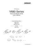
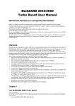
The V600-CHUD Hand-held Reader Writer incorporates a V600-series Antenna and Controller into a compact
Section 1 Features
device conforming to USB 1.1. Data can be read from or written to the Data Carrier simply by approaching or
touching the Data Carrier with the Hand-held Reader Writer.
Personal computer
Hand-held Reader Writer
Data Carriers
10
RFID System
User’s Manual
Section 1
Product Overview
Names and Functions of Components
V600-CHUD
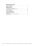
Section 1 Names and Functions of Components
Antenna
•Operation Indicator (LED)
Display
Operation indicator (LED)
Meaning
A command has been received from the host device.
Communications with the Data Carrier have completed normally.
Activate switch
Lit green
The execution result of the noise detection command (NS) is "A" (low
noise).
The result of the error noise detection command (EN) is "0" (normal).
When the power is turned ON, after initialization of the Hand-held
Reader Writer is completed
Communications with the Data Carrier are in progress.
Flashing green
A communications error with the Data Carrier has occurred.
A CPU error has occurred.
Lit red
A Data Carrier non-existent error has occurred.
A communications error with the host device has occurred.
Flashing red
The execution result of the noise detection command (NS) is "B" (high
noise).
The result of the error noise detection command (EN) is "1" (error).
Interface connector
After the operation indicator is lit or flashing for a certain time, it will turn OFF.
•Activate Switch
When button commands (button commands, button auto commands) are
used and the activate switch is pressed, communications with the Data
Carrier will commence. (For details on button commands, refer to Section
3 Commands.)
•Interface Connector
This is a USB interface with an A-series plug based on USB 1.1.
•Antenna
To communicate with the Data Carrier, move the antenna head closer to
it.
RFID System
User’s Manual
11
Section 1
Product Overview
System Configuration
V600-CHUD
Section 1 System Configuration
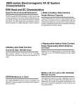
The V600-CHUD Hand-held Reader Writer can communicate with host devices that have a USB interface
such as personal computers.
Host Devices
Personal computer
Handheld Reader Writer
Data Carriers
The V600-CHUD Hand-held Reader Writer can be used with any Data Carrier in the V600 Series.
For details on Hand-held Reader Writer and Data Carrier models, refer to Section 6 Appendices.
p.100, p.107
12
RFID System
User’s Manual
Section 1
Product Overview
Section 1 Operation Flowchart
Preparation
Operation Flowchart
Connect the V600-CHUD to the host device.
When connecting for the first time, the USB driver must be installed.
p.16 p.17
Perform the communications test between the host device and
Hand-held Reader Writer.
Test
p.27
Perform the communications test between the Data Carrier
and Hand-held Reader Writer.
p.27
Check the ambient environment.
Transmission
p.100
Operate the system using real commands.
p.29
RFID System
User’s Manual
13
Section 1
Product Overview
MEMO
Section 1 Operation Flowchart
14
RFID System
User’s Manual
Section 2
Communications Preparations
Section 2
16
Installing the USB Driver
17
Communications Test
26
RFID System
User's Manual
Communications Preparations
Connections
15
Section 2
Communications Preparations
Connections
Connecting the Cable
Section 2 Connections
1. Connect the cable connector to the USB connector on the host
device, making sure that the connector is oriented correctly
and not inserted at an angle.
Removing the Cable
1. Remove the cable.
Close the software application at the host device and then pull out the connector in a straight line.
If the connector is removed while the software is running at the host
device, operation may stop due to a software malfunction error.
16
RFID System
User's Manual
Section 2
Communications Preparations
Installing the USB Driver
When connecting the Hand-held Reader Writer to the host device for the first time, the USB driver must be
installed at the host device.
Install the USB Driver in the Personal Computer
Section 2 Installing the USB Driver
The V600-CHUD supports Windows 2000 and Windows XP operating systems. Install the driver in the
host device follwoing the procedure correspondign to the OS being used.
Operation on other OS is not supported.
• Windows 2000
1. Turn ON the power to the personal computer and start Windows 2000.
2. Connect the Hand-held Reader Writer to the personal computer.
For details on connection methods, refer to Connections.
p.16
The following window will be displayed when the Hand-held Reader Writer is connected.
3. When the following window is displayed, click the Next Button.
RFID System
User's Manual
17
Section 2
Communications Preparations
4. Select Search for a suitable driver for my device (recommended) and then click the Next Button.
Section 2 Installing the USB Driver
5. Select Specify a location and then click the Next Button.
6. Click the Browse Button, and select the folder in which the downloaded file RFID-Win2kcom.inf is
saved.
18
RFID System
User's Manual
Section 2
Communications Preparations
7. Click the Next Button.
Section 2 Installing the USB Driver
The following window will be displayed when software installation is completed.
8. Click the Finish Buttton.
RFID System
User's Manual
19
Section 2
Communications Preparations
Checking Installation
Check that the driver is correctly installed.
1. Connect the Hand-held Reader Writer to the personal computer.
Section 2 Installing the USB Driver
20
2. On the Start Menu, select Settings - Control Panel - System.
3. Select the Device Manager Button on the Hardware Tab Page.
RFID System
User's Manual
Section 2
Communications Preparations
4. Select Ports (COM & LPT), and check that OMRON RFID USB COM is displayed.
The driver is correctly installed if this port is displayed.
Section 2 Installing the USB Driver
Communications with the Hand-held Reader Writer can be performed with the port number displayed in parentheses after
OMRON RFID USB COM.
RFID System
User's Manual
21
Section 2
Communications Preparations
• WindowsXP (SP1)
1. Turn ON the power to the personal computer and start Windows XP.
Section 2 Installing the USB Driver
2. Connect the Hand-held Reader Writer to the personal computer.
For details on connection methods, refer to Connections.
p.16
Wait for the following window to be displayed.
3. When the following window is displayed, select Install from a list or specific location (Advanced)
and click the Next Button.
22
RFID System
User's Manual
Section 2
Communications Preparations
4. Click the Browse Button, and select the folder in which the downloaded file RFID-Win2kcom.inf is
saved. Then click the Next Button.
Section 2 Installing the USB Driver
5. Click the Continue Anyway Button.
When the following window is displayed, installation is completed.
6. Click the Finish Button.
RFID System
User's Manual
23
Section 2
Communications Preparations
Checking Installation
Check that the driver is correctly installed.
1. Connect the Hand-held Reader Writer to the personal computer.
Section 2 Installing the USB Driver
24
2. On the Start Menu, select Control Panel - Performance and Maintenance.
3. Click the System Icon.
4. Click the Device Manager Button in the Hardware Tab Page.
RFID System
User's Manual
Section 2
Communications Preparations
5. Select Ports (COM & LPT), and check that OMRON RFID USB COM is displayed.
The driver is correctly installed if this port is displayed.
Section 2 Installing the USB Driver
Communications with the Hand-held Reader Writer can be performed with the port number displayed in parentheses after
OMRON RFID USB COM.
RFID System
User's Manual
25
Section 2
Communications Preparations
Communications Test
Test Run Procedure
Section 2 Communications Test
Connect the Hand-held Reader Writer
to the host device.
Visually check the indicator display.
Execute the online test from the host
Check communications between the host device and Hand-held Reader
device.
Writer using the test command.
Test run the system.
Finish
26
RFID System
User's Manual
Check operation using real commands.
Section 2
Communications Preparations
Communications Test Between Host Device and Hand-held
Reader Writer
Use the test command to test communications between the Hand-held Reader Writer and host device.
Before performing communications with the Data Carrier, check the Hand-held Reader Writer connections and communications.
Section 2 Communications Test
1. Send the test command from the host device.
For detail on the test command, refer to TEST (TS).
p.78
2. If communications is normal, the Hand-held Reader Writer will return the received data.
If a response is not returned, refer to Troubleshooting.
p.95
Communications Test Between the Data Carrier and Hand-held
Reader Writer
Use a real command to test communications between the Data Carrier and the Hand-held Reader
Writer.
1. Send the auto read command (AR) from the host device.
For details on the auto read command, refer to AUTO READ (AR).
p.42
The Hand-held Reader Writer will communicate with the Data Carrier and the operation indicator will flash green.
2. Move the antenna section of the Hand-held Reader Writer close to the Data Carrier.
The Hand-held Reader Writer will read the data in the Data Carrier when the Hand-held Reader Writer moves within the communications range. As a result, the operation indicator will be light green and then turn OFF.
RFID System
User's Manual
27
Section 2
Communications Preparations
MEMO
Section 2 Communications Test
28
RFID System
User's Manual
Section 3
Commands
Command and Response Format
34
Communications Commands
38
Communications Subcommands
77
Host Commands
78
Evaluation Commands
79
Other Commands
81
End code List
82
RFID System
User’s Manual
Commands
30
Section 3
Communications with the Data Carrier
29
Section 3
Commands
Communications with the Data Carrier
There are 4 types of commands for communicating with the Data Carrier using the Hand-held Reader Writer.
•Normal commands
•Button commands
•Auto commands
•Button auto commands
Normal Commands
Section 3 Communications with the Data Carrier
Normal commands are sent from the host device for communications with the Data Carrier, after the
antenna end of the Hand-held Reader Writer has been moved close to the Data Carrier.
1. Move the antenna end of the Hand-held Reader Writer close to the Data Carrier.
1
Host device
Data Carrier
Hand-held Reader Writer
3
2
Command
Communications
with Data Carrier
4
Response
2. Commands are sent from the host device to the Hand-held Reader Writer.
3. The Hand-held Reader Writer communicates with the Data Carrier.
4. A response is returned from the Hand-held Reader Writer to the host device.
If communications are normal, the operation indicator (LED) lights green and then turns OFF.
If the Data Carrier is not detected within the Hand-held Reader Writer's communication area when the
command is sent from the host device, a Data Carrier Non-existent Error will occur.
At this time, the operation indicator will flash red.
30
RFID System
User's Manual
Section 3
Commands
Button Commands
Button commands used to perform communications with the Data Carrier are activated when the activate switch is pressed after commands are sent from the host device, and the antenna end of the
Hand-held Reader Writer has been moved close to the Data Carrier.
Host device
Data Carrier
Hand-held Reader Writer
Press
Section 3l Communications with the Data Carrier
Communications
with Data Carrier
Command
Response
1. A command is sent from the host device to the Hand-held Reader Writer. As a result, the operation
indicator will light green.
2. Move the antenna end of the Hand-held Reader Writer close to the Data Carrier.
2
3. Press the Hand-held Reader Writer activate switch.
4. The Hand-held Reader Writer communicates with the Data Carrier.
5. A response is returned to the host device from the Hand-held Reader Writer.
If communications are normal, the operation indicator (LED) lights green and then turns OFF.
If the Data Carrier is not detected within the Hand-held Reader Writer's communication area when the
activate switch is pressed, a Data Carrier Non-existent Error will occur.
At this time, the operation indicator will flash red.
RFID System
User's Manual
31
Section 3
Commands
Auto Commands
Auto commands can execute communications with the Data Carrier when the antenna is moved near
the front of the Data Carrier after a command is sent from the host device.
Host device
Data Carrier
Hand-held Reader Writer
3
Section 3 Communications with the Data Carrier
Communications
with Data Carrier
1
Command
4
Response
1. A command is sent from the host device to the Hand-held Reader Writer.
2. The Hand-held Reader Writer enters the communication stand-by state with the Data Carrier, and the
operation indicator (LED) flashes green.
If the Data Carrier is not detected within one minute of sending the command, a timeout will occur and a Data Carrier
Non-existent Error will occur. As a result, the operation indicator will flash red.
3. Communications with the Data Carrier are performed when the antenna end of the Hand-held Reader
Writer is moved near the Data Carrier.
3
4. A response is returned from the Hand-held Reader Writer to the host device.
If communications end normally, the operation indicator (LED) lights green and then turns OFF.
32
RFID System
User's Manual
Section 3
Commands
Button Auto Commands
Button auto commands execute auto commands after a command is sent from the host device and the activate
switch of the Hand-held Reader Writer is pressed.
Host device
Data Carrier
Hand-held Reader Writer
2 Press
4
Section 3l Communications with the Data Carrier
Communications
with Data Carrier
1
Command
5
Response
1. A command is sent from the host device to the Hand-held Reader Writer.
2. Press the Hand-held Reader Writer activate switch.
3. The Hand-held Reader Writer enters the communication stand-by state with the Data Carrier, and the
operation indicator (LED) flashes green.
If the Data Carrier is not detected within one minute of sending the command, a timeout will occur and a Data Carrier
Non-existent Error will occur. As a result, the operation indicator will flash red.
4. Communications with the Data Carrier are performed when the antenna end of the Hand-held Reader
Writer is moved near the Data Carrier.
4
5. A response is returned from the Hand-held Reader Writer to the host device.
If communications end normally, the operation indicator (LED) lights green and then turns OFF.
RFID System
User's Manual
33
Section 3
Commands
Command and Response Format
The format of commands sent between the host computer and the Hand-held Reader Writer and responses
returned from the Hand-held Reader Writer to the host computer is shown below. The command and
response both consist of a single frame. The frame (including the terminator) consists of up to 4,106
characters for commands and 4,102 characters for responses.
1 frame
Command code
Section 3 Command and Response Format
×
Data
×
×
Terminator
×
2
×
CR
n
2
Name
Description
Command code
Command: Contains the two-character code (see page p.36).
Response: Contains the same code that was sent with the command.
Data
Contains the details of the command and response, as follows:
•ASCII/hexadecimal code specification, processing specification, mode specification
•Processing area number specification
•Processing start address
•Number of bytes to be read, write data
Terminator
Indicates end of command/response.
Specifying Data Code
Whether the read or write data is treated as an ASCII (or JIS 8) code or hexadecimal code is specified
in a command.
•ASCII (JIS 8 Code)
•One character of ASCII or JIS 8 code data occupies 1 byte (1 address) of the Data Carrier memory.
•Example of Specifying ASCII Code
W
T
A
1
Command code ASCII Processing
setting area number
setting
34
RFID System
User's Manual
0
0
1
Start address
0
•Data Carrier
O
M
R
Write data
O
N
CR
Terminator
Address
0010
4
F
"O"
0011
4
D
"M"
0012
5
2
"R"
0013
4
F
"O"
0014
4
E
"N"
Section 3
Commands
•Hexadecimal Code
•One character is treated as a hexadecimal number. Therefore, only numerals 0 through 9 and A to F
can be accepted.
•Two characters of data occupy 1 byte (1 address) of the Data Carrier memory. Therefore, specify data
in 2-character units (in even numbers) when using a WRITE command. If an odd number of characters is specified by mistake, an error will occur.
•Example of Specifying Hexadecimal Code
W
T
Command
code
H
1
Hexa- Processdecimal ing area
code
number
setting
setting
0
0
1
Start address
0
1
9
9
Write data
6
CR
Terminator
•Data Carrier
Address
1
9
0011
9
6
Section 3l Command and Response Format
0010
1 byte
RFID System
User's Manual
35
Section 3
Commands
Command List
Commands can be classified into four major types.
•Communications Commands
The following commands are used for communications with the Data Carrier.
Command code
Page
Section 3 Command and Response Format
READ
Reads memory data from the Data Carrier.
p.38
WT
WRITE
Writes data to the memory of the Data Carrier.
p.40
AR
AUTO READ
Reads data from the Data Carrier when the Data Carrier is within the
communications area.
p.42
AW
AUTO WRITE
Writes data to the memory of the Data Carrier when the Data Carrier is
within the communications area.
p.44
BR
BUTTON READ
Reads data from the memory of the Data Carrier when the activate
switch is pressed.
p.46
BW
BUTTON WRITE
Writes data to the memory of the Data Carrier when the activate switch
is pressed.
p.48
UR
BUTTON AUTO
READ
Reads data from the Data Carrier when the Data Carrier enters the
communications area after the activate switch is pressed.
p.50
UW
BUTTON AUTO
WRITE
Writes data to the memory of the Data Carrier when the Data Carrier
enters the communications area after the activate switch is pressed.
p.52
RC
COPY READ
Reads data to be copied using the COPY WRITE command from the
Data Carrier.
p.54
WC
COPY WRITE
Writes the data read using the COPY READ command to the Data
Carrier.
p.55
XR
EXPANSION
DIVIDED READ
Divides and reads up to 2 Kbytes of data from the Data Carrier.
XW
EXPANSION
DIVIDED WRITE
Divides and writes up to 2 Kbytes of data to the Data Carrier.
NR
EXPANSION
DIVIDED
AUTO READ
Divides and reads up to 2 Kbytes of data from the Data Carrier when
the Data Carrier enters the communications area.
p.60
EXPANSION
DIVIDED
AUTO WRITE
Divides and writes up to 2 Kbytes of data to the Data Carrier when the
Data Carrier enters the communications area.
p.62
rd
EXPANSION
BATCH READ
Reads up to 2 Kbytes of data from the Data Carrier in a batch.
wt
EXPANSION
BATCH WRITE
Writes up to 2 Kbytes of data to the Data Carrier in a batch.
ar
EXPANSION
BATCH
AUTO READ
Reads up to 2 Kbytes of data from the Data Carrier in a batch when the
Data Carrier enters the communications area.
p.66
EXPANSION
BATCH
AUTO WRITE
Writes up to 2 Kbytes of data to the Data Carrier in a batch when the
Data Carrier enters the communications area.
p.67
EXPANSION
BATCH
BUTTON READ
Reads up to 2 Kbytes of data from the Data Carrier in a batch after the
activate switch is pressed.
p.68
EXPANSION
BATCH
BUTTON WRITE
Writes up to 2 Kbytes of data to the Data Carrier in a batch after the
activate switch is pressed.
p.69
EXPANSION
BATCH BUTTON
AUTO READ
Reads up to 2 Kbytes of data from the Data Carrier in a batch when the
Data Carrier enters the communications area after the activate switch
is pressed.
aw
br
bw
ur
RFID System
User's Manual
Function
RD
NW
36
Command name
p.56
p.58
p.64
p.65
p.70
Section 3
Commands
Command code
Function
Page
EXPANSION
BATCH BUTTON
AUTO WRITE
Writes up to 2 Kbytes of data to the Data Carrier in a batch when the
Data Carrier enters the communications area after the activate switch
is pressed.
p.71
CW
CALCULATION
WRITE
Writes the calculation results for the memory data to the Data Carrier.
FL
FILL
Writes data for the specified number of write bytes beginning from the
write start address specified in the command.
p.73
EXPANSION
BATCH
FILL
Writes data for the specified number of write bytes beginning from the
write start address specified in the command. Up to 2 Kbytes of data
can be written in a batch.
p.74
DATA CHECK
Calculates or compares memory check codes in the Data Carrier.
p.75
OVERWRITE
COUNT CONTROL
Controls the number of overwrites for EEPROM Data Carriers.
uw
fl
MDS
p.72
Section 3l Command and Response Format
MDC/K
Command name
p.76
•Communications Subcommands
These commands are used to cancel command execution.
Command code
AA
Command name
COMMAND PROCESSING TERMINATE
Function
Page
Forcedly ends communications with the Data Carrier.
p.77
•Host Commands
These commands are used to test communications between the Hand-held Reader Writer and host
device.
Command code
TS
VS
Command name
TEST
VERSION READ
Function
Page
Confirms the communications status between the Hand-held Reader
Writer and host device. The data sent from the host device is returned
as is.
p.78
Reads the Hand-held Reader Writer's model information, software version and software creation date.
p.78
•Evaluation Commands
These commands are used to investigate the ambient noise conditions.
Command code
Command name
Function
Page
NS
NOISE DETECTION Detects the noise level.
p.79
EN
ABNORMAL NOISE Detects noise above a specified level.
DETECTION
p.80
RFID System
User's Manual
37
Section 3
Commands
Communications Commands
Details of communications commands used to communicate with the Data Carrier are provided here.
READ (RD)
This command reads data from the Data Carrier. If the Data Carrier is not in the communications area,
an error response (end code: 72 = Data Carrier non-existent) will be returned.
Command
Section 3 Communications Commands
Processing area number: 1
Processing
area
Command Data number
setting setting
code
R
D
2
A/H
1
1
1
Read area
start address
×
×
×
Number of bytes
to read Terminator
×
×
×
4
CR
2
2
Processing area number: 2
Processing
area
Command Data number
setting setting
code
R
D
2
A/H
2
1
1
Number of
Data
bytes
to read setting
Read area
start address
×
×
×
4
×
×
2
Area (1) setting
Data setting
×
A/H
1
Read area
start address
×
×
×
Number of bytes
to read Terminator
×
4
×
×
2
CR
2
Area (2) setting
Sets the code format used to send responses for read data.
A: ASCII
H: Hexadecimal code
When multiple processing areas are used, ASCII and hexadecimal code can be specified at the
same time within a single command frame.
Processing area number
setting
Specifies the processing area number.
Setting range: 1 to 9, A (A = 10)
Read area start address
Specifies the start address of the area to be read from the Data Carrier in 4-digit hexadecimal code.
Setting range: 0000h to 1FFFh
When multiple processing areas are used, specify the areas in order starting from the smallest
address. The same area cannot be specified twice.
Number of bytes to read
Specifies the number of bytes to be read from the Data Carrier in 2-digit hexadecimal code. The
maximum number of bytes that can be read at one time is 256 bytes, as follows:
•ASCII: 256 bytes (256 characters)
•Hexadecimal code: 256 bytes (512 characters)
Setting range: 00h to FFh (00 = 256 bytes)
When multiple processing areas are used, set so that the total number of bytes from all areas to be
read is within 256 bytes, as follows:
Area (1) bytes +...+ Area (N) bytes ≤ 256 bytes
38
RFID System
User's Manual
Section 3
Commands
Response
Processing Area Number: 1
Command
End code
code
R
0
D
2
Read data
×
0
×
Terminator
×
2
×
CR
n
2
Processing Area Number: 2
R
D
2
End code
0
0
2
×
×
Read data
Area (2)
×
×
×
×
Terminator
×
n
n
Area (1) setting
Area (2) setting
×
Section 3l Communications Commands
Read data
Area (1)
Command
End code
code
CR
2
Indicates the execution result for the command.
The end code 00 indicates normal completion.
For details on end codes, refer to End code List.
p.82
Read data
Specifies the data read from the Data Carrier.
The characters in ASCII indicate the number of read bytes and the characters in hexadecimal code
indicate the number of read bytes x 2.
RFID System
User's Manual
39
Section 3
Commands
WRITE (WT)
This command writes data to the Data Carrier. If the Data Carrier is not in the communications area, an
error response (end code: 72 = Data Carrier non-existent) will be returned.
Command
Processing Area Number: 1
Processing
Command Data area
number
setting setting
code
W
T
Section 3 Communications Commands
2
A/H
1
1
1
Write area
start address
×
×
×
Write data
×
×
×
×
4
Terminator
×
CR
n
2
Processing Area Number: 2
Processing
area
Command Data number
code
setting setting
W
T
A/H
2
1
1
2
Write area
start address
×
×
×
Number of
write bytes
×
4
×
×
2
Data
setting
Write data
×
×
A/H
n
Area (1) setting
Data setting
1
Write area
start address
×
×
×
Number of
write bytes
×
×
4
×
2
Write data
×
Terminator
×
n
CR
2
Area (2) setting
Sets the code format used to send responses for read data.
A: ASCII
H: Hexadecimal code
When multiple processing areas are used, ASCII and hexadecimal code can be specified at the
same time within a single command frame.
Processing area number
setting
Specifies the processing area number.
Setting range: 1 to 9, A (A = 10)
Write area start address
Specifies the start address of the area in the Data Carrier to be written to in 4-digit hexadecimal
code.
Setting range: 0000h to 1FFFh
When multiple processing areas are used, specify the areas in order starting from the smallest
address. The same area cannot be specified twice.
Number of write bytes
When multiple processing areas are used, specifies the number of bytes to be written to the Data
Carrier in 2-digit hexadecimal code. The maximum number of bytes that can be written at one time
is 256 bytes, as follows:
• ASCII: 256 bytes (256 characters)
• Hexadecimal code: 256 bytes (512 characters)
Setting range: 01h to FFh
When multiple processing areas are used, set so that the total number of bytes to be written for all
areas is within 256 bytes, as follows:
Area (1) bytes +...+ Area (N) bytes ≤ 256 bytes
Write data
40
RFID System
User's Manual
Specifies the write data from the Data Carrier.
The characters in ASCII indicate the number of write bytes and the characters in hexadecimal code
indicate the number of write bytes x 2.
Section 3
Commands
Response
Command
code
W
T
2
End code
End code Terminator
0
0
2
CR
2
Indicates the execution result for the command.
The end code 00 indicates normal completion.
For details on end codes, refer to End code List.
p.82
Section 3l Communications Commands
RFID System
User's Manual
41
Section 3
Commands
AUTO READ (AR)
This command reads data from the Data Carrier when the Data Carrier enters the communications
area. The Hand-held Reader Writer responds when the communication between the Hand-held
Reader Writer and Data Carrier has ended.
Command
Processing Area Number: 1
Processing
area
Command Data number
setting setting
code
Section 3 Communications Commands
A
R
2
A/H
1
1
1
Read area
start address
×
×
×
Number of
read bytes Terminator
×
×
4
×
CR
2
2
Processing Area Number: 2
Processing
area
Command Data number
setting setting
code
A
R
2
A/H
2
1
1
Read area
start address
×
×
×
4
Area (1) setting
Data setting
Number of Data
read bytes setting
×
×
×
2
A/H
Read area
start address
×
×
1
×
Number of
read bytes Terminator
×
4
×
×
2
CR
2
Area (2) setting
Specifies the code format used to send responses for read data.
A: ASCII
H: Hexadecimal code
When multiple processing areas are used, ASCII and hexadecimal code can be specified at the
same time within a single command frame.
Processing area number
setting
Specifies the processing area number.
Setting range: 1 to 9, A (A = 10)
Read area start address
Specifies the start address of the area in the Data Carrier to be read from in 4-digit hexadecimal
code.
Setting range: 0000h to 1FFFh
When multiple processing areas are used, specify the areas in order starting from the smallest
address. The same area cannot be specified twice.
Number of read bytes
When multiple processing areas are used, specifies the number of bytes to be read from the Data
Carrier in 2-digit hexadecimal code.
The maximum number of bytes that can be read at one time is 256 bytes.
•ASCII: 256 bytes (256 characters)
•Hexadecimal code: 256 bytes (512 characters)
Setting range: 00h to FFh (00 = 256 bytes)
When multiple processing areas are used, set so that the total number of bytes to be read for all
areas is within 256 bytes, as follows:
Area (1) bytes +...+ Area (N) bytes ≤ 256 bytes
42
RFID System
User's Manual
Section 3
Commands
Response
Processing Area Number: 1
Command
code
A
R
End code
0
2
0
Terminator
Read data
×
×
2
×
×
CR
n
2
Processing Area Number: 2
A
R
2
End code
Read data
area (1)
End code
0
0
2
×
×
Read data
area (2)
×
×
×
×
Terminator
×
n
n
Area (1) setting
Area (2) setting
×
Section 3l Communications Commands
Command
code
CR
2
Indicates the execution result for the command.
The end code 00 indicates normal completion.
For details on end codes, refer to End code List.
p.82
Read data
Specifies the data read from the Data Carrier.
The characters in ASCII indicate the number of read bytes and the characters in hexadecimal code
indicate the number of read bytes x 2.
RFID System
User's Manual
43
Section 3
Commands
AUTO WRITE (AW)
This command writes data to the Data Carrier when the Data Carrier enters the communications area.
The Hand-held Reader Writer responds when communications between the Hand-held Reader Writer
and Data Carrier have ended.
Command
Processing Area Number: 1
Processing
area
Command Data number
code
setting setting
Section 3 Communications Commands
A
W
2
A/H
1
1
1
Write area
start address
×
×
×
Write data
×
×
×
×
4
Terminator
×
CR
n
2
Processing Area Number: 2
Processing
area
Command Data number
code
setting setting
A
W
A/H
2
1
1
2
Number of
write bytes
Write area
start address
×
×
×
×
4
×
×
2
Data
setting
Write data
×
×
n
Area (1) setting
Data setting
A/H
1
Write area
start address
×
×
×
Number of
write bytes
×
×
4
×
2
Terminator
Write data
×
×
n
CR
2
Area (2) setting
Sets the code format used to send responses for read data.
A: ASCII
H: Hexadecimal code
When multiple processing areas are used, ASCII and hexadecimal code can be specified at the
same time within a single command frame.
Processing area number
setting
Specifies the processing area number.
Setting range: 1 to 9, A (A = 10)
Write area start address
Specifies the start address of the area in the Data Carrier to be written to in 4-digit hexadecimal
code.
Setting range: 0000h to 1FFFh
When multiple processing areas are used, specify the areas in order starting from the smallest
address. The same area cannot be specified twice.
Number of write bytes
When multiple processing areas are used, specifies the number of bytes to be written to the Data
Carrier in 2-digit hexadecimal.
The maximum number of bytes that can be written at one time is 256 bytes.
•ASCII: 256 bytes (256 characters)
•Hexadecimal code: 256 bytes (512 characters)
Setting range: 01h to FFh
When multiple processing areas are used, set so that the total number of bytes to be written for all
areas is within 256 bytes,6 bytes, as follows:
Area (1) bytes +...+ Area (N) bytes ≤ 256 bytes
Write data
44
RFID System
User's Manual
Indicates the data to be written to the Data Carrier.
The characters in ASCII indicate the number of write bytes and the characters in hexadecimal code
indicate the number of write bytes × 2
Section 3
Commands
Response
Command
code
A
W
2
End code
End code Terminator
0
0
2
CR
2
Indicates the execution result for the command.
The end code 00 indicates normal completion.
For details on end codes, refer to NEnd code List.
p.82
Section 3l Communications Commands
RFID System
User's Manual
45
Section 3
Commands
BUTTON READ (BR)
After this command is received by the Hand-held Reader Writer, data is read from the Data Carrier by
pressing the activate switch. If the activate switch is pressed and the Data Carrier is not in communications range, an error response (end code: 72 = Data Carrier non-existent) will be returned.
Command
Processing Area Number: 1
Processing
area
Read area
start address
Command Data number
setting setting
code
Section 3 Communications Commands
B
R
2
A/H
1
1
1
×
×
×
Number of
read bytes Terminator
×
×
4
×
CR
2
2
Processing Area Number: 2
Processing
Command Data area number Read area
code setting setting
start address
B
R
A/H
2
1
1
2
×
×
×
4
Area (1) setting
Data setting
Number of Data
read bytes setting
×
×
×
2
A/H
Read area
start address
×
×
1
×
Number of
read bytes Terminator
×
4
×
×
2
CR
2
Area (2) setting
Sets the code format used to send responses for read data.
A: ASCII
H: Hexadecimal code
When multiple processing areas are used, ASCII and hexadecimal code can be specified at the
same time within a single command frame.
Processing area number
setting
Specifies the processing area number.
Setting range: 1 to 9, A (A = 10)
Read area start address
Specifies the start address of the area in the Data Carrier to be read from in 4-digit hexadecimal
code.
Setting range: 0000h to 1FFFh
When multiple processing areas are used, specify the areas in order starting from the smallest
address. The same area cannot be specified twice.
Number of read bytes
Specifies the number of bytes to be read from the Data Carrier in 2-digit hexadecimal.
The maximum number of bytes that can be read at one time is 256 bytes.
•ASCII: 256 bytes (256 characters)
•Hexadecimal code: 256 bytes (512 characters)
Setting range: 00h to FFh (00 = 256 bytes)
When multiple processing areas are used, set so that the total number of bytes to be read for all
areas is within 256 bytes, as follows:
Area (1) bytes +...+ Area (N) bytes ≤ 256 bytes
46
RFID System
User's Manual
Section 3
Commands
Response
Processing Area Number: 1
Command
code
End code
B
R
0
2
0
Read data
×
×
2
Terminator
×
×
CR
n
2
Processing Area Number: 2
B
R
2
End code
Read data
area (1)
End code
0
0
2
×
×
Read data
area (2)
×
×
×
×
Terminator
×
n
n
Area (1) setting
Area (2) setting
×
Section 3l Communications Commands
Command
code
CR
2
Indicates the execution result for the command.
The end code 00 indicates normal completion.
For details on end codes, refer to End code List.
p.82
Read data
Indicates the data read from the Data Carrier.
The characters in ASCII indicate the number of read bytes and the characters in hexadecimal code
indicate the number of read bytes x 2.
RFID System
User's Manual
47
Section 3
Commands
BUTTON WRITE (BW)
After this command is received by the Hand-held Reader Writer, data is written to the Data Carrier by
pressing the activate switch. If the activate switch is pressed and the Data Carrier is not in communications range, an error response (end code: 72 = Data Carrier non-existent) will be returned.
Command
Processing Area Number: 1
Processing
area
Command Data number
code
setting setting
B
W
Section 3 Communications Commands
2
A/H
1
1
1
Write area
start address
×
×
×
Write data
×
×
×
×
4
Terminator
×
CR
n
2
Processing Area Number: 2
Processing
Command Data area number Write area
setting setting
code
start address
B
W
A/H
2
1
1
2
×
×
×
Number of
write bytes
×
4
×
×
2
×
×
A/H
n
Area (1) setting
Data setting
Write area
start address
Data
setting
Write data
1
×
×
×
Number of
write bytes
×
×
4
×
2
Write data
×
Terminator
×
n
CR
2
Area (2) setting
Sets the code format used to send responses for read data.
A: ASCII
H: Hexadecimal code
When multiple processing areas are used, ASCII and hexadecimal code can be specified at the
same time within a single command frame.
Processing area number
setting
Specifies the processing area number.
Setting range: 1 to 9, A (A = 10)
Write area start address
Specifies the start address of the area in the Data Carrier to be written to in 4-digit hexadecimal
code.
Setting range: 0000h to 1FFFh
When multiple processing areas are used, specify the areas in order starting from the smallest
address. The same area cannot be specified twice.
Number of write bytes
When multiple processing areas are used, specifies the number of bytes to be written to the Data
Carrier in 2-digit hexadecimal.
The maximum number of bytes that can be written at one time is 256 bytes.
•ASCII: 256 bytes (256 characters)
•Hexadecimal code: 256 bytes (512 characters)
Setting range: 01h to FFh
When multiple processing areas are used, set so that the total number of bytes to be written for all
areas is within 256 bytes, as follows:
Area (1) bytes +...+ Area (N) bytes ≤ 256 bytes
Write data
48
RFID System
User's Manual
Indicates the data to be written to the Data Carrier.
The characters in ASCII indicate the number of write bytes and the characters in hexadecimal code
indicate the number of write bytes x 2.
Section 3
Commands
Response
Command
code
B
W
2
End code
End code Terminator
0
0
2
CR
2
Indicates the execution result for the command.
The end code 00 indicates normal completion.
For details on end codes, refer to End code List.
Section 3l Communications Commands
p.82
RFID System
User's Manual
49
Section 3
Commands
BUTTON AUTO READ (UR)
After this command is received by the Hand-held Reader Writer, data will be read from the Data Carrier
after the activate switch is pressed and the Hand-held Reader Writer is close to the Data Carrier. The
Hand-held Reader Writer responds when communications between the Hand-held Reader Writer and
Data Carrier have ended.
Command
Processing Area Number: 1
Processing
area
Section 3 Communications Commands
Read area
start address
Command Data number
code setting setting
U
R
2
A/H
1
1
1
×
×
×
Number of
read bytes Terminator
×
×
4
×
CR
2
2
Processing Area Number: 2
Processing
area
Read area
start address
Command Data number
code setting setting
U
R
2
A/H
2
1
1
×
×
×
4
Area (1) setting
Data setting
Number of Data
read bytes setting
×
×
×
2
A/H
Read area
start address
×
×
1
×
Number of
read bytes Terminator
×
4
×
×
2
CR
2
Area (2) setting
Sets the code format used to send responses for read data.
A: ASCII
H: Hexadecimal code
When multiple processing areas are used, ASCII and hexadecimal code can be specified at the
same time within a single command frame.
Processing area number
setting
Specifies the processing area number.
Setting range: 1 to 9, A (A = 10)
Read area start address
Specifies the start address of the area in the Data Carrier to be read from in 4-digit hexadecimal
code.
Setting range: 0000h to 1FFFh
When multiple processing areas are used, specify the areas in order starting from the smallest
address. The same area cannot be specified twice.
Number of read bytes
Specifies the number of bytes to be read from the Data Carrier in 2-digit hexadecimal.
The maximum number of bytes that can be read at one time is 256 bytes.
•ASCII: 256 bytes (256 characters)
•Hexadecimal code: 256 bytes (512 characters)
Setting range: 00h to FFh (00 = 256 bytes)
When multiple processing areas are used, set so that the total number of bytes to be read for all
areas is within 256 bytes, as follows:
Area (1) bytes +...+ Area (N) bytes ≤ 256 bytes
50
RFID System
User's Manual
Section 3
Commands
Response
Processing Area Number: 1
Command
code
End code
U
R
0
2
0
Read data
×
×
2
Terminator
×
×
CR
n
2
Processing Area Number: 2
U
R
2
End code
Read data
area (1)
End code
0
0
2
×
×
Read data
area (2)
×
×
×
×
Terminator
×
n
n
Area (1) setting
Area (2) setting
×
Section 3l Communications Commands
Command
code
CR
2
Indicates the execution result for the command.
The end code 00 indicates normal completion.
For details on end codes, refer to End code List.
p.82
Read data
Indicates the data read from the Data Carrier.
The characters in ASCII indicate the number of read bytes and the characters in hexadecimal code
indicate the number of read bytes x 2.
RFID System
User's Manual
51
Section 3
Commands
BUTTON AUTO WRITE (UW)
After this command is received by the Hand-held Reader Writer, data will be written to the Data Carrier
after the activate switch is pressed and the Hand-held Reader Writer is close to the Data Carrier. The
Hand-held Reader Writer responds when communications between the Hand-held Reader Writer and
Data Carrier have ended.
Command
Processing Area Number: 1
Processing
area
Command Data number
setting setting
code
Section 3 Communications Commands
U
W
2
A/H
1
1
1
Write area
start address
×
×
×
Terminator
Write data
×
×
×
×
4
×
CR
n
2
Processing Area Number: 2
Processing
area
Command Data number
code
setting setting
U
W
A/H
2
1
1
2
Write area
start address
×
×
×
Number of
write bytes
×
4
×
×
2
Data
setting
Write data
×
×
n
Area (1) setting
Data setting
A/H
1
Write area
start address
×
×
×
Number of
write bytes
×
×
4
×
2
Write data
×
Terminator
×
n
CR
2
Area (2) setting
Sets the code format used to send responses for read data.
A: ASCII
H: Hexadecimal code
When multiple processing areas are used, ASCII and hexadecimal code can be specified at the
same time within a single command frame.
Processing area number
setting
Specifies the processing area number.
Setting range: 1 to 9, A (A = 10)
Write area start address
Specifies the start address of the area in the Data Carrier to be written to in 4-digit hexadecimal
code.
Setting range: 0000h to 1FFFh
When multiple processing areas are used, specify the areas in order starting from the smallest
address. The same area cannot be specified twice.
Number of write bytes
When multiple processing areas are used, specifies the number of bytes to be written to the Data
Carrier in 2-digit hexadecimal.
The maximum number of bytes that can be written at one time is 256 bytes.
•ASCII: 256 bytes (256 characters)
•Hexadecimal code: 256 bytes (512 characters)
Setting range: 01h to FFh
When multiple processing areas are used, set so that the total number of bytes to be written for all
areas is within 256 bytes, as follows:
Area (1) bytes +...+ Area (N) bytes ≤ 256 bytes
Write data
52
RFID System
User's Manual
Indicates the data to be written to the Data Carrier.
The characters in ASCII indicate the number of write bytes and the characters in hexadecimal code
indicate the number of write bytes x 2.
Section 3
Commands
Response
Command
End code Terminator
code
U
W
2
End code
0
0
2
CR
2
Indicates the execution result for the command.
The end code 00 indicates normal completion.
For details on end codes, refer to End code List.
p.82
Section 3l Communications Commands
RFID System
User's Manual
53
Section 3
Commands
COPY READ (RC)
This command reads data to be copied using the COPY WRITE (WC) command.
A response is not sent for read data.
Command
Processing
area
Command Data
number
code
setting setting
R
C
2
H
1
1
1
Read area
start address
×
×
×
Number of
read bytes
×
0 or 4
×
×
×
0 or 4
Terminator
×
CR
2
Section 3 Communications Commands
Data setting
Always H.
Processing area number
setting
Always 1.
Read area start address
Specifies the start address of the area in the Data Carrier to be read from in 4-digit hexadecimal
code (can be omitted).
Setting range: 0000h to 1FFFh (when omitted, all areas in the Data Carrier are read)
Note: If omitting the start address, also omit the number of read bytes. All areas of an 8-Kbytes
Data Carrier cannot be copied.
Number of read bytes
Specifies the number of bytes to be read from the Data Carrier in 4-digit hexadecimal.
Setting range: 0001h to 0800h
Response
Command
End code Terminator
code
R
C
2
0
0
2
End code
CR
2
Indicates the execution result for the command.
The end code 00 indicates normal completion.
For details on end codes, refer to End code List.
p.82
The COPY READ command can be executed more than once for data that has already been copied. If the
copy operation fails, however, the copied data that was held will be deleted.
54
RFID System
User's Manual
Section 3
Commands
COPY WRITE (WC)
This command writes data to the Data Carrier that was read using the COPY READ (RC) command.The Hand-held Reader Writer responds when communications between the Hand-held Reader
Writer and Data Carrier have ended.
Command
Processing
area
Command Data number
code
setting setting Terminator
W
C
1
1
1
CR
Section 3l Communications Commands
2
H
2
Data setting
Always H.
Processing area number
setting
Always 1.
Response
Command
code
End code Terminator
W
C
2
End code
0
0
2
CR
2
Indicates the execution result for the command.
The end code 00 indicates normal completion.
For details on end codes, refer to End code List.
p.82
RFID System
User's Manual
55
Section 3
Commands
EXPANSION DIVIDED READ (XR)
This command divides and reads up to 2 Kbytes of data. If the Data Carrier is not in communications
range, an error response (end code: 72 = Data Carrier non-existent) will be returned. The host device
cannot send commands to the Hand-held Reader Writer until all the responses have been received.
Command
Processing
area
Read area
start address
Command Data number
setting setting
code
X
R
2
A/H
1
1
1
×
×
×
Number of
read bytes
×
×
4
×
×
4
Terminator
×
CR
2
Section 3 Communications Commands
Data setting
Sets the code format used to send responses for read data.
A: ASCII
H: Hexadecimal code
Processing area number
setting
Always 1.
Read area start address
Specifies the start address of the area in the Data Carrier to be read from in 4-digit hexadecimal
code.
Setting range: 0000h to 1FFFh
Number of read bytes
Specifies the number of bytes to be read from the Data Carrier in 4-digit hexadecimal.
The maximum number of bytes that can be read at one time is 2,048 bytes.
Setting range: 0001h to 0800h
•ASCII: 2,048 bytes (2,048 characters)
•Hexadecimal code: 2,048 bytes (4,096 characters)
Response
When the read data is within 250 characters.
Command
code
X
R
2
End code
End code
0
0
2
Read data
×
×
Terminator
×
n
×
CR
2
Indicates the execution result for the command.
The end code 00 indicates normal completion.
For details on end codes, refer to End code List.
p.82
Read data
56
RFID System
User's Manual
Indicates the data read from the Data Carrier.
The characters in ASCII indicate the number of read bytes and the characters in hexadecimal code
indicate the number of read bytes x 2.
Section 3
Commands
When the read data is 251 characters or higher.
The data received from the host device is divided into frames according to the delimiters (CR), as
shown in the following diagram.
Frame 1
XR
00
256 characters max. per frame
250 characters
Read data 1
CR
254 characters
Read data 2
CR
Frame 2
:
Frame
(n-1)
CR
Read data (n-1)
Section 3l Communications Commands
254 characters max.
CR
Read data n
Frame n
Communications Procedure
Host
Command
XR
Delimiter
CR
Hand-held Reader Writer Frame 1
Response 1
Delimiter Delimiter
CR
CR
Delimiter
CR
...
Frame 2
Response 2
Frame n-1
Response n-1
Frame n
Response n
RFID System
User's Manual
57
Section 3
Commands
EXPANSION DIVIDED WRITE (XW)
Divides and writes up to 2 Kbytes of data. If the Data Carrier is not in communications range, an error
response (end code: 72 = Data Carrier non-existent) will be returned.
The host device cannot send commands to the Hand-held Reader Writer until all the responses have
been received.
Command
Frame 1
Processing
area
Section 3 Communications Commands
Write area
start address
Command Data number
code setting setting
X
W
A/H
1
1
1
2
×
×
×
Write data
×
×
×
×
4
n
Terminator
×
CR
1or2
Data setting
Specifies the code format used to send write data to the Data Carrier.
A: ASCII
H: Hexadecimal code
Processing area number
setting
Always 1.
Write area start address
Specifies the start address of the area to be written to in 4-digit hexadecimal.
Setting range: 0000h to 1FFFh
Write data
Indicates the data to be written to the Data Carrier.
Data can be between 0 and 257 characters.
Terminator
Indicates the end of the frame.
CR: Succeeding frame
*CR: No succeeding frame
Frames 2 to N
Write data
×
×
×
×
Terminator
×
×
×
×
n
CR
1or2
Write data
Indicates the data to be written to the Data Carrier.
Data can be between 0 and 265 characters.
Terminator
Indicates the end of the frame.
CR: Succeeding frame
*CR: No succeeding frame
Response
Command
code
X
W
2
End code
End code Terminator
0
0
2
CR
2
Indicates the execution result for the command.
The end code 00 indicates normal completion.
For details on end codes, refer to End code List.
p.82
58
RFID System
User's Manual
Section 3
Commands
•Frame Division Method
If the command length is longer than 266 characters, divide the data into separate frames before sending as follows:
Frame Division Method
1. Divide the data into frames each with 266 characters max.
2. Use the final terminator (* CR) for the last frame (frame n) only. Use the delimiter (CR) at the end of
other frames.
3. Be sure to include the command code, data setting, processing area number setting, and start address
Section 3l Communications Commands
in the first frame (frame 1). If any of these parameters is omitted, a command input error will occur. The
write data can be omitted.
4. Make sure that data is divided correctly without any single frames containing AA*CR or XZ*CR.
266 characters max. per frame
Frame 1
XW
A/H
Start address
1
CR
Write data 2
CR
Write data (n-1)
CR
Write data n
CR
Frame 2
:
Write data 1
:
Frame (n-1)
Frame n
Communications Procedure
Host
Command 1
XW
Command 2
Hand-held Reader Writer CR
Delimiter
Command n-1
...
CR
Command n
CR
CR
Delimiter Delimiter
CR
Delimiter
Response
RFID System
User's Manual
59
Section 3
Commands
EXPANSION DIVIDED AUTO READ (NR)
This command divides and reads up to 2 Kbytes of data from the Data Carrier when the Hand-held
Reader Writer is moved close to the Data Carrier. The Hand-held Reader Writer responds when communications between the Hand-held Reader Writer and Data Carrier have ended. The host device cannot send commands to the Hand-held Reader Writer until all the responses have been received.
Command
Processing
area
N
R
Section 3 Communications Commands
A/H
1
1
1
2
Number of
read bytes
Read area
start address
Command Data number
setting setting
code
×
×
×
×
×
4
×
×
4
Terminator
×
CR
2
Data setting
Sets the code format used to send responses for read data.
A: ASCII
H: Hexadecimal code
Processing area number
setting
Always 1.
Read area start address
Specifies the start address of the area in the Data Carrier to be read from in 4-digit hexadecimal
code.
Setting range: 0000h to 1FFFh
Number of read bytes
Specifies the number of bytes to be read from the Data Carrier in 4-digit hexadecimal.
The maximum number of bytes that can be read at one time is 2,048 bytes.
Setting range: 0001h to 0800h
•ASCII: 2,048 bytes (2,048 characters)
•Hexadecimal code: 2,048 bytes (4,096 characters)
Response
When the read data is within 250 characters.
Command
code
End code
N
R
2
End code
0
0
2
Read data
×
×
Terminator
×
n
×
CR
2
Indicates the execution result for the command.
The end code 00 indicates normal completion.
For details on end codes, refer to End code List.
p.82
Read data
60
RFID System
User's Manual
Indicates the data read from the Data Carrier.
The characters in ASCII indicate the number of read bytes and the characters in hexadecimal code
indicate the number of read bytes x 2.
Section 3
Commands
When the read data is 251 characters or higher.
The data received from the host device is divided into frames according to the delimiters (CR), as
shown in the following diagram.
256 characters max. per frame
250 characters
Frame 1
NR
CR
Read data 1
00
254 characters
Read data 2
Frame 2
CR
Read data (n-1)
254 characters max.
Read data n
Frame n
Section 3l Communications Commands
Frame
(n-1)
CR
CR
Communications Procedure
Host
Command
NR
Hand-held Reader Writer
Delimiter
CR
Frame 1
Response 1
Delimiter Delimiter
CR
CR
Frame 2
Response 2
Delimiter
CR
Frame n-1
Response n-1
Frame n
Response n
RFID System
User's Manual
61
Section 3
Commands
EXPANSION DIVIDED AUTO WRITE (NW)
This command divides and writes up to 2 Kbytes of data to the Data Carrier when the Hand-held
Reader Writer is moved close to the Data Carrier. The Hand-held Reader Writer responds when communications between the Hand-held Reader Writer and Data Carrier have ended. The host device cannot send commands to the Hand-held Reader Writer until all the responses have been received
Command
Frame 1
Processing
area
Command Data number
setting setting
code
Section 3 Communications Commands
N
W
2
A/H
1
1
1
Write area
start address
×
×
×
Write data
×
×
×
×
4
n
Terminator
×
CR
2
Data setting
Specifies the code format used to send write data to the Data Carrier.
A: ASCII
H: Hexadecimal code
Processing area number
setting
Always 1.
Write area start address
Specifies the start address of the area to be written to in 4-digit hexadecimal.
Setting range: 0000h to 1FFFh
Write data
Indicates the data to be written to the Data Carrier.
Data can be between 0 and 257 characters.
Terminator
Indicates the end of the frame.
CR: Succeeding frame
*CR: No succeeding frame
Frames 2 to n
Write data
×
×
×
×
Terminator
×
×
×
×
n
CR
1 or 2
Write data
Indicates the data to be written to the Data Carrier.
Data can be between 0 and 265 characters.
Terminator
Indicates the end of the frame.
CR: Succeeding frame
*CR: No succeeding frame
Response
Command
End code Terminator
code
N
W
2
End code
0
0
2
CR
2
Indicates the execution result for the command.
The end code 00 indicates normal completion.
For details on end codes, refer to End code List.
p.82
62
RFID System
User's Manual
Section 3
Commands
•Frame Division Method
If the command length is longer than 266 characters, divide the data into separate frames before sending, as follows:
Frame Division Method
1. Divide the data into frames each with 266 characters max.
2. Use the final terminator (* CR) for the last frame (frame n) only. Use the delimiter (CR) at the end of
other frames.
3. Be sure to include the command code, data setting, processing area number setting, and start address
Section 3l Communications Commands
in the first frame (frame 1). If any of these parameters is omitted, a command input error will occur. The
write data can be omitted.
4. Make sure that data is divided correctly without any single frames containing AA*CR or XZ*CR.
266 characters max. per frame
Frame 1
NW
A/H
1
Start address
Frame n
CR
Write data 2
CR
Write data (n-1)
CR
Write data n
CR
Frame 2
Frame (n-1)
Write data 1
Communications Procedure
Host
Command 1
NW
Command 2
Hand-held Reader Writer CR
Delimiter
...
Command n-1
CR
CR
CR
Delimiter Delimiter
Command n
CR
Delimiter
Response
RFID System
User's Manual
63
Section 3
Commands
EXPANSION BATCH READ (rd)
This command reads up to 2 Kbytes of data from the Data Carrier in a batch. If the Data Carrier is not
in communications range, an error response (end code: 72 = Data Carrier non-existent) will be
returned.
Command
Processing
area
r
d
Section 3 Communications Commands
2
A/H
1
1
1
Number of
read bytes
Read area
start address
Command Data number
setting setting
code
×
×
×
×
×
4
×
×
4
Terminator
×
CR
2
Data setting
Sets the code format used to send responses for read data.
A: ASCII
H: Hexadecimal code
Processing area number
setting
Always 1.
Read area start address
Specifies the start address of the area in the Data Carrier to be read from in 4-digit hexadecimal
code.
Setting range: 0000h to 1FFFh
Number of read bytes
Specifies the number of bytes to be read from the Data Carrier in 4-digit hexadecimal.
The maximum number of bytes that can be read at one time is 2,048 bytes.
Setting range: 0001h to 0800h
•ASCII: 2,048 bytes (2,048 characters)
•Hexadecimal code: 2,048 bytes (4,096 characters)
Response
Command
code
End code
r
d
2
End code
0
0
2
Read data
×
×
Terminator
×
n
×
CR
2
Indicates the execution result for the command.
The end code 00 indicates normal completion.
For details on end codes, refer to End code List.
p.82
Read data
64
RFID System
User's Manual
Indicates the data read from the Data Carrier.
The characters in ASCII indicate the number of read bytes and the characters in hexadecimal code
indicate the number of read bytes x 2.
Section 3
Commands
EXPANSION BATCH WRITE (wt)
This command writes up to 2 Kbytes of data to the Data Carrier in a batch. If the Data Carrier is not in
communications range, an error response (end code: 72 = Data Carrier non-existent) will be returned.
Command
Processing
area
Write area
start address
Command Data number
setting setting
code
w
t
2
A/H
1
1
1
×
×
×
Write data
×
4
×
×
×
n
Terminator
×
CR
2
Specifies the code format used to send write data to the Data Carrier.
A: ASCII
H: Hexadecimal code
Processing area number
setting
Always 1.
Write area start address
Specifies the start address of the area to be written to in 4-digit hexadecimal.
Setting range: 0000h to 1FFFh
Write data
Indicates the data to be written to the Data Carrier.
The maximum number of bytes that can be written at one time is 2,048 bytes.
Setting range: 0001h to 0800h
•ASCII: 2,048 bytes (2,048 characters)
•Hexadecimal code: 2,048 bytes (4,096 characters)
Section 3l Communications Commands
Data setting
Response
Command
End code
code
w
t
2
End code
0
Terminator
0
2
CR
2
Indicates the execution result for the command.
The end code 00 indicates normal completion.
For details on end codes, refer to End code List.
p.82
RFID System
User's Manual
65
Section 3
Commands
EXPANSION BATCH AUTO READ (ar)
This command reads up to 2 Kbytes of data from the Data Carrier in a batch when the Hand-held
Reader Writer moves close to the Data Carrier. The Hand-held Reader Writer responds when
communications between the Hand-held Reader Writer and Data Carrier have ended.
Command
Processing
area
Command Data number
setting setting
code
a
r
Section 3 Communications Commands
A/H
1
1
1
2
×
Number of
read bytes
Read area
start address
×
×
×
×
4
×
×
4
Terminator
×
CR
2
Data setting
Sets the code format used to send responses for read data.
A: ASCII
H: Hexadecimal code
Processing area number
setting
Always 1.
Read area start address
Specifies the start address of the area in the Data Carrier to be read from in 4-digit hexadecimal
code.
Setting range: 0000h to 1FFFh
Number of read bytes
Specifies the number of bytes to be read from the Data Carrier in 4-digit hexadecimal.
The maximum number of bytes that can be read at one time is 2,048 bytes.
Setting range: 0001h to 0800h
•ASCII: 2,048 bytes (2,048 characters)
•Hexadecimal code: 2,048 bytes (4,096 characters)
Response
Command
code
End code
a
r
2
End code
0
0
2
Read data
×
×
Terminator
×
n
×
CR
2
Indicates the execution result for the command.
The end code 00 indicates normal completion.
For details on end codes, refer to End code List.
p.82
Read data
66
RFID System
User's Manual
Indicates the data read from the Data Carrier.
The characters in ASCII indicate the number of read bytes and the characters in hexadecimal code
indicate the number of read bytes x 2.
Section 3
Commands
EXPANSION BATCH AUTO WRITE (aw)
This command writes up to 2 Kbytes of data to the Data Carrier in a batch when the Hand-held Reader
Writer moves close to the Data Carrier. The Hand-held Reader Writer responds when communications
between the Hand-held Reader Writer and Data Carrier have ended.
Command
Processing
area
Write area
start address
Command Data number
code setting setting
a
w
1
1
1
×
×
×
×
4
×
×
×
n
Terminator
×
CR
Section 3l Communications Commands
2
A/H
Write data
2
Data setting
Specifies the code format used to send write data to the Data Carrier.
A: ASCII
H: Hexadecimal code
Processing area number
setting
Always 1.
Write area start address
Specifies the start address of the area to be written to in 4-digit hexadecimal.
Setting range: 0000h to 1FFFh
Write data
Indicates the data to be written to the Data Carrier.
The maximum number of bytes that can be written at one time is 2,048 bytes.
Setting range: 0001h to 0800h
•ASCII: 2,048 bytes (2,048 characters)
•Hexadecimal code: 2,048 bytes (4,096 characters)
Response
Command
End code
code
a
w
2
End code
0
Terminator
0
2
CR
2
Indicates the execution result for the command.
The end code 00 indicates normal completion.
For details on end codes, refer to End code List.
p.82
RFID System
User's Manual
67
Section 3
Commands
EXPANSION BATCH BUTTON READ (br)
After this command is received by the Hand-held Reader Writer, up to 2 Kbytes of data will be read
from the Data Carrier in a batch when the activate switch is pressed. If the activate switch is pressed
and the Data Carrier is not in communications range, an error response (end code: 72 = Data Carrier
non-existent) will be returned.
Command
Processing
area
Section 3 Communications Commands
b
r
2
A/H
1
1
1
Number of
read bytes
Read area
start address
Command Data number
setting setting
code
×
×
×
×
×
4
×
×
4
Terminator
×
CR
2
Data setting
Sets the code format used to send responses for read data.
A: ASCII
H: Hexadecimal code
Processing area number
setting
Always 1.
Read area start address
Specifies the start address of the area in the Data Carrier to be read from in 4-digit hexadecimal
code.
Setting range: 0000h to 1FFFh
Number of read bytes
Specifies the number of bytes to be read from the Data Carrier in 4-digit hexadecimal.
The maximum number of bytes that can be read at one time is 2,048 bytes.
Setting range: 0001h to 0800h
•ASCII: 2,048 bytes (2,048 characters)
•Hexadecimal code: 2,048 bytes (4,096 characters)
Response
Command
code
End code
b
r
2
End code
0
0
2
Read data
×
×
Terminator
×
n
×
CR
2
Indicates the execution result for the command.
The end code 00 indicates normal completion.
For details on end codes, refer to End code List.
p.82
Read data
68
RFID System
User's Manual
Indicates the data read from the Data Carrier.
The characters in ASCII indicate the number of read bytes and the characters in hexadecimal code
indicate the number of read bytes x 2.
Section 3
Commands
EXPANSION BATCH BUTTON WRITE (bw)
After this command is received by the Hand-held Reader Writer, up to 2 Kbytes of data will be written
to the Data Carrier in a batch when the activate switch is pressed. If the activate switch is pressed and
the Data Carrier is not in communications range, an error response (end code: 72 = Data Carrier nonexistent) will be returned.
Command
Processing
area
Write area
start address
Command Data number
code setting setting
w
2
A/H
1
1
1
×
×
×
×
4
×
×
×
n
Terminator
×
Section 3l Communications Commands
b
Write data
CR
2
Data setting
Specifies the code format used to send write data to the Data Carrier.
A: ASCII
H: Hexadecimal code
Processing area number
setting
Always 1.
Write area start address
Specifies the start address of the area to be written to in 4-digit hexadecimal.
Setting range: 0000h to 1FFFh
Write data
Indicates the data to be written to the Data Carrier.
The maximum number of bytes that can be written at one time is 2,048 bytes.
Setting range: 0001h to 0800h
•ASCII: 2,048 bytes (2,048 characters)
•Hexadecimal code: 2,048 bytes (4,096 characters)
Response
Command
code
End code
b
w
2
End code
0
Terminator
0
2
CR
2
Indicates the execution result for the command.
The end code 00 indicates normal completion.
For details on end codes, refer to End code List.
p.82
RFID System
User's Manual
69
Section 3
Commands
EXPANSION BATCH BUTTON AUTO READ (ur)
After this command is received by the Hand-held Reader Writer, up to 2 Kbytes of data will be read
from the Data Carrier in a batch when the activate switch is pressed after the Hand-held Reader Writer
moves close to the Data Carrier. The Hand-held Reader Writer responds when communications
between the Hand-held Reader Writer and Data Carrier have ended.
Command
Processing
area
Command Data number
setting setting
code
Section 3 Communications Commands
u
r
2
A/H
1
1
1
×
Number of
read bytes
Read area
start address
×
×
×
×
4
×
×
4
Terminator
×
CR
2
Data setting
Sets the code format used to send responses for read data.
A: ASCII
H: Hexadecimal code
Processing area number
setting
Always 1.
Read area start address
Specifies the start address of the area in the Data Carrier to be read from in 4-digit hexadecimal
code.
Setting range: 0000h to 1FFFh
Number of read bytes
Specifies the number of bytes to be read from the Data Carrier in 4-digit hexadecimal.
The maximum number of bytes that can be read at one time is 2,048 bytes.
Setting range: 0001h to 0800h
•ASCII: 2,048 bytes (2,048 characters)
•Hexadecimal code: 2,048 bytes (4,096 characters)
Response
Command
End code
code
u
r
2
End code
0
0
2
Terminator
×
×
×
n
×
CR
2
Indicates the execution result for the command.
The end code 00 indicates normal completion.
For details on end codes, refer to End code List.
p.82
Read data
70
RFID System
User's Manual
Indicates the data read from the Data Carrier.
The characters in ASCII indicate the number of read bytes and the characters in hexadecimal code
indicate the number of read bytes x 2.
Section 3
Commands
EXPANSION BATCH BUTTON AUTO WRITE (uw)
After this command is received by the Hand-held Reader Writer, up to 2 Kbytes of data will be written
to the Data Carrier in a batch when the activate switch is pressed after the Hand-held Reader Writer
moves close to the Data Carrier. The Hand-held Reader Writer responds when communications
between the Hand-held Reader Writer and Data Carrier have ended.
Command
Processing
area
Write area
start address
Command Data number
code setting setting
w
2
A/H
1
1
1
×
×
×
×
4
×
×
×
n
Terminator
×
Section 3l Communications Commands
u
Write data
CR
2
Data setting
Specifies the code format used to send write data to the Data Carrier.
A: ASCII
H: Hexadecimal code
Processing area number
setting
Always 1.
Write area start address
Specifies the start address of the area to be written to in 4-digit hexadecimal.
Setting range: 0000h to 1FFFh
Write data
Indicates the data to be written to the Data Carrier.
The maximum number of bytes that can be written at one time is 2,048 bytes.
Setting range: 0001h to 0800h
•ASCII: 2,048 bytes (2,048 characters)
•Hexadecimal code: 2,048 bytes (4,096 characters)
Response
Command
code
End code
u
w
2
End code
0
Terminator
0
2
CR
2
Indicates the execution result for the command.
The end code 00 indicates normal completion.
For details on end codes, refer to End code List.
p.82
RFID System
User's Manual
71
Section 3
Commands
Calculation Write (CW)
The Data Carrier's memory data and calculation data is calculated in hexadecimal and the result is
written to the Data Carrier. If an overflow during addition or underflow during subtraction occurs, the
data will not be written and an error response (end code: 76 = Data check error) will be returned.
Command
Number of
calculation
area bytes
Processing
area
Calculation area
Command Data number
setting setting
code
C
W
Section 3 Communications Commands
2
A/S
1
1
1
×
×
×
×
×
4
Calculation data
Terminator
×
2
CR
Specified number of bytes
2
Processing specification
Specifies the calculation method.
A: Add hexadecimal
S: Subtract hexadecimal
Processing area number
setting
Always 1.
Calculation area start
address
Specifies the start address of the area to be written to in 4-digit hexadecimal.
Setting range: 0000h to 1FFFh
Number of calculation
area bytes
Specifies the number of bytes in the area for calculating data in 2-digit hexadecimal.
Setting range: 01h to 04h
Calculation data
Specifies the numerical values to be calculated in hexadecimal.
Response
Command
code
C
W
2
End code
0
RFID System
User's Manual
Calculation data
Terminator
0
2
Calculation data
72
start address
CR
Specified number of bytes
2
Returns the calculation result data written to the Data Carrier.
If an overflow during addition or underflow during subtraction occurs, the end code 76 (data check
error) will be returned. The data prior to the calculation will not be added to the response.
Section 3
Commands
FILL (FL)
This command writes one byte of specified data to the specified memory area of the Data Carrier. The
write data is specified in hexadecimal.
Command
Processing
area
F
L
2
H
1
1
1
Number of
write bytes
Write area
start address
Command Data number
code setting setting
×
×
×
×
×
4
×
Specified
Terminator
data
×
2
×
2
CR
2
Always H.
Processing area number
setting
Always 1.
Write area start address
Specifies the start address of the area in the Data Carrier to be written to in 4-digit hexadecimal
code.
Setting range: 0000h to 1FFFh
Number of write bytes
Specifies the data to be written to the Data Carrier in 2-digit hexadecimal.
Setting range: 00h to FFh (00 = 256 bytes)
Specified data
Indicates the data to be written to the Data Carrier.
Section 3l Communications Commands
Data setting
Response
Command
code
End code
F
L
0
2
Terminator
0
CR
2
2
End code
Indicates the execution result for the command.
The end code 00 indicates normal completion.
For details on end codes, refer to End code List.
p.82
•Example
Before Writing
Writing 01H to the 06H bytes in the memory area starting from
address 0030H for a Data Carrier in which the same data and
address is written.
002FH
0030H
0031H
0032H
0033H
0034H
0035H
0036H
Command
Process
area
Command Data number
setting setting
code
F
L
2
H
1
1
1
0
0
F
L
2
End code Terminator
0
0
2
3
4
Response
Command
code
Number of
write bytes
Write area
start address
CR
0
0
6
2
CR
1
2
2
F
0
1
2
3
4
5
6
After Writing
Specified
data
Terminator
0
2
3
3
3
3
3
3
3
002FH
0030H
0031H
0032H
0033H
0034H
0035H
0036H
2
0
0
0
0
0
0
3
F
1
1
1
1
1
1
6
2
RFID System
User's Manual
73
Section 3
Commands
EXPANSION BATCH FILL (fl)
This command writes specified data for the number of write bytes starting from the specified write start
address. Up to 2 Kbytes of data can be written in a batch.
Command
Processing
area
f
l
2
H
1
1
1
Number of
write bytes
Write area
start address
Command Data number
setting setting
code
×
×
×
×
4
×
×
×
4
Specified
Terminator
data
×
×
×
2
2
Section 3 Communications Commands
Data setting
Always H.
Processing area number
setting
Always 1.
Write area start address
Specifies the start address of the area in the Data Carrier to be written to in 4-digit hexadecimal
code.
Setting range: 0000h to 1FFFh
Number of write bytes
Specifies the data to be written to the Data Carrier in 4-digit hexadecimal.
Setting range: 0001h to 0800h
Specified data
Indicates the data to be written to the Data Carrier.
Response
Command
End code
code
f
l
2
End code
0
Terminator
0
2
CR
2
Indicates the execution result for the command.
The end code 00 indicates normal completion.
For details on end codes, refer to End code List.
p.82
74
CR
RFID System
User's Manual
Section 3
Commands
DATA CHECK (MDC/K)
This command writes or compares the CRC code using the specified check block unit. The CRC code
is calculated from the generated polynomial expression X16 + X12 + X5 + 1.
Command
Processing
area
Command Process number
setting setting
code
M
D
2
C/K
1
1
1
Check block
start address
×
×
×
Number of check
block bytes Terminator
×
4
×
×
2
CR
2
Specifies the check process.
K: Check code calculation
C: Check code comparison
Processing area number
setting
Always 1.
Check block start
address
Specifies the start address of the check block in 4-digit hexadecimal.
Setting range: 0000h to 1FFDh
Number of check block
bytes
Specifies the number of bytes in the check block in 2-digit hexadecimal.
Setting range: 00h, 03h to FFh (00 = 256 bytes)
Section 3l Communications Commands
Process setting
The number of check block bytes is the check code calculation area + 2 bytes.
For details, refer to Memory Check Function in Data Carrier.
p.93
Response
Command
code
M
D
2
End code Terminator
×
×
2
End code
CR
2
Indicates the execution result for the command.
00: Normal completion
76: Data error warning (only during comparison control)
For details on end codes, refer to End code List.
p.82
For details on the memory check, refer to Memory Check Function in Data Carrier.
p.93
RFID System
User's Manual
75
Section 3
Commands
OVERWRITE COUNT CONTROL (MDS)
This command is used to control the number of overwrite operations performed by EEPROM Data Carriers. This command determines whether the EEPROM overwrite count has been exceeded when the
specified number of overwrites is subtracted from the specified overwrite count control area data.
Command
Processing
area
Command Mode number
setting setting
code
M
D
Section 3 Communications Commands
2
S
1
1
1
Area start address
×
×
×
×
4
Decrement
Terminator
count
×
×
2
CR
2
Mode setting
Always S.
Processing area number
setting
Always 1.
Area start address
Specifies the start address of the overwrite count control area in 4-digit hexadecimal.
Setting range: 0000h to 1FFDh
Decrement count
Specifies the number of refresh operations in 2-digit hexadecimal.
Setting range: 00h to FFh (00 = Performs overwrite count check only)
For details, refer to Data Carrier Service Life Detection.
p.90
Set the start address between @@@0H and @@@5H or between @@@8H and @@@DH. If the start address is set
between @@@6H and @@@7H or between @@@EH and @@@FH, an address error (error code: 7A(HEX)) will be
returned in the end code.
Response
Command
code
M
D
2
End code Terminator
0
0
2
CR
2
End code
Indicates the execution result for the command.
00: Normal completion
76: Data error warning
For details on end codes, refer to End code List.
p.82
For details on controlling the overwrite count, refer to Data Carrier Service Life Detection.
p.90
76
RFID System
User's Manual
Section 3
Commands
Communications Subcommands
Communications subcommands are used together with communications commands. Communications with
the Data Carrier cannot be performed using only these subcommands.
COMMAND PROCESSING TERMINATE (AA)
Terminates the processing of the communications commands and error noise detection commands,
and restores the command wait status.
Section 3l Communications Subcommands
Command
Command
Terminator
code
A
CR
A
2
2
Response
Command
Termination
code
End code timing Terminator
A
A
2
0
0
2
End code
×
1
CR
2
Indicates the execution result for the command.
00: Normal completion
15: Command processing not executed.
For details on end codes, refer to End code List.
p.82
Termination timing
Indicates the timing for terminating command processing.
0: Terminated before Data Carrier detection.
1: Terminated during Data Carrier detection.
RFID System
User's Manual
77
Section 3
Commands
Host Commands
TEST (TS)
This command returns test messages sent from the host device without changing anything.
The TEST command is used for communications tests between the host device and the Hand-held
Reader Writer.
Command
Command
code
Section 3 Host Commands
T
S
Terminator
Message data
×
×
2
×
×
CR
2
n
Message data
Any text string for testing communications containing 514 characters max.
Response
Command
code
T
S
0
0
2
2
Terminator
Message data
End code
×
×
×
×
CR
2
n
End code
Indicates the execution result for the command.
00: Normal completion
For details on end codes, refer to End code List.
p.82
VERSION READ (VS)
Reads the Hand-held Reader Writer's model information, software version, and software creation date.
Command
Command
Terminator
code
V
CR
S
2
2
Response
Command
code
V
S
2
End code
Terminator
End code
0
0
Model information;software version;software creation date
2
34
Indicates the execution result for the command.
00: Normal completion
For details on end codes, refer to End code List.
p.82
78
RFID System
User's Manual
CR
2
Section 3
Commands
Evaluation Commands
Frequently occurring errors during communications with the Data Carrier may be due to ambient noise. The
evaluation commands are used to determine whether noise is a factor causing the error. These commands
can also be used to determine the noise level at the installation site before installing the V600-series Data
Carrier, Antenna, and Controller.
The reception waveform may still be unstable even if the read results are normal. By using the evaluation
commands, details on the reception status can be detected, including the accuracy of the reception waveform.
Section 3l Evaluation Commands
NOISE DETECTION (NS)
This command detects the noise level when a command is received.
Command
Command Detection
mode Terminator
code
N
S
CR
H/R
1
2
2
Detection mode
Specifies the method used to determine the noise level.
H: The Hand-held Reader Writer responds to numerical data and the host device determines the
noise level.
R: The noise level is determined by the Hand-held Reader Writer, and the response is sent as the
detection result.
Response
Detection mode setting: H
Command
code
N
S
Detection result
End code
0
2
0
Terminator
Absolute
Input value Minimum Maximum
value average average input value input value
2
2
2
2
2
CR
2
Absolute value average
Indicates the average value for the detected noise level absolute value in 2-digit hexadecimal.
Input value average
Indicates the average value for the detected noise level input value in 2-digit hexadecimal.
Minimum input value
Indicates the minimum value for the detected noise level input value in 2-digit hexadecimal.
Maximum input value
Indicates the maximum value for the detected noise level input value in 2-digit hexadecimal.
Detection mode setting: R
Command
code
N
S
2
Detection
End code result Terminator
0
0
2
End code
A/B
1
CR
2
Indicates the execution result for the command.
The end code 00 indicates normal completion.
For details on end codes, refer to End code List.
p.82
Detection results
Indicates the noise level result determined by the maximum absolute value of the detected data.
A: Minimum noise (indicator lit green)
B: Maximum noise (indicator flashing red quickly)
RFID System
User's Manual
79
Section 3
Commands
ABNORMAL NOISE DETECT (EN)
This command detects noise above a certain level. After the command is received, communications
are monitored to check whether noise above a specified level occurs within a specified detection time.
Use this command to determine the noise interference level when determining the installation location
of the Data Carrier and Antenna.
Command
Command
code
Noise level
E
N
Section 3 Evaluation Commands
2
×
×
Terminator
Detection time
×
×
×
×
CR
0 or 4
0 or 2
2
Noise level
Specifies the abnormal noise level in 2-digit decimal. (This setting can be omitted. See note.)
Setting range: 00 to 50 (×0.1 V)
Default setting: 2.5 V
Detection time
Specifies the abnormal noise detection time in 4-digit decimal. (This setting can be omitted. See
note.)
Setting range: 0000 to 9999s
Default setting: 0060s
When 0000 is set, an immediate response (0 s) is sent.
Note: If these settings are omitted, detection will be performed using the data specified the previous time that
noise level and detection time was specified for this command. If the command is being sent for the
first time, the command will be sent with the default settings.
Response
Maximum
End code Result noise level Terminator
Header
E
N
2
0
0
2
End code
×
1
×
×
CR
2
2
Indicates the execution result for the command.
The end code 00 indicates normal completion.
For details on end codes, refer to End code List.
p.82
Result
Indicates the noise level detection result.
0: Within normal range (indicator lit green)
1: Within abnormal range (indicator flashing red quickly)
Maximum noise level
Indicates the maximum noise level (V) detected within the detection time specified by the command
in 2-digit decimal.
The unit is 0.1 V
When the detected noise level is lower than the noise level specified by the command, detection will be continued for
the specified time. If the noise level specified by the command is exceeded, a response is returned immediately, regardless of the specified detection time.
80
RFID System
User's Manual
Section 3
Commands
Other Commands
UNDEFINED COMMAND RESPONSE (IC)
This command is returned as the response when the Hand-held Reader Writer cannot read the command header.
Response
Command
code
C
End code Terminator
×
2
×
2
CR
Section 3l Other Commands
I
2
Error Response
If an error occurs during communications with the host device, or the Data Carrier, error notification is
provided in the end code.
Response
Command
code
×
×
2
End code Terminator
×
×
2
CR
2
RFID System
User's Manual
81
Section 3
Commands
End code List
End codes are indicated in 2-digit hexadecimal code.
Status
Normal
Host communications error
Section 3 End code List
Lower communications error
End code
Meaning
00
Normal completion
7B
Battery low warning indicating that battery replacement is required (See note.)
14
Format error
15
Execution status error
18
Frame length error
70
Data Carrier communications error
71
Mismatch error
72
Data Carrier non-existent error
76
Data error
7A
Address error
7C
Antenna error
7D
Write protect error
Note) A 7B error code response indicates that the command was completed normally, but the battery voltage
is low. If the battery voltage is so low that a response cannot be returned, an error code such as 72 will be
returned.
For details on each error, refer to Error Tables.
p.96
82
RFID System
User's Manual
Section 4
Functions
Hand-held Reader Writer
84
Multiple Area Control
84
85
85
Write Protect Function
86
Data Carrier Service Life Detection
90
Memory Check Function in Data Carrier
93
RFID System
User's Manual
Functions
Manufacturing Date Format (Default Setting)
Section 4
Data Carrier
83
Section 4
Functions
Hand-held Reader Writer Functions
Multiple Area Control
The Hand-held Reader Writer can read and write across several non-consecutive Data Carrier
memory areas (10 areas max.) at one time. To use this feature, the number of control areas is
specified using the NUMBER OF CONTROL AREAS command. ASCII and hexadecimal code can be
used simultaneously for the one command control, but reading and writing cannot be performed
simultaneously.
Example: Data in the Following 3 Areas are Read
Area (1)
: Address
0010H
Section 4 Hand-held Reader Writer Functions
Number of bytes
Code setting
Area (2)
: Address
Area (1)
05 bytes
ASCII
4
F
"O"
0011H
4
D
"M"
0012H
5
2
"R"
0013H
4
F
"O"
0014H
4
E
"N"
0030H
1
2
0031H
3
4
0035H
3
1
0036H
3
2
0037H
3
3
0030H
Number of bytes
02 bytes
Code setting
Hexadecimal
Area (2)
Area (3)
0010H
: Address
0035H
Number of bytes
03 bytes
Code setting
Hexadecimal
Area (3)
Command
R D A 3 0 0 1 0 0 5 H 0 0 3 0 0 2 H 0 0 3 5 0 3 * CR
Response
R D 0 0 O M R O N 1 2 3 4 3 1 3 2 3 3 * CR
Area (1) Area (2)
Area (3)
Refer to Command and Response Format for more details on ASCII and hexadecimal codes.
p.34
84
RFID System
User's Manual
Section 4
Functions
Data Carrier
The memory access space available to the Hand-held Reader Writer is 0000H to 1FFFH, totaling 8 Kbytes.
The available access space is determined by the Data Carrier memory capacity. The allocations for the Handheld Reader Writer's manufacturing date area, write-protect area, and control methods for these areas
depend on the type of Data Carrier memory used (SRAM or EEPROM).
For details on the Data Carrier, refer to the Appendices or the Read/Write Head and Data Carrier Manuals (Cat. No. Z127-E1,
Z128-E1).
p.99
Section 4 Data Carrier
Manufacturing Date Format (Default Setting)
•Using SRAM (Built-in Battery) Data Carrier
The date of manufacture is registered in the first 2 bytes of the memory area, which control the Data
Carrier battery life. This area can be read, but cannot be written to by the user. If a writing operation
mistakenly occurs, an error (error code: 7D) will result.
Manufacturing Date Area
Address
Bit
7
6
5
4
3
2
1
0000
Second digit of
month
First digit of
month
0001
Second digit of
year
First digit of
year
0
Note 1. The year of manufacture is represented by the last two digits of the year (for example, "92" for
1992).
2. The month of manufacture is represented by two digits (for example, “03” for March and “10” for
October).
3. Years from 2000 onwards are represented beginning with 00 (for example, "0400" for April 2000 and
"1204" for December 2004).
Example: Manufacturing Date of September 1992
Address
Bit
0000
0001
7
6
0
0
5
4
3
2
0
0
1
0
0
1
0
0
0
1
1
0
9
0
9
1
1
0
0
2
•Using EEPROM (Without Battery) Data Carrier
There is no manufacturing date area. The start address is a write-protected area.
RFID System
User's Manual
85
Section 4
Functions
Write Protect Function
The write protect function prevents important data stored in the Data Carrier, such as the product type
and model, from being overwritten by other data and lost. Use the following methods to set write
protection after writing important data.
•EEPROM Data Carriers (without Battery)
Setting the Write Protect Function
The write protect function is set by writing the final address to be protected in address 0000H of the
Data Carrier's memory. The area between address 0001H and the write-protect end address will be
write-protected. The status of the most significant bit of address 0000H determines whether or not the
write protect function is in effect.
Address
Bit
7
6
5
4
3
2
1
0
Yes/
No
0000
Section 4 Data Carrier
•Write-protect Bit (Most significant bit of address 0000H)
1: Write-protected (Yes)
0: Not write-protected (No)
•End address setting range
00H, 01H to 7FH
Address 0080H to 00FFH can therefore not be set as the end address. If the end address is set to 00H,
however, all addresses from 0001H to 00FFH will be protected.
Write-protect Setting Examples (254-byte Memory Data Carrier)
(1) The following settings would write-protect addresses 0001H through 0012H:
Address
Bit
0000
7
6
5
4
3
2
1
0
1
0
0
1
0
0
1
0
9
2
0000
Bit
00FD
Address
0000
0001
7
6
5
4
3
2
1
0
1
0
0
0
0
0
0
0
8
Writeprotected
area
0012
(2)The entire memory except address 0000H is writeprotected by setting the end address to 00H, as
shown below.
(Example: When the end address is 00H)
Address
Address
0000
0001
Writeprotected
area
0
00FD
Canceling Write Protection
To cancel write protection, turn OFF the most significant bit of address 0000H. The write protection will
be cancelled, and the address set in 0000H will be
ignored.
Address 0000H is the write protection setting area. Therefore, always structure the data so that any data that needs to
be write protected is written in addresses starting from 0001H.
86
RFID System
User's Manual
Section 4
Functions
•SRAM Data Carriers (with Built-in Battery)
Setting Write Protect Function
The write protect function is set in the four bytes of addresses 0002H through 0005H of the Data
Carrier’s memory. The status of the most significant bit of address 0002H determines whether or not
the write protect function is enabled.
Address
Bit
7
6
Yes/
No
0002
5
4
3
2
1
0
Upper two digits of start address
0003
Lower two digits of start address
0004
Upper two digits of end address
0005
Lower two digits of end address
•Write-protect Bit (most significant bit of address 0002H)
Section 4 Data Carrier
1: Data is write-protected
0: Data is not write-protected
•Write Protect Setting Area
Start address: 0006H to 1FFFH
End address: 0006H to 1FFFH
Settings to write-protect addresses 0006H through 07FFH
Address
Bit
Upper digit
1
0002
0
0
Lower digit
0
0
0
8
0003
0
0
0
0
1
1
0
0
0
1
0
0
0
1
1
1
1
1
0
0004
0
1
0
1
1
1
1
6
0
0005
0
0
7
F
F
Settings to not write-protect addresses
Address
0002
0003
0004
0005
Bit
Upper digit
0
0
0
Lower digit
0
0
0
0
0
0
0
0
0
0
1
0
1
0
0
0
1
1
1
1
1
7
1
F
1
6
0
1
0
0
0
0
0
1
1
1
F
RFID System
User's Manual
87
Section 4
Functions
WARNING
The SRAM Data Carrier has a built-in lithium battery that can ignite, combust, or explode if
mishandled, which may occasionally result in serious injury. Do not disassemble, pressurize,
or deform the Data Carrier, subject it to high temperatures (of 100°C or more), or dispose of it
by incineration. Dispose of the Data Carrier as industrial waste.
Section 4 Data Carrier
88
RFID System
User's Manual
Section 4
Functions
Write Protect Setting Examples (2-Kbyte Memory Data Carrier)
(1) Settings to Write-protect Addresses 0015H to 0120H
(Start address < End address)
Address
Bit
7
6
5
4
3
2
1
0
1
0
0
0
0
0
0
0
0002
0003
0004
0
0
1
0
1
1
0
0
0
0
0
1
0
1
0
0
5
0
0
0
0
0
(Hexadecimal)
0
0
0000
0015
to
0120
Write-protected
area
07FF
1
1
0
0
2
0
Section 4 Data Carrier
0005
8
Address
0
(2) Settings to Write-protect 1 Byte
(Start address = End address)
1 byte
Write-protected area
Specify the same address for the start and end
addresses.
0000
(3)Settings when the End Address is Greater than the
Final Address in the Data Carrier
(End address > 07FFH)
07FF
Write-protected area
The Data Carrier memory area is allocated from
address 0000H to 07FFH. Therefore, the addresses
up to 07FFH will be write-protected.
(4)Settings when the Start Address is Greater than the
End Address
(Start address > End address)
0000
0006
07FF
End address
Start address
The area between 0006H and the end address and the
area between the start address and 07FFH are write-protected.
Canceling Write Protection
To cancel write protection, turn OFF the most significant bit of address 0002H. The write protection will
be cancelled, and the start and end addresses that are set for 0002H to 0005H will be ignored.
RFID System
User's Manual
89
Section 4
Functions
Data Carrier Service Life Detection
The methods used to detect the service life of the Data Carrier depend on the memory type (SRAM or EEPROM).
For SRAM, a battery life check is performed, and for EEPROM, the number of overwrites is monitored.
•SRAM Data Carriers (with Built-in Battery)
Checking If the Battery is Low
Built-in Battery (Not Including V600-D2KR16)
(1)A battery-low check for the Data Carrier can only be performed when special access is made. The
battery-low check is performed by running a fixed current through the internal circuit of the Data
Carrier. If the battery-low check is performed every time access is made, battery power is also
consumed. It is recommended that this be included as a routine check, once a day, when creating
system programs.
Section 4 Data Carrier
(2)The access method for performing a battery-low check can only be performed when the two bytes of
data from addresses 0000H to 0001H are read. Execute one of the following commands to perform a
battery-low check.
:
Battery-low Check Commands
a. READ command
RD H/A1 0000 02*CR
b. AUTO READ command
AR H/A1 0000 02*CR
c. BUTTON READ command
BR H/A1 0000 02*CR
d. BUTTON AUTO READ command
UR H/A1 0000 02*CR
e. COPY READ command
RC H/A1 0000 0002*CR
f. EXPANSION DIVIDED READ command
XR H/A1 0000 0002*CR
g. EXPANSION DIVIDED AUTO READ command
NR H/A1 0000 0002*CR
h. EXPANSION BATCH READ command
rd H/A1 0000 0002*CR
i. EXPANSION BATCH AUTO READ command
ar H/A1 0000 0002*CR
j. EXPANSION BATCH BUTTON READ command
br H/A1 0000 0002*CR
k. EXPANSION BATCH BUTTON AUTO READ command
ur H/A1 0000 0002*CR
(3)Response for Low Battery
When the battery is low, 7B is given in the end code section within the response format.
Example
Normal
Battery Low
RD 00 0995 *CR
RD 7B 0992 *CR
AR 00 0995 *CR
AR 7B 0992 *CR
Normal
end code
Read data
Manufactured
September 1995
Battery low
error code
Read data
Manufactured
September 1992
•A battery low check is performed for V600-D2KR16 Data Carriers with replaceable batteries when the
READ/WRITE commands are executed, regardless of the addresses.
90
RFID System
User's Manual
Section 4
Functions
Data Carrier Life after Low Battery Signal Occurs
After a battery-low signal is sent, the Data Carrier can be used for approximately one month in the
normal operating state. The Data Carrier should be replaced, however, as soon as possible.
The SRAM Data Carrier (except the V600-D2KR16) is equipped with a thionyl chloride lithium battery. A characteristic
of the thionyl chloride lithium battery is that the internal resistance of the battery increases when the battery is left
unused for several months. If this occurs and a Data Carrier battery-low check is performed, a low battery response
may be returned regardless of whether battery life still remains. This is a result of the increased resistance within the
battery, and is not due to the battery life expiring. If a Data Carrier has been left for several months after purchase without being used, use the read operation for approx. 10 minutes to activate the battery before use. (Current will flow in the
battery and resistance in the battery will return to normal as a result of activating the battery. The life of the battery will
hardly be affected.)
When using V600-D2KR16 Data Carriers with replaceable batteries, the Data Carrier can be used for
approximately two weeks in the normal operating state. The battery should be replaced, however, as
soon as possible.
Section 4 Data Carrier
•EEPROM Data Carrier (without Battery)
The OVERWRITE COUNT CONTROL command (MDS) can determine whether the overwrite count
for the EEPROM Data Carrier has been exceeded. By executing the OVERWRITE COUNT
CONTROL command, the number of overwrites is decremented from the data in the specified
overwrite count control area, and whether the data has exceeded the limits is determined.
The overwrite count control area consists of 3 bytes
from the start address. The decrement value from the
overwrite count is written in this area, and if this value
Area start address
is 0 (00H) an end code 76 will be given as a warning.
Therefore, to enable control of the number of
Upper digit
Middle digit
Lower digit
3 bytes
overwrites, the maximum number of overwrites must
be written to the overwrite count control area
beforehand.
The user-specified number of overwrites can be set to
up to 16,700,000. The number of overwrites in the
specifications for EEPROM Data Carriers, however, is
300,000 overwrites (0493E0H) at 40°C max., so be
sure to set the number of overwrites to 300,000 or
lower.
The number of overwrites is controlled using hexadecimal
values, and can be read using the READ command.
If the control area data is already 0, the control area value will not be refreshed, and only a warning will be
returned as a response. When the refresh count is set as 00H, the count will not be updated, and only an
overwrite count check will be
performed.
Set the start address to between @@@0H and @@@5H or between @@@8H and @@@DH. If the start address is set
between @@@6H and @@@7H or between @@@EH and @@@FH, an address error (error code: 7A hexadecimal) will
be returned as the end code.
For details on command format, refer to REF OVERWRITE COUNT CONTROL (MDS).
p.76
RFID System
User's Manual
91
Section 4
Functions
Using the OVERWRITE COUNT Command
Example: When the three bytes from address 0010H are used as the overwrite count area.
1. The overwrite count initial value of 2. Enter the overwrite count of 5.
100,000 times is written in the control
A total of 5 times will be decremented from
"WTH10010"
100,000.
0010
0011
0012
Section 4 Data Carrier
92
“MDS1001005”
area.
01H
86H
A0H
0010
0011
0012
01H
86H
9BH
3. The accumulated count is 100,000 times.
When “MDS1001000” is executed, it will be “MD76” (overwrite count exceeded.)
0010
0011
0012
RFID System
User's Manual
00H
00H
00H
Section 4
Functions
Memory Check Function in Data Carrier
A memory check can be made using the DATA CHECK command (MDC/K). A CRC (Cyclic
Redundancy Check) code calculation, overwrite, and comparison are made, using the check block
units specified by the user. The CRC code is calculated from the generated polynomial expression x16
+ x12 + x5 + 1.
The calculation area is the portion of the check
Address
block specified by the start address and the
0000
0001
number of bytes excluding the last two bytes.
The last two bytes are the check code area.
When
check
(transaction
code
code:
K),
write
is
the
CRC
specified
of
Area start
address
the
to the check code area. When data comparison
(Number of check
block bytes - 2)
Number of check
block bytes
Section 4 Data Carrier
calculation area data is calculated and written
Check code calculation area
is specified (transaction code: C), the CRC of
CRC (upper digit)
the calculation area data is calculated and a
Check code area (2 bytes)
CRC (lower digit)
comparison made with the check code area
data. If they coincide, end code 00 is returned,
indicating normal transmission, and if they do
not coincide, end code 76 is returned as a
warning.
For details on the command format, refer to DATA CHECK (MDC/K).
p.75
Example Using the Data Carrier's DATA CHECK Command
In the following example, the data in address 0010H to 0012H is checked.
1. In this example, the following data already exists in 2. Execute MDK1001005 (calculation transaction).
The CRC code 5CD6 calculated from the data
the memory.
123456 is written to addresses 0013H and
0014H.
0010
0011
0012
0013
0014
12H
34H
56H
0010
0011
0012
0013
0014
12H
34H
56H
5CH
D6H
RFID System
User's Manual
93
Section 4
Functions
3. Execute MDC1001005 (comparison
transaction). The normal response MD00
If the data error occurs, MD76 (a data error warning)
will be returned.
will be returned if the data coincides.
0010
0011
0012
0013
0014
Section 4 Data Carrier
94
RFID System
User's Manual
12H
34H
56H
5CH
D6H
0010
0011
0012
0013
0014
00H
34H
56H
5CH
D6H
Data error
Section 5
Troubleshooting
Error Tables
96
Fatal Errors (Operation Stops)
96
Non-fatal Errors (Operation Continues)
96
Troubleshooting Flowchart
97
Section 5
Troubleshooting
RFID System
User's Manual
95
Section 5
Troubleshooting
Error Tables
If an error occurs in the Hand-held Reader Writer, the operation indicator lights or flashes red to notify the type of
error.
Fatal Errors (Operation Stops)
If a fatal error occurs, the operation indicator will be lit red and all operations of the Hand-held Reader
Writer will stop until the power is turned OFF and then ON again.
Name
Hardware error
Description
Hand-held Reader Writer cannot be operated normally.
Non-fatal Errors (Operation Continues)
If a non-fatal error occurs, the operation indicator will be lit red (for a Data Carrier non-existent error,
Section 5 Error Tables
96
the indicator will flash red) and an error code will be returned to the host device.
Name
Description
Format error
The command from the host device was incorrectly formatted.
Frame length error
Command exceeding the maximum frame length was received.
Data Carrier communica-
Communications with the Data Carrier could not be performed correctly.
tions error
Mismatch error
Write control was not performed correctly.
Data Carrier non-existent
error
A command that was not an auto command was sent when the Data Carrier was not in the communications area. A command OFF occurred with the auto command.
Address error
An address that exceeded the Data Carrier memory area was designated.
Write protect error
The manufacturing date area or the write protect area was designated with a WRITE command.
RFID System
User's Manual
Section 5
Troubleshooting
Troubleshooting Flowchart
If an error occurs, be sure to understand the conditions thoroughly, then accurately determine the likelihood of
the error re-occurring, whether the problem is related to another device, and other factors causing the error,
and refer to the following flowcharts for troubleshooting.
START
Connect to the host device.
Is the operation
indicator flashing green?
Check whether the USB connector is connected correctly.
NO
If the operation indicator is not flashing green although the connection is correct,
the host device or the Hand-held Reader Writer may be faulty.
YES
Send TEST command (TS)
from host device.
NO
p.20, p.24
If communications with the Hand-held Reader Writer are not possible even if the
settings are correct, the USB driver may not be installed correctly, or the host device,
host device software, or Hand-held Reader Writer may be faulty.
YES
Send the AUTO READ command
(AR) from the host device, and
move the Hand-held Reader Writer
close to the Data Carrier.
Is the operation indicator
lit green?
NO
Error code 7A:
The address specification is incorrect.
Check the AR command address and resend the command from the host device.
p.42
p.52
Error code 70 or 72:
YES
Section 5 Troubleshooting Flowchart
Check the communications port settings.
Is response normal?
Replace the Data Carrier with one that operates normally, and resend the command.
If the error occurs again, replace the Hand-held Reader Writer.
OK
RFID System
User's Manual
97
Section 5
Troubleshooting
MEMO
Section 5 Troubleshooting Flowchart
98
RFID System
User's Manual
Section 6
Appendices
Specifications and Dimensions
100
Data Carrier Memory Map
106
Data Carrier Memory Capacity and Data Type (V600 Series)107
List of ASCII Characters
108
Degree of Protection
109
Section 6
Appendices
RFID System
User's Manual
99
Section 6
Appendices
Specifications and Dimensions
General Specifications
Item
Supply voltage
Specification
5.0 VDC ±5%
Ambient operating tem- −10 to 55°C
perature
Ambient operating
humidity
35% to 85% (with no condensation)
Ambient storage temperature
−25 to 65°C
Ambient storage humid- 35% to 85% (with no condensation)
ity
Section 6 Specifications and Dimensions
100
Degree of protection
IEC60529, IP63 (See note.)
Weight
Approx. 120 g (with cables and connectors)
Current consumption
250 mA max. (supply voltage: 5.0 V)
Material
Case: ABS resin; Nameplate: PET resin
Vibration resistance
10 to 150 Hz, 0.2-mm double amplitude at 15 m/s2 acceleration in 6 directions 10 times for 8 minutes
each
Shock resistance
150 m/s2 (approx. 15G), 3 times each in 6 directions (up, down, right, left, forward,
reverse)
Insulation resistance
50 MΩ min. (at 500 VDC) between connector terminals and case
Dielectric strength
1,000 VAC, 50/60 Hz for 1 min between connector terminals and case (leakage current: 1 mA max.)
Cable length
0.8 m, 1.9 m
Note: This does not include the connector section. The main unit is not resistant to chemicals or oils.
Performance Specifications
Item
Diagnostic function
RFID System
User's Manual
Specification
Checks for CPU errors.
Section 6
Appendices
Communications Specifications
•Host Communications Interface Specifications
Item
Specification
Connectors (connector
connection status)
Series A plug
USB specifications
Ver 1.1
Baud rate
Full speed (12 Mbps)
Device class
COM class
Vendor ID
Hexadecimal format [0590]
Product ID
Hexadecimal format [0048]
Use the host communications interface as the COM port for the host device.
Dimensions
Section 6 Specifications and Dimensions
V600-CHUD
45
25.5
23
11
65
160.5
+50
1900 0
10.5
33
23
Vinyl-insulated round cable, 3.5 mm dia.
Standard length: 1.9 m
(Unit: mm)
RFID System
User's Manual
101
Section 6
Appendices
Transmission Specifications
Transmission with the currently available V600-series Data Carriers is possible.
•Transmission Distances
Data Carrier
Transmission distance
V600-D23P53
0 to 2.5 mm
V600-D23P54
0 to 4 mm
V600-D23P55
0 to 10 mm
V600-D23P61
0 to 11 mm
V600-D23P66N
0 to 17 mm (See note 2.)
V600-D23P66SP
0 to 12 mm
V600-D23P71
0 to 25 mm
V600-D23P72
0 to 23 mm
V600-D8KR04
0 to 35 mm
V600-D8KR12
0 to 25 mm
V600-D8KR13
0 to 20 mm
V600-D2KR16
0 to 10 mm
Note 1: Data Carrier Installation Conditions
Section 6 Specifications and Dimensions
102
V600-D23P53/P54
Embedded in metal (iron).
V600-D23P55
Embedded in resin
V600-D23P61
Metal (iron) on the back surface of the Data Carrier.
V600-D23P66N/P66SP/P71/P72 Resin on the back surface of the Data Carrier.Data Carrier (no
metal on back surface))
V600-D8KR04/R12/R13
Metal (iron) on the back surface of the Data Carrier.
V600-D2KR16
Data Carrier installed on a bracket and attached to a metal
(aluminium) plate.
Note 2: When using the V600-D23P66N at temperatures of −10°C or lower, transmission may not be
possible at the specified distance. In this case, move the Reader Writer slightly further away
from the Data Carrier.
RFID System
User's Manual
Section 6
Appendices
•Transmission Range (Reference)
V600-D23P53
V600-D23P54
Y
15
Y
15
Y
10
X
10
-15
-10
-5
V600-D23P55
0
X
5
5
-20
Y
0
5
10
15
20
X
-20
-15
-10
-5
V600-D23P61
Y
0
0
5
10
15
20
X
Y
30
15
Y
Y
25
20
X
10
X
15
10
5
5
-15
-10
-5
V600-D23P66N
0
0
5
15 X
10
-30
-20
-10
V600-D23P66SP
Y
40
0
0
10
20
30
X
Y
40
Y
30
Y
30
X
-30
-20
-10
V600-D23P71
0
20
10
10
0
10
20
30
40
X
-40
-30
-20
-10
V600-D23P72
Y
60
0
0
X
10
20
30
40
X
Y
50
Y
50
Y
40
40
X
X
30
30
20
20
10
10
0
-70-60-50-40-30-20-10 0 10 20 30 40 50 60 70
V600-D2KR16
X
0
-60 -50 -40 -30 -20 -10 0 10 20 30 40 50 60
V600-D8KR04
Y
20
Y
15
X
10
5
-40
-30
-20
-10
V600-D8KR12
0
0
10
20
30
40
X
Y
80
70
60
50
40
30
20
10
0
-70-60-50-40-30-20-10 0 10 20 30 40 50 60 70
V600-D8KR13
Y
50
X
Y
X
Section 6 Specifications and Dimensions
-40
20
X
Y
40
Y
40
Y
30
X
30
X
20
20
10
10
-50 -40 -30 -20 -10
0
0
10
20
30
40
50
X
-40
-30
-20
-10
0
0
10
20
30
40
X
(Unit: mm)
RFID System
User's Manual
103
Section 6
Appendices
Communications Time
Communications time differs according to the type of Data Carrier memory (SRAM or EEPROM). TAT
(Turn Around Time) and transmission time are displayed as communication times. TAT represents the
total time from when a command is first sent from the host device until a response is received. The
transmission time represents the time required for communications between the Hand-held Reader
Writer and the Data Carrier, not including communications with the host device.
Example
RDH1
CR
RD001122
Transmission time
Command
CR
Response
TAT
•SRAM Data Carrier (Reference)
•TAT
8000
6000
Write
5000
4000
Read
3000
2000
1000
0
0
256
512
768
1024
1280
1536
1792
2048
1792
2048
Number of processing data bytes
•Transmission Time
8000
7000
Transmission time (ms)
Section 6 Specifications and Dimensions
Transmission time (ms)
7000
6000
Write
5000
4000
Read
3000
2000
1000
0
0
256
512
768
1024
1280
1536
Number of processing data bytes
Calculation Method
Operation
Transmission time (ms)
Read
T=1.5N+36.7
Write
T=3.5N+51.2
N: Number of processing data
104
RFID System
User's Manual
Section 6
Appendices
•EEPROM Data Carrier (Reference)
•TAT
Transmission time (ms)
2000
Write
1500
Read
1000
500
0
0
32
64
96
128
160
192
224
256
224
256
Number of processing data bytes
•Transmission Time
1500
Write
Section 6 Specifications and Dimensions
Transmission time (ms)
2000
Read
1000
500
0
0
32
64
96
128
160
192
Number of processing data bytes
Calculation Method
Operation
Transmission time (ms)
Read
T=3.6N+53.7
Write
T=7.3N+90.3
N: Number of processing
RFID System
User's Manual
105
Section 6
Appendices
Data Carrier Memory Map
•Data Carrier (Memory ≤ 256 Bytes)
Address
0000
0001
0002
0003
:
:
:
:
Data
Write protect setting area
User area
1 byte
•Data Carrier (Memory > 256 Bytes)
Section 6 Data Carrier Memory Map
Address
0000
0001
0002
Data
Manufacturing date area
Write protect setting area
0005
0006
00FF
0100
01FF
1 byte
For more information on Data Carrier memory capacity and memory type, refer to Data Carrier Memory Capacity and Data Type (V600 Series).
106
RFID System
User's Manual
Section 6
Appendices
Data Carrier Memory Capacity and Data Type (V600
Series)
(As of September 1999)
Model
Memory capacity (user
memory)
Memory type
2 Kbytes
S-RAM
5 years (−25 to +70°C)
V600-D8KR12
V600-D8KR13
V600-D8KR04
V600-D2KR16
Life expectancy
2 Kbytes
SRAM (replaceable battery)
8 years (−25 to +70°C)
2 years (+25°C)
V600-D23P53
V600-D23P54
V600-D23P55
V600-D23P61
V600-D23P71
V600-D23P72
254 bytes
EEPROM
•Overwrite operations: 100,000 times
(300,000 times at operating temperature between lower
limit and 40 °C)
•Data retention: 10 years
V600-D23P66N
V600-D23P66SP
Section 6 Data Carrier Memory Capacity and Data Type (V600 Series)
WARNING
The SRAM Data Carrier has a built-in lithium battery that can ignite, combust, or explode if
mishandled, which may occasionally result in serious injury. Do not disassemble, pressurize,
or deform the Data Carrier, subject it to high temperatures (of 100°C or more), or dispose of it
by incineration. Dispose of the Data Carrier as industrial waste.
RFID System
User's Manual
107
Section 6
Appendices
0000
1001
0010
0011
0100
0101
0110
0111
1000
1101
1010
1011
1100
1101
1110
111
1
0
1
2
3
4
5
6
7
8
9
10
11
12
13
14
15
TC7(DLE)
(SP)
0
@
P
`
p
!
1
A
Q
a
q
Undefined
Undefined
Undefined
Undefined
Undefined
Undefined
Right
digit
b8 to
b5
Undefined
Left
digit
Undefined
List of ASCII Characters
Column
b4 to b1
Row
Section 6 List of ASCII Characters
108
0000
0
NUL
0001
1
TC1(SOH) DC1
0010
2
TC2(STX)
DC2
"
2
B
R
b
r
0011
3
TC3(ETX)
DC3
#
3
C
S
c
s
0100
4
TC4(EOT)
DC4
$
4
D
T
d
t
0101
5
TC5(NEQ) TC8(NAK)
%
5
E
U
e
u
0110
6
TC6(ACK)
TC9(SYN)
&
6
F
V
f
v
0111
7
BEL
TC10(ETB)
'
7
G
W
g
w
1000
5
FE0(BS)
CAN
(
8
H
X
h
x
1001
9
FE1(HT)
EM
)
9
I
Y
i
y
1010
10
FE2(LF)
SUB
*
:
J
Z
j
z
1011
11
FE3(VT)
ESC
+
;
K
[
k
{
1100
12
FE4(FF)
IS4(FS)
,
<
L
\
l
|
1101
13
FE5(CR)
IS3(GS)
-
=
M
]
m
}
1110
14
SO
IS2(RS)
.
>
N
^
n
-
1111
15
SI
IS1(US)
/
?
O
-
o
DEL
Note: Do not use the undefined areas.
RFID System
User's Manual
Section 6
Appendices
Degree of Protection
International protection degrees (IP-@@) are determined by the following tests. Be sure to check the sealing
capability under the actual operating environment and conditions before actual use.
•IEC (International Electrotechnical Commission) Standards (IEC60529 November
1989)
Degree of Protection from Solid Materials
Degree
Protection
No protection
0
50 mm dia
Protects against penetration of any solid object such as a hand that is 50 mm or more in diameter.
1
12.5 mm di
2
Protects against penetration of any solid object, such as a wire, that is 2.5 mm or more in
diameter.
3
1 mm
Protects against penetration of any solid object, such as a wire, that is 1 mm or more in diameter.
4
Protects against penetration of dust of a quantity that may cause malfunction or obstruct the safe
operation of the product.
5
Protects against penetration of all dust.
6
Section 6 Degree of Protection
2.5 mm
Protects against penetration of any solid object, such as a finger, that is 12.5 mm or more in diameter.
Degree of Protection Against Water
Degree
Protection
Test method (with fresh water)
0
No protection
Not protected against water.
1
Protection against water
drops
Protects against vertical drops Water is dropped vertically
of water towards the product. towards the product from
the test machine for 10
min.
Protection against water
drops
Protects against drops of
water approaching at a maximum angle of 15° to the left,
right,
back, and front of vertical
towards the product.
2
3
Protection against sprinkled Protects against sprinkled
water approaching at a maximum angle of 60° from vertical towards the product.
water
No test
Water is dropped for 2.5
min each (i.e., 10 min in
total) towards the product
inclined 15° to the left,
right, back, and front from
the test machine.
Water is sprinkled at a
maximum angle of 60° to
the left and right from vertical for 10 min from the test
machine.
200 mm
200 mm
Water rate is 0.07 liter/min
per hole.
RFID System
User's Manual
109
Section 6
Appendices
Degree
Protection
4
Protection against water
spray
5
Protection against water jet Protects against water jet
spray approaching at any
spray
angle towards the product.
Water is jet sprayed at any
2.5 to 3 m
angle towards the product
for 1 min per square meter
for at least 3 min in total
from the test machine.
Discharging nozzle: 6.3 dia.
6
Protection
Water is jet sprayed at any
2.5 to 3 m
angle towards the product
for 1 min per square meter
for at least 3 min in total
from the test machine.
Discharging nozzle: 12.5 dia.
against
Protects against water spray
approaching at any angle
towards the product.
high Protects against high-pressure water jet spray approaching at any angle towards the
product.
pressure water jet spray
7
8
Section 6 Degree of Protection
110
Test method (with fresh water)
RFID System
User's Manual
Protection underwater
Protection underwater
Water is sprayed at any
angle towards the product
for 10 min from the test
machine.
Resists the penetration of
water when the product is
placed underwater at specified pressure for a specified
time.
The product is placed 1 m
deep in water (if the product is 850 mm max. in
height) for 30 min.
Can be used continuously
underwater.
The test method is determined by the manufacturer and user.
Water rate is 0.07 liter/min
per hole.
1m
Revision History
A manual revision code appears as a suffix to the catalog number at the bottom of the front and rear pages.
Cat. No. Z219-E1-01
Revision code
Revision code
Date
A
February 2005
Revised contents
Original production
ëÊ
6 èÕ
RFID System
User's Manual
111
112
RFID System
User's Manual
Terms and Conditions of Sale
1. Offer; Acceptance. These terms and conditions (these "Terms") are deemed
part of all quotes, agreements, purchase orders, acknowledgments, price lists,
catalogs, manuals, brochures and other documents, whether electronic or in
writing, relating to the sale of products or services (collectively, the "Products")
by Omron Electronics LLC and its subsidiary companies (“Omron”). Omron
objects to any terms or conditions proposed in Buyer’s purchase order or other
documents which are inconsistent with, or in addition to, these Terms.
2. Prices; Payment Terms. All prices stated are current, subject to change without notice by Omron. Omron reserves the right to increase or decrease prices
on any unshipped portions of outstanding orders. Payments for Products are
due net 30 days unless otherwise stated in the invoice.
3. Discounts. Cash discounts, if any, will apply only on the net amount of invoices
sent to Buyer after deducting transportation charges, taxes and duties, and will
be allowed only if (i) the invoice is paid according to Omron’s payment terms
and (ii) Buyer has no past due amounts.
4. Interest. Omron, at its option, may charge Buyer 1-1/2% interest per month or
the maximum legal rate, whichever is less, on any balance not paid within the
stated terms.
5. Orders. Omron will accept no order less than $200 net billing.
6. Governmental Approvals. Buyer shall be responsible for, and shall bear all
costs involved in, obtaining any government approvals required for the importation or sale of the Products.
7. Taxes. All taxes, duties and other governmental charges (other than general
real property and income taxes), including any interest or penalties thereon,
imposed directly or indirectly on Omron or required to be collected directly or
indirectly by Omron for the manufacture, production, sale, delivery, importation, consumption or use of the Products sold hereunder (including customs
duties and sales, excise, use, turnover and license taxes) shall be charged to
and remitted by Buyer to Omron.
8. Financial. If the financial position of Buyer at any time becomes unsatisfactory
to Omron, Omron reserves the right to stop shipments or require satisfactory
security or payment in advance. If Buyer fails to make payment or otherwise
comply with these Terms or any related agreement, Omron may (without liability and in addition to other remedies) cancel any unshipped portion of Products sold hereunder and stop any Products in transit until Buyer pays all
amounts, including amounts payable hereunder, whether or not then due,
which are owing to it by Buyer. Buyer shall in any event remain liable for all
unpaid accounts.
9. Cancellation; Etc. Orders are not subject to rescheduling or cancellation
unless Buyer indemnifies Omron against all related costs or expenses.
10. Force Majeure. Omron shall not be liable for any delay or failure in delivery
resulting from causes beyond its control, including earthquakes, fires, floods,
strikes or other labor disputes, shortage of labor or materials, accidents to
machinery, acts of sabotage, riots, delay in or lack of transportation or the
requirements of any government authority.
11. Shipping; Delivery. Unless otherwise expressly agreed in writing by Omron:
a. Shipments shall be by a carrier selected by Omron; Omron will not drop ship
except in “break down” situations.
b. Such carrier shall act as the agent of Buyer and delivery to such carrier shall
constitute delivery to Buyer;
c. All sales and shipments of Products shall be FOB shipping point (unless otherwise stated in writing by Omron), at which point title and risk of loss shall
pass from Omron to Buyer; provided that Omron shall retain a security interest in the Products until the full purchase price is paid;
d. Delivery and shipping dates are estimates only; and
e. Omron will package Products as it deems proper for protection against normal handling and extra charges apply to special conditions.
12. Claims. Any claim by Buyer against Omron for shortage or damage to the
Products occurring before delivery to the carrier must be presented in writing
to Omron within 30 days of receipt of shipment and include the original transportation bill signed by the carrier noting that the carrier received the Products
from Omron in the condition claimed.
13. Warranties. (a) Exclusive Warranty. Omron’s exclusive warranty is that the
Products will be free from defects in materials and workmanship for a period of
twelve months from the date of sale by Omron (or such other period expressed
in writing by Omron). Omron disclaims all other warranties, express or implied.
(b) Limitations. OMRON MAKES NO WARRANTY OR REPRESENTATION,
EXPRESS OR IMPLIED, ABOUT NON-INFRINGEMENT, MERCHANTABIL-
14.
15.
16.
17.
18.
ITY OR FITNESS FOR A PARTICULAR PURPOSE OF THE PRODUCTS.
BUYER ACKNOWLEDGES THAT IT ALONE HAS DETERMINED THAT THE
PRODUCTS WILL SUITABLY MEET THE REQUIREMENTS OF THEIR
INTENDED USE. Omron further disclaims all warranties and responsibility of
any type for claims or expenses based on infringement by the Products or otherwise of any intellectual property right. (c) Buyer Remedy. Omron’s sole obligation hereunder shall be, at Omron’s election, to (i) replace (in the form
originally shipped with Buyer responsible for labor charges for removal or
replacement thereof) the non-complying Product, (ii) repair the non-complying
Product, or (iii) repay or credit Buyer an amount equal to the purchase price of
the non-complying Product; provided that in no event shall Omron be responsible for warranty, repair, indemnity or any other claims or expenses regarding
the Products unless Omron’s analysis confirms that the Products were properly handled, stored, installed and maintained and not subject to contamination, abuse, misuse or inappropriate modification. Return of any Products by
Buyer must be approved in writing by Omron before shipment. Omron Companies shall not be liable for the suitability or unsuitability or the results from the
use of Products in combination with any electrical or electronic components,
circuits, system assemblies or any other materials or substances or environments. Any advice, recommendations or information given orally or in writing,
are not to be construed as an amendment or addition to the above warranty.
See http://oeweb.omron.com or contact your Omron representative for published information.
Limitation on Liability; Etc. OMRON COMPANIES SHALL NOT BE LIABLE
FOR SPECIAL, INDIRECT, INCIDENTAL, OR CONSEQUENTIAL DAMAGES,
LOSS OF PROFITS OR PRODUCTION OR COMMERCIAL LOSS IN ANY
WAY CONNECTED WITH THE PRODUCTS, WHETHER SUCH CLAIM IS
BASED IN CONTRACT, WARRANTY, NEGLIGENCE OR STRICT LIABILITY.
Further, in no event shall liability of Omron Companies exceed the individual
price of the Product on which liability is asserted.
Indemnities. Buyer shall indemnify and hold harmless Omron Companies and
their employees from and against all liabilities, losses, claims, costs and
expenses (including attorney's fees and expenses) related to any claim, investigation, litigation or proceeding (whether or not Omron is a party) which arises
or is alleged to arise from Buyer's acts or omissions under these Terms or in
any way with respect to the Products. Without limiting the foregoing, Buyer (at
its own expense) shall indemnify and hold harmless Omron and defend or settle any action brought against such Companies to the extent based on a claim
that any Product made to Buyer specifications infringed intellectual property
rights of another party.
Property; Confidentiality. Any intellectual property in the Products is the exclusive property of Omron Companies and Buyer shall not attempt to duplicate it
in any way without the written permission of Omron. Notwithstanding any
charges to Buyer for engineering or tooling, all engineering and tooling shall
remain the exclusive property of Omron. All information and materials supplied
by Omron to Buyer relating to the Products are confidential and proprietary,
and Buyer shall limit distribution thereof to its trusted employees and strictly
prevent disclosure to any third party.
Export Controls. Buyer shall comply with all applicable laws, regulations and
licenses regarding (i) export of products or information; (iii) sale of products to
“forbidden” or other proscribed persons; and (ii) disclosure to non-citizens of
regulated technology or information.
Miscellaneous. (a) Waiver. No failure or delay by Omron in exercising any right
and no course of dealing between Buyer and Omron shall operate as a waiver
of rights by Omron. (b) Assignment. Buyer may not assign its rights hereunder
without Omron's written consent. (c) Law. These Terms are governed by the
law of the jurisdiction of the home office of the Omron company from which
Buyer is purchasing the Products (without regard to conflict of law principles). (d) Amendment. These Terms constitute the entire agreement between
Buyer and Omron relating to the Products, and no provision may be changed
or waived unless in writing signed by the parties. (e) Severability. If any provision hereof is rendered ineffective or invalid, such provision shall not invalidate
any other provision. (f) Setoff. Buyer shall have no right to set off any amounts
against the amount owing in respect of this invoice. (g) Definitions. As used
herein, “including” means “including without limitation”; and “Omron Companies” (or similar words) mean Omron Corporation and any direct or indirect
subsidiary or affiliate thereof.
Certain Precautions on Specifications and Use
1. Suitability of Use. Omron Companies shall not be responsible for conformity
with any standards, codes or regulations which apply to the combination of the
Product in the Buyer’s application or use of the Product. At Buyer’s request,
Omron will provide applicable third party certification documents identifying
ratings and limitations of use which apply to the Product. This information by
itself is not sufficient for a complete determination of the suitability of the Product in combination with the end product, machine, system, or other application
or use. Buyer shall be solely responsible for determining appropriateness of
the particular Product with respect to Buyer’s application, product or system.
Buyer shall take application responsibility in all cases but the following is a
non-exhaustive list of applications for which particular attention must be given:
(i) Outdoor use, uses involving potential chemical contamination or electrical
interference, or conditions or uses not described in this document.
(ii) Use in consumer products or any use in significant quantities.
(iii) Energy control systems, combustion systems, railroad systems, aviation
systems, medical equipment, amusement machines, vehicles, safety equipment, and installations subject to separate industry or government regulations.
(iv) Systems, machines and equipment that could present a risk to life or property. Please know and observe all prohibitions of use applicable to this Product.
NEVER USE THE PRODUCT FOR AN APPLICATION INVOLVING SERIOUS
RISK TO LIFE OR PROPERTY OR IN LARGE QUANTITIES WITHOUT
ENSURING THAT THE SYSTEM AS A WHOLE HAS BEEN DESIGNED TO
2.
3.
4.
5.
ADDRESS THE RISKS, AND THAT THE OMRON’S PRODUCT IS PROPERLY RATED AND INSTALLED FOR THE INTENDED USE WITHIN THE
OVERALL EQUIPMENT OR SYSTEM.
Programmable Products. Omron Companies shall not be responsible for the
user’s programming of a programmable Product, or any consequence thereof.
Performance Data. Data presented in Omron Company websites, catalogs
and other materials is provided as a guide for the user in determining suitability and does not constitute a warranty. It may represent the result of Omron’s
test conditions, and the user must correlate it to actual application requirements. Actual performance is subject to the Omron’s Warranty and Limitations
of Liability.
Change in Specifications. Product specifications and accessories may be
changed at any time based on improvements and other reasons. It is our practice to change part numbers when published ratings or features are changed,
or when significant construction changes are made. However, some specifications of the Product may be changed without any notice. When in doubt, special part numbers may be assigned to fix or establish key specifications for
your application. Please consult with your Omron’s representative at any time
to confirm actual specifications of purchased Product.
Errors and Omissions. Information presented by Omron Companies has been
checked and is believed to be accurate; however, no responsibility is assumed
for clerical, typographical or proofreading errors or omissions.
OMRON ELECTRONICS LLC
1 Commerce Drive
Schaumburg, IL 60173
847.843.7900
For US technical support or
other inquiries: 800.556.6766
OMRON CANADA, INC.
885 Milner Avenue
Toronto, Ontario M1B 5V8
416.286.6465
OMRON ON-LINE
Global - http://www.omron.com
USA - http://www.omron.com/oei
Canada - http://www.omron.ca
Z219-E1-01
8/05
©2005 OMRON ELECTRONICS LLC
Printed in the U.S.A.
Specifications subject to change without notice.