1
Version
1.1
Infrared Analysys Software
Nippon Avionics Co., Ltd.
Advanced Package
User’s Manual
Advanced Package 1.1 User’s Manual
Nippon Avionics Co., Ltd. 2006
Safety Precautions
Before using the product, read "Safety Precautions" thoroughly to use it properly.
The precautions below are noted so that you can use the product safely and
properly and injuries to users and relevant persons and damage to property can be
prevented.
WARNING
Indicates that if you ignore this warning when handling
the product erroneously, this may lead to a human
death or injury.
WARNING
The accompanying CD-ROM must never be played back with a drive not
compatible with it.If you use a music CD player to play back this CD-ROM, its
loudspeakers may break.In addition, your ears may be injure, if you are using a
headphone.
(1) No part of this manual may be reproduced without written permission of Nippon
Avionics Co., Ltd.
(2) The contents of this manual are subject to change without prior notice.
(3) Contact Nippon Avionics should you find a questionable portion, error, missing
information, or other problems (although we prepared this manual prudentially).
(4) Irrespective of the above, we will not take any responsibility for any charge for a
loss, passive damages, or others that may occur for the reason of use of this
equipment.
(5) If your copy of the manual contains irregular or miss gathering, we will replace it
with a new one free of charge.
Adobe is a trademark of Adobe Systems Incorporated.
CompactFrash is a trademark of SanDisk Corporation.
Macintosh and Mac OS are registered trademarks of Apple Computer Inc.
IBM and DOS/V are trademarks and registered trademarks of International Business
Machines Corporation.
Microsoft and Windows are trademarks of Microsoft Corporation
2
Advanced Package 1.1 User’s Manual
Nippon Avionics Co., Ltd. 2006
Notes
ThermoController does not support range switching. We recommend you to use
fixing a range. Please reboot ThermoController, when a range is changed during
ThermoController starting.
AdvancedPackage is an application program especially designed for recording
thermal images together with thermographic display (temperature distribution
display) and for TVS control and file management of the recorded images.
Additional thermal image analysis software such as PE-pro and GS-Reporter is
required for technical analysis of the recorded images.
The administrative right to Windows is necessary to install the software. Poweruser
or a superior right is necessary to use it.
ThermoController does not support standby mode of the PC. Please set off the
standby mode of your PC when you record the thermal movie file.
If you connect both TVS and your PC over USB, the two drives (UD-ROM and
TVS_USB drives) are recognized even when the TVS power is turned off. Before
disconnection of the USB connector, be sure to disconnect the corresponding drive
(Disconnect Hardware in Safe) located in the task tray.
using
If you are using Windows XP, have the network drive set up on Windows XP and
you try to connect TVS-500 through a USB device, the TVS-500 drive may not be
recognized. In such a case, please change the network drive, for example, from
drive F to drive H.
3
Advanced Package 1.1 User’s Manual
Nippon Avionics Co., Ltd. 2006
Software License Agreement
1. Definitions
(1) The licensed software (hereinafter called "the Software") contains the
"Advanced Package" computer software built in or included with the TVS-500
equipment, and the printed or electronic manuals and other documents
accompanying the software (hereinafter called "accompanying manuals").
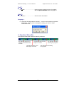
2. Licenses
(1) Nippon Avionics (hereinafter called "the Company") will offer you with
non-exclusive license of using the Software under the following terms:
①
The Software shall be used on the licensed number of computers.
Licensed number of computers: 1
②
If the software is read into temporary memory such as RAM, or installed
and used in fixed memory such as a hard disk, the use is regarded as
requiring the software license specified in this agreement.
3. Right of Reproduction
(1) You can make only one copy of the Software or install the Software onto a hard
disk and store the original as the back up only for the purpose of backing up or
storing it. In this case, this agreement shall apply to the copy and the Software
in the hard disk, which may not be used for any other purposes.
4. License
(1) All the rights concerning the software, excluding those defined explicitly in this
agreement, shall be possessed by The Company or the supplier, but shall not
be relocate or transferred to you explicitly or implicitly based on this agreement.
(2) You may not modify the contents of the Software or lend, lease, or transfer it.
5. Prohibition of Reverse Engineering
You may not reverse engineer, decompile, or deassemble the Software.
6. Warranty
(1) If a conflict such, as prohibition of use, notice of demand for compensation for
losses, or resort to legal action, is raised, arguing that the Software will breach
an intellectual property right such as a patent right, utility model right, right of
registered design, trademark right, or copyright (hereinafter called "intellectual
property right"), The Company will do its best to address and resolve the
conflict. If the Company failed in the resolution, or the amount of money
required for the resolution will exceed the rational range, the Company will offer
an alternative to you, or return the paid amount of money to you.
(2) If a disk or manual accompanying the Software contains a defect, the Company
will replace it with a non-defective version free of charge, provided that the
elapsed period will be within 1 year after delivery.
4
Advanced Package 1.1 User’s Manual
Nippon Avionics Co., Ltd. 2006
(3) The Company does not guarantee that the Software contains any problems,
such as errors or bugs. In any of cases including the above two paragraphs, the
Company will not take any responsibility for any damage that will be raised due
to use or unavailability of the Software, even if occurrence of the damage will
have been or be able to predicted.
(4) If the Company will take responsibility for compensation for losses, it will pay to
you up to the cost you will have paid for the Software to the Company
7. Cancellation of Agreement
(1) If you breach this agreement, the Company may be cancel part or the whole of
the agreement without any prior notice to you. In this case, you shall
immediately terminate and return the Software to the Company.
5
Advanced Package 1.1 User’s Manual
Nippon Avionics Co., Ltd. 2006
Table of Contents
Safety Precautions..................................................................................... 2
Notes ........................................................................................................... 3
Software License Agreement.................................................................... 4
INTRODUCTION ......................................................................................... 8
Software Features .........................................................................8
ThermoController.................................................................................... 8
PixCruiser ............................................................................................... 8
ThermoMovieEditor ................................................................................ 9
Applicable Thermography.............................................................9
PC System Configuration ............................................................10
OS (operating system).......................................................................... 10
PC Models ............................................................................................ 10
Installing AdvancedPacakge........................................................11
System Requirements ...........................................................................11
How to Install .............................................................................11
Uninstalling AdvancedPacakge....................................................20
Reinstalling AdvancedPacakge ....................................................20
Application Programs to Be Installed ..........................................20
About an installation disk ...........................................................20
About Reinstallation of Driver.....................................................21
Instruction of ThermoController............................................................. 24
Basics of Use ..............................................................................24
Initial Screen...............................................................................25
1. Menu Bar .............................................................................26
File(F) ................................................................................................... 26
Command(C) ........................................................................................ 26
View (V) ................................................................................................ 26
Record/Play Back(R) ............................................................................ 26
Tool(T)................................................................................................... 27
Help(H) ................................................................................................. 27
Language ............................................................................................. 27
2.
Operation Status Bar ............................................................27
3.
TVS Menu ............................................................................28
4.
Image Choosing Button........................................................31
5.
Point Temperature Display ...................................................31
6.
Cursor Coordinates Display .................................................31
7.
Recording Mode...................................................................31
8.
Point Edit Button ..................................................................31
9.
Graph Display Area ..............................................................31
10. Status Bar ............................................................................32
11. Image Display Area ..............................................................32
12. Movie Playback/Recording Controller...................................32
13. Temperature Display Controller ...........................................33
14. TVS Controls ........................................................................33
6
Advanced Package 1.1 User’s Manual
Nippon Avionics Co., Ltd. 2006
15. Capture Button ....................................................................33
16. Recording Playback Information Display...............................34
Environment Settings Window.....................................................34
Options Window.................................................................................... 34
Recording Settings ............................................................................... 40
Instruction of PixCruiser ......................................................................... 41
1. Main Functions ....................................................................41
2. Basic Operations ..................................................................41
Main Windwow...................................................................................... 42
Folder Manipulation .............................................................................. 43
File Manipulation................................................................................... 43
Browse a folder or file........................................................................... 44
Calendar Operation .............................................................................. 45
Enlarged view (preview) ....................................................................... 46
3.
Environment Settings ...........................................................47
Associating applications ....................................................................... 47
Display attribute .................................................................................... 48
Display folder ........................................................................................ 49
Infrared image color palette.................................................................. 50
Enlarged View....................................................................................... 51
4.
Menu Bar .............................................................................51
File(F) ................................................................................................... 51
Display(V) ............................................................................................. 51
Set(S).................................................................................................... 51
Help(H) ................................................................................................. 51
Language.............................................................................................. 51
5.
Protected .............................................................................51
Instruction of ThermoMovieEditor ......................................................... 52
Key Features...............................................................................52
Basic Operation ..........................................................................53
Menu Bar .............................................................................................. 53
Control Field Window ........................................................................... 58
Time Scale ............................................................................................ 59
Edit Animation Area .............................................................................. 60
Graph Area ........................................................................................... 62
Editing Animation Image Data ....................................................63
Deleting Unnecessary Head Frames.................................................... 63
Unifying Two Animation Images ........................................................... 63
Changing the Frame Rate .................................................................... 64
Saving Still Image Data ........................................................................ 64
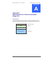
Appendix 1 Specifications for Thermal Animation Image File.......... 65
File Structure ..............................................................................65
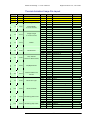
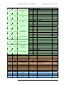
Thermal Animation Image File Layout .........................................66
List of User Tags ................................................................................... 68
Animation Image File Type ................................................................... 68
Image Recording Format...................................................................... 68
Point Information................................................................................... 68
Alarm Condition .................................................................................... 69
Chapter Information.............................................................................. 69
Animation Data Division Format ........................................................... 70
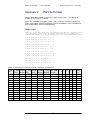
Appendix 2
CSV File Format .............................................................. 72
7
Advanced Package 1.1 User’s Manual
Nippon Avionics Co., Ltd. 2006
Chapter
1
INTRODUCTION
Thank you very much for purchasing infrared image transfer tool Avio Advanced
Package. Avio Advanced Package enables infrared and visible images to be
transferred or controlled easily, and allows files to be managed by connecting it to
the infrared thermography TVS-500 through USB interface.
This package consists of three software items:
ThermoContoroller .......... TVS control tool
PixCruiser........................ Thermal image file management tool (browser)
ThermoMovieEditor......... Moving image playback/edit tool
Software Features
This package features the following:
ThermoController
ThermoController enables the following features by being interfaced with the
TVS-500 through USB:
Displaying and saving infrared images and visible image transfers in real time
Displaying a mixed image of infrared and visible images
Controlling TVS-500
Displaying the point temperatures (5 points)
Displaying a point temperature graph
Point temperature alarm
Sending an email to a mobile phone or similar terminal when an alarm occurs
Changing the display temperature range, display color, and temperature unit
PixCruiser
Displaying thermal and visible images in thumbnail form.
Copying, moving, and deleting a file
Displaying a daily folder tree
Customizing association with other software
8
Advanced Package 1.1 User’s Manual
Nippon Avionics Co., Ltd. 2006
ThermoMovieEditor
Playing back or editing the moving image file
Displaying the point temperature
Displaying a point temperature graph
CSV file output of the point temperature
Batch conversion of still image files (iri, jpeg, and bmp)
Export of moving image file (AVI file)
Applicable Thermography
This software applies to the following Nippon Avionics Infrared Thermography TVS
Series model:
TVS-500 (USB I/F model)
9
Advanced Package 1.1 User’s Manual
Nippon Avionics Co., Ltd. 2006
PC System Configuration
Install AdvancedPackage in a PC satisfying the following requirements:
OS (operating system)
Microsoft Windows 2000 SP-4 or later
Microsoft Windows XP SP-2 or later
If you install the accompanying software in the PC, you have to log on to it under the
privilege of the administrator.
PC Models
DOS/V machine. (not applicable to Apple Macintosh machines)
The machine must have the DOS/V software that is preinstalled, and
equipped with the USB 2.0 interface as a standard item.
CPU
Pentium M/1.7 GHz (or equivalent) or greater, or Pentium 4/
2.6 GHz or greater recommended
RAM
512 MB or more
HDD
Free space of about 1 GB or more
7200rpm or grater (in case of Thermal 60fps + Visual Image
simultaneously recording)
Display colors
16-bit color (65,536 colors) or more
Resource
XGA (1024x768) or more
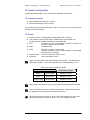
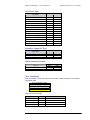
Higher recording frame rates require faster HDD rotation. The table below
shows the standard. Lower the frame rate when frame dropping occurs.
HDD rotate speed needed (3.5”HDD)
Image Recording
HDD Rotation speed
Thermal
Visual
60 fps
1 fps or grater
7200rpm or more
60 fps
Not Record
5400rpm or more
30 fps or less
20 fps or less
5400rpm or more
May not be connectable to any PC that contains an ATI USB Host Controller.
Even if it satisfies the above-mentioned specification, Nippon Avionics does
not guarantee that this software operates with all PCs.
When the USB hub was used, or when much USB equipment is connected,
transmission speed may become slow or it may not operate normally.
10
Advanced Package 1.1 User’s Manual
Nippon Avionics Co., Ltd. 2006
Installing AdvancedPacakge
System Requirements
IMPORTANT - These are the system requirements for proper installation of
AdvancedPackage on Windows 2000 or XP:
z
You should be an authorized System Administrator because you need to have
access to the registry domain that allows only those users who have authority.
(This is the requirement for installation. No authority is required for use of the
software.)
z
Your PC system configuration must be compatible with the Minimum PC
System Configuration described above.
z
Be sure to turn off the power to TVS-500 when you connect it to your PC for the
first time. (Refer to the method of “reinstalling the diver” shown from page 20
onwards if you tried to install the diver without turning off the power to TVS-500
and failed in installation.)
z
When you install in Japanese version OS, please install from the Japanese
folder of the attached installation disk instead of the USB memory of TVS-500
built-in.
How to Install
When installing the driver afresh, follow the procedure shown below. We
recommend the method shown below although the driver can be installed by some
other methods. Refer to “Reinstalling Advanced Package” on page 20 when an old
version has been installed or reinstalling the new version.
1
2
Start up your PC. Log on with the authority of System Administrator. Do not
connect TVS-500 as yet.
With the TVS-500 power switch OFF, connect it to your PC through a USB cable.
Upon connection, the device driver will start to run setup. If the Restart message
appears after the setup run is over, restart the computer.
Your computer may not restart if its CD drive has been set as the priority
starter drive over its HD drive. This happens because TVS-500’s built-in
memory is recognized by the computer as a CD-ROM. In this case,
disconnect the USB cable once or change the priority order of the drives.
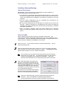
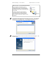
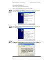
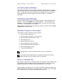
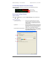
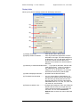
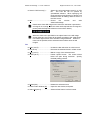
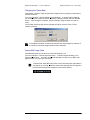
3
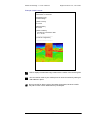
After a little while (about 30 seconds), the
launcher is automatically activated and will
appear on the screen as shown on the right.
Click the Install software button. (If you have
restarted the computer with the USB cable
connected as is in step 2 above, the launcher
is not automatically activated.)
If the launcher is not activated automatically,
follow the instructions given in the “When
launcher is not activated automatically” box.
Some PCs might have been set up not to allow automatic activation of
launchers. Also, pre-installation of CD/DVD writing software or
security-related issue could have caused no activation of the launcher.
11
Advanced Package 1.1 User’s Manual
Nippon Avionics Co., Ltd. 2006
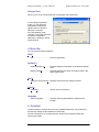
When launcher is not activated automatically:
When TVS-500 is connected to a PC, its
internal USB memory is recognized by the
computer as two drives: one as CD-ROM drive
[UD-ROM], and the other as removal disk drive
[TVS_USB].
You’ll find a “USB_APP” folder inside the
removable disk [TVS_USB] recognized as
above (located in your PC’s My Computer
icon). Open the “USB_APP” folder to run the
Setup.exe.
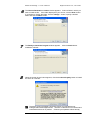
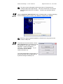
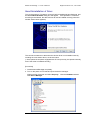
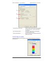
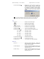
4
5
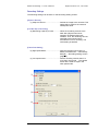
The installation window as shown below appears on the screen. After selecting a
language and click the Next> button. The computer will start setup operation.
The language you select here is used for the installation purpose only.
When the setup operation is done, the window as shown below will appear. Click
the Next> button.
12
Advanced Package 1.1 User’s Manual
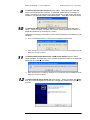
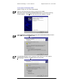
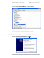
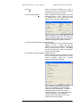
6
Nippon Avionics Co., Ltd. 2006
The Choose Destination Location window appears. Select a folder in which you
wish to install the file. If the folder displayed is your choice, click the Next> button.
If you desire to change the folder, click the Change… button, specify a desired
folder and click the Next> button.
7
The Ready to Install the Program window appears. Click the Install button.
Installation will start.
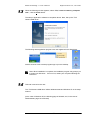
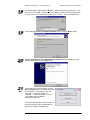
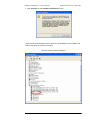
8
When the screen shown below appears, click the Continue Anyway button to install
the driver for TVS-500.
The above screen will appear, because the driver for TVS-500 has not
undergone Microsoft’s approval test. We have conducted an in-house test and
confirmed that there is no problem. Continue your operation without anxiety.
13
Advanced Package 1.1 User’s Manual
9
10
Nippon Avionics Co., Ltd. 2006
The Microsoft DirectX 8.1 Setup dialog box opens. When prompted, click Yes.
Since a license agreement screen etc. is displayed, please set up according to a
screen. This setup is not required if you have DirectX 8.1 or later version previously
installed in your Windows 2000 or XP-based system. Click No to cancel the setup.
The Microsoft .NET Framework 1.1 Setup (including service packs) dialog box
opens. When prompted, click Yes, then, since a license agreement screen etc. is
displayed, please set up according to a screen.
Installation is necessary even when you have .NET Framework 2.0 installed on your
computer.
11
※
Then, the installation screen of a service pack is displayed. Please install.
※
When the message of a reboot is displayed, it is not rebooted until all installations finish,
although it chooses to reboot.
The Microsoft Windows Media Video 9 VCM Codec Setup dialog box opens.
When prompted, click Yes, then, since a license agreement screen etc. is displayed,
please set up according to a screen.
※
12
When the message of a reboot is displayed, it is not rebooted until all installations finish,
although it chooses to reboot.
The Microsoft XML Parser Setup dialog box opens. When prompted, click Next>,
then, since a license agreement screen etc. is displayed, please set up according to
a screen.
14
Advanced Package 1.1 User’s Manual
13
Nippon Avionics Co., Ltd. 2006
When the following window appears, select “Yes, I want to restart my computer
now.”, click the Finish button.
The setup of application software is completion above. Next, Set up the "TVS
Camera USB driver".
The following three application programs are now registered in the Start Menu.
And the shortcut icons to these programs pop up on the desktop.
Note: When installation is complete, the installation program may prompt you
to restart your Windows. If this occurs, restart your computer following the
instruction.
14
TVS-500 is turned on the next.
The "TVS Camera USB driver" differs Windows 2000 and Windows XP in the setup
method.
(In the case of Windows XP, the following page is followed, and, in the case of
Windows2000, page 18 is followed)
15
Advanced Package 1.1 User’s Manual
Nippon Avionics Co., Ltd. 2006
In the case of Windows XP
(Refer to Page 18 in the case of Windows2000)
Now turn the TVS-500 power switch on (and connect USB).
15
Win XP
16
17
The Found New Hardware Wizard will launch and the following window appears.
Select “No, not this time.” Click Next> to proceed with the installation.
Select Install the software automatically (Recommended) as shown below, and
then click the Next> button.
The Hardware Installation dialog box as shown below opens. Click the Continue
Anyway button to proceed with the installation of the device driver for TVS-500.
16
Advanced Package 1.1 User’s Manual
Nippon Avionics Co., Ltd. 2006
The above screen will appear, because the driver for TVS-500 has not
undergone Microsoft’s approval test. We have conducted an in-house test
and confirmed that there is no problem. Continue your operation without
anxiety.
18
Win XP
When the Hardware Update Wizard window is displayed with a message indicating
that the installation was successful. Click Finish to complete the installation.
Some PCs require repeated registration of the driver as many times as the
number of USB ports.
19
Win XP
To activate the ThermoController, click the
Run a program button of the launcher (see
the illustration on the right), or from the
Start Menu, choose All Programs →
TVS-500 → ThermoController. Or you
may double-click the desktop
ThermoController icon.
The ThermoMovieEditor and Pixcruiser can
be launched either from the Start Menu or
by double-clicking the desktop icon.
17
Advanced Package 1.1 User’s Manual
Nippon Avionics Co., Ltd. 2006
In the case of Windows 2000
15
Win
16
(Refer to Page 16 in the case of WindowsXP
Now turn the TVS-500 power switch on (and connect USB).
Welcome to the Found New Hardware Wizard will launch and the following
window appears. Click Next> to proceed with the installation.TVS-500
Select Search for a suitable driver for my device (Recommended) as shown
below, and then click the Next> button.
Win
17
Win
If Locate Driver Files screen is displayed, after attaching a check mark for
Specifying a Location, the Next> button will be pushed.
18
Advanced Package 1.1 User’s Manual
18
Win
19
Nippon Avionics Co., Ltd. 2006
On the following screen Push the Browse… button and specify a driver file. The
driver file is TVS_USB. Specify the Drivers folder of a drive. (The following screen
is TVS_USB. It is the case where a drive is an G: drive) Then push O.K button.
On the following Driver Files Search Results screen, push the Next> button.
Win
20
Win
21
Win
When Completing the Found NewHardware Wizard screen is displayed, Push
Finish button and it is an installation end.
To activate the ThermoController, click the
Run a program button of the launcher (see
the illustration on the right), or from the
Start Menu, choose All Programs →
TVS-500 → ThermoController. Or you
may double-click the desktop
ThermoController icon.
The ThermoMovieEditor and Pixcruiser can
be launched either from the Start Menu or
by double-clicking the desktop icon.
19
Advanced Package 1.1 User’s Manual
Nippon Avionics Co., Ltd. 2006
Uninstalling AdvancedPacakge
After opening the Add or Remove Programs tool in the Control Panel icon, select
“TVS-500” from the list of currently installed programs and then click on the Remove
button. Follow the instructions on the screen to complete removing the program.
The middleware will not be uninstalled by the above operation. Uninstall it
individually.
Reinstalling AdvancedPacakge
Click the “Install software” button of the program launcher, and the installer will be
activated. Click the CHANGE button to start installation. This method permits
installation of ThermoController, ThermoMovieEditor, Pixcruiser, and TVS Camera
USB driver. The middleware is not installed.
When installing all the programs, uninstall all the programs and then click the Install
software button of the launcher.
Application Programs to Be Installed
This installer is used to install the following software:
Microsoft .NET Framework 1.1
Microsoft .NET Framework 1.1 Service Packs
Microsoft Windows Media Video 9 VCM
Microsoft Direct X 8.1
Microsoft XML Server Setup
AdvancedPackage ThermoController
AdvancedPackage ThermoMovieEditor
AdvancedPackage Pixcruiser
TVS Camera IUSB Driver
The USB driver is saved in the Drivers folder of the TVS_USB drive.
The installer for AdvancedPackage is the Setup.exe located in the Setup
folder inside the AVIO_APP folder of the TVS_USB drive.
About an installation disk
Two installers, Japanese (JP) and English (EN), are contained in the installation disk.
The Japanese version installer is saved in the USB memory in TVS-500, and the
English-language edition installer is saved beforehand at it of TVS-500E.
When the data in the USB memory of TVS-500 is deleted accidentally, please copy
all folders and files in EN folder in an installation disk, or JP folder to the "TVS_USB"
drive (in USB memory of TVS-500) using Windows Explorer etc.
20
Advanced Package 1.1 User’s Manual
Nippon Avionics Co., Ltd. 2006
About Reinstallation of Driver
Turn on the power to TVS-500 to connect it before installing AdvancePackage, and
the Found New Hardware dialog box will appear. If the operation is continued
according to the Wizard, the device driver will not be installed correctly (when the
window shown below appears).
The corrective measures to take when the device driver is not installed correctly,
including the case shown above, are shown below.
(* Some personal computers equipped with ATI’s chip set may not operate normally
even if the driver is installed correctly.)
[Procedure]
1. Install AdvancedPackage completely.
2. Turn on the power to TVS-500 and open the device manager.
(Right-click My Computer and select Property. Click the Hardware tab and
click Device Manager.
21
Advanced Package 1.1 User’s Manual
Nippon Avionics Co., Ltd. 2006
3. There should be Unknown USB device. Select and delete it.
4. Turn off the power to TVS-500 once and then turn it on again.
5.
Found New Hardware Wizard will appear. Select and execute Automatic detection.
6. Check Automatically install software and click Next>.
22
Advanced Package 1.1 User’s Manual
Nippon Avionics Co., Ltd. 2006
7. Click Continue on the Hardware Installation window.
The driver has been installed correctly when the TVSUSB device is included in the
USB device group of the device manager.
〈Normal screen of device manager〉
23
Advanced Package 1.1 User’s Manual
Nippon Avionics Co., Ltd. 2006
Chapter
2
Instruction of ThermoController
Basics of Use
1. Start the TVS and PC.
Fix the range of TVS to L or H according to a measurement thing.
2. After ThermoController has started, connect the TVS and USB using the USB
cable.
3. The launcher starts automatically.
4. If you are making the connection to your PC first, press the Install Software
button to install AdvancedPackage first. (For the installation procedure, see the
INTRODUCTION on page 8.)
5. If the software has already been installed, press the Run a Program button to
start the software. If the software does not start automatically, select
TVS-500→ThermoController in the Windows Start menu.
6. The Initial Window (detailed later) appears.
The software may not start automatically, depending on the environment of
your PC. If it does not start, contact the system administrator.
If you connect TVS and PC through USB interface, the drive system is
recognized as consisting of two drives even if power to the TVS is off. Before
removing the connection, remove the appropriate drive according to the
instructions in "Removing the Hardware Safely".
The file containing moving images recorded are temporarily saved in the
folder that was specified in the Working Directory common tab (Tool→
Environment Settings).
ThermoController does not support range switching. We recommend you to
use fixing a range. Please reboot ThermoController, when a range is changed
during ThermoController starting.
24
Advanced Package 1.1 User’s Manual
Nippon Avionics Co., Ltd. 2006
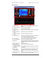
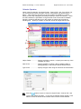
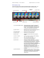
Initial Screen
①
②
③
④
⑭
⑪
⑤
⑬
⑥
⑦
⑧
⑫
⑮
⑯
⑨
(2) Operation Status Bar
Allows you to set up the language, environment, and
others.
Shows the status by animation.
(3) TVS Menu
Allows various TVS settings.
(4) Image Switching
Button
Switches between the thermal, visible, mixing images.
(5) Point Temperature
Display
Displays up to five point temperatures.
(6) Cursor Coordinates
Display
Shows the coordinates of the cursor.
(7) Recording Mode
(8) Point Edit button
Shows the current recording mode. It is recorded in the
mode currently displayed here next time.
You can switch the mode by double-clicking here.
Adds, moves, or deletes a measurement point.
(9) Graph Display Area
Shows the point temperature graph.
(10) Status Bar
Shows the applicable model, the current image transfer
speed, the status/error, and the remaining amount of
hard disk.
Image display area
(1) Main Menu Bar
(11) Image Display Area
(12) Movie Playback/
Recording Controller
Plays back or records moving images.
(13) Temperature Display
Controller
Sets the display temperature range. Also changes the
color palette.
(14) TVS Control
Performs the same function as the TVS function button.
(15) PC One-Shot
Recording Button
When you press this button, the current image is
recorded in the form of a static image in the specified
folder.
Shows the number of frames, the current time, and the
elapsed time during recording/playback.
(16) Recording Playback
Information
25
Advanced Package 1.1 User’s Manual
Nippon Avionics Co., Ltd. 2006
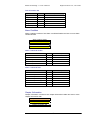
1. Menu Bar
File(F)
Save Recording File ...........Saves the recorded file.
Save in CSV Format...........Saves the point temperature trend as a CSV file.
Exit Application ...................Exits ThermoController.
Command(C)
Connect ..............................Initiates connection to the TVS through USB
interface. Usually connected automatically when
ThermoController starts.
View (V)
Graph Display (G)...............Turns ON/OFF the graph display.
Record/Play Back(R)
····· Play
back ...................................... Plays back the last moving image
recorded after the start.
····· Normal
····· Alarm
Recording......................... Starts normal recording.
Recording........................... Starts alarm recording.
····· Stop
.............................................. Stops playback/recording. Also switches
the TVS to its live image.
····· Next
Frame................................... Plays back the next frame during PAUSE.
····· Previous
····· Fast
Frame ............................ Plays back the previous frame during
PAUSE.
Forward/ Slow Playback ….. Plays back images at a speed of 1/60 to
60 times.
····· Recording
Setting Screen ............ Sets the frame rate for recording. Select
a rate, and the setting screen will appear.
For details, refer to page 40
• For the high speed mode, specify the
number of frames per second.
• For the low speed mode, specify the
time interval recorded, in 1 s increments,
from 0 h, 0 min, 1 s to 24h, 59 min, 59 s.
26
Advanced Package 1.1 User’s Manual
Nippon Avionics Co., Ltd. 2006
Tool(T)
Option.. .............................Opens the option settings window. For details,
see the Options Window section on page 34.
Help(H)
Version .. ...........................Shows version information.
Language ..
Opens the language selection window. You can choose between Japanese
and English. After you have changed the setting, you have to restart
ThermoController.
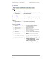
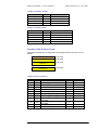
2. Operation Status Bar
The Operation Status Bar shows the status by animation.
This indicates that the PC is
currently connected with the
TVS-500.
This indicates that a moving
image is on-screen.
This indicates that the TVS
live image is on-screen.
27
This indicates that alarm
recording is in progress.
This indicates that recording
is in progress.
Advanced Package 1.1 User’s Manual
Nippon Avionics Co., Ltd. 2006
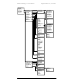
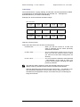
3. TVS Menu
The operation is the same as that for the Avio logo menu of TVS. (Refer to the
menu system shown below.) Refer to the Instruction Manual for the TVS for the
detailed usage.
MEASURE
SCOPE
DISPLAY
SYSTEM
CONFIG
POINT
EMIS
UNIT
MAX/MIN
AREA
POINT1
POINT2
POINT3
POINT4
POINT5
E=
TA
P-EMIS
C
F
K
MAXTEMP
MINTEMP
MARK
OFF
ON
OFF
MOVE
CENTER
X-Y
EMIS
SENSOR
INPUT
POINT1
POINT2
POINT3
POINT4
POINT5
ALL
ON
OFF
LARGE
SMALL
VARIABLE
SET
SCALE
RANGE
AVERAGE
AS
AP
FULL
SPAN
LEVEL
HIGHTEMP
LOWTEMP
PPM
R&D
ME
AUTO
LOW
HIGH
OFF
2
4
8
16
28
SINGLE
CONTINUE
E1=
T1=
GLOBAL
GLOBAL
POINT
Advanced Package 1.1 User’s Manual
MEASURE
SCOPE
DISPLAY
SYSTEM
CONFIG
Nippon Avionics Co., Ltd. 2006
COLOR
ISOTHERM
ZOOM
FREEZE
SCROLL
ICON
LCDBRIGHT
GRID
DISPLAY
PALETTE
GRADATION
ON
OFF
HIGH
LEVEL
LOW
BGCOLOR
COLOR
OFF
X2
X2MOVE
X4
X4MOVE
ON
OFF
RAINBOW
HOTWHITE
HOTBLACK
HOTIRON
IRONBOW
CONTRAST
256
16
8
4
RAINBOW
HOTWHITE
HOTBLACK
HOTIRON
IRONBOW
CONTRAST
RAINBOW
RED
WHITE
BLACK
DATE
TIME
EMIS
AMBITEMP
FILENAME
MEMO
AVE
BAT
TABLEINF
ALARM
ON
OFF
ON
OFF
NORMAL
REVERSE
DATE/TIME
VIDEOOUT
CURSOR
EDITMOMO
WINK
SETDATE
SETTIME
NTSC
PAL
SPEED
AUTO
INTERVAL
OFF
WINK
29
FAST
MEDIUM
SLOW
Advanced Package 1.1 User’s Manual
Nippon Avionics Co., Ltd. 2006
CONFIG menu
Look at the TVS screen when operating the TVS menu.
30
Advanced Package 1.1 User’s Manual
Nippon Avionics Co., Ltd. 2006
4. Image Choosing Button
Pressing this button switches between the thermal, visible, mixing images. If a
moving image displaying only thermal images is being played back, the thermal
image button is only displayed.
·········Thermal image is displayed
·········Visible image is displayed.
·········Mixing image is displayed.
5. Point Temperature Display
This software can display up to five point temperatures .
6. Cursor Coordinates Display
This shows the coordinates of the cursor. X: 0 to 319, Y: 0 to 239
7. Recording Mode
This shows the current recording mode. You can switch the mode by double-clicking
here.
8. Point Edit Button
Used to add, move, or delete the measurement point. Press this button before
specifying the point.
Addition
Movement Deletion
9. Graph Display Area
The trend graph of the point temperature is displayed in this area
31
Advanced Package 1.1 User’s Manual
Nippon Avionics Co., Ltd. 2006
10. Status Bar
Shows various related information items.
Applicable
model
Status and error
Remaining amount of HD
Current image transfer speed (fps)
(Note: The background turns yellow when there are some frames that could not be received.)
11. Image Display Area
This shows operation information including PLAY, REC, and PAUSE in Image
Display Area.
12. Movie Playback/Recording Controller
Plays back or records the movie.
Stops playback/ recording.
Play back/Pause
Return/ Advance
Previous Frame
FF / Slow
Playback
Recording
Alarm recording
Playback Slider
Saves Recording File ..
Recording Setting
Window ..
Save Recording File.. ................. Pressing this button displays the save window.
Specify the folder to save. Then, specify the file
name. The moving image file is saved under a
name with extension .IRM.
Recording Setting Window... ..... Allows you to set up the recording conditions.
For details, see the Recording Settings on page
40.
32
Advanced Package 1.1 User’s Manual
Nippon Avionics Co., Ltd. 2006
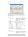
13. Temperature Display Controller
Sets the display temperature range. You can change the color palette.
(1) Maximum temperature
(4) Maximum display
temperature
(6) Display temperature
scale
(3) Display Temperature
Slider
(2) Minimum temperature
(5) Minimum display
temperature
(7) Unit Switcher (C/F/K)
(8) Temperature scale
(1), (2) Maximum/minimum
temperatures
Double-clicking the numeric field allows you to
change it by typing the new value from the
keyboard.
(3) Display temperature
slider
Dragging the slider allows you to change the
display temperature (4), (5), (6). By dragging
the color bar section of the slider, you can slide
the display temperature range with the display
temperature width unchanged. You can also
change the maximum (4) or minimum display
temperature (5) by dragging the upper and
lower button on the color bar.
(4), (5) Maximum or
minimum display
temperature
Double-clicking the numeric field allows you to
change it by typing the new value from the
keyboard.
(6) Display temperature
scale
Displays the scale automatically with the
minimum to maximum display temperature
range divided into eight segments
(7) Unit Switcher
Allows you to switch the temperature unit
between C, F, and K.
14. TVS Controls
These controls are used to perform the same function as the TVS function button.
For details, refer to the TVS instruction manual.
15. Capture Button
The image when this button is touched is recorded as a still image in the specified
folder. Select TOOL (T), OPTION (O), and Capture on the common setting tab to
specify the folder. When no folder is specified, an error message will appear.
Capture Button
33
Advanced Package 1.1 User’s Manual
Nippon Avionics Co., Ltd. 2006
16. Recording Playback Information Display
Shows the number of frames, the current time, and the elapsed time during
recording/playback.
Frame number
Time of recording
Elapsed time of recording
Environment Settings Window
Options Window
Select Tool→ Options (O)... to open the Option Settings window, detailed later.
Common Settings tab
(1) Working Directory·····················Specify the working folder that is used by
ThermoController. The Windows temporary
folder is usually "%USERPROFILE%¥Local
Settings¥Temp".
(2) Capture·····································Specify the folder and palette in which to save
the image data with the ThermoController PC
REC button. If you do not have any folder or
palette, an error message will appear.
(3) Confirmation during starting ·····Allows you to select whether or not to display
the message dialog that recommend to fix the
range switching during startup.
①
②
③
34
Advanced Package 1.1 User’s Manual
Nippon Avionics Co., Ltd. 2006
Alarm Setting Tab
(1) Condition of Combination·············· Set either AND or OR for the condition of
each point.
(2) Point Condition ······························ Set the condition of each point. The
following setting is possible for each point.
The details are explained on the next
page.
(3) Alarm Recording Mode·················· Specify the repeat recording mode or
one-time recording mode.
Repeat recording mode: Images are
recorded without limit whenever the alarm
condition is met.
One-time recording mode: Images are
recorded only during the initial period
when the alarm condition is met.
(4) Before-After Recording Setting ····· Specify the number of preceding recorded
frames and the number of stopping frames
during recording.
Number of preceding recorded frames: Set
the number of preceding recorded frames
that exist before the alarm condition is met.
Number of stopping frames during
recording: Set the number of recording
frames that exist after the alarm condition
is not met.
(5) Transmitting Alarm Mail················· Check this to send an alarm mail.
(6) Transmission Standby Time ·········· Set the time during which no alarm is
considered to be given even if the alarm
condition is met.
①
②
③
④
⑤
⑥
35
Advanced Package 1.1 User’s Manual
Nippon Avionics Co., Ltd. 2006
Point Conditions
(2)
(3)
(4)
(5)
(6)
(1)
(1) Observe......................... Specify whether the point should be enabled or
disabled. First, enable ({) points required to
output an alarm.
(2), (3) Condition 1.............. In the (3) field, set “Not used,” “Greater than or
equal to,” or “Less than or equal to.” If you specify
“Not used,” “-“ will be displayed in the “Condition”
field, which will disable you to set the temperature.
In the (2) field, set the condition temperature.
(4) AND/OR......................... Specify AND or OR for Condition 1 and Condition 2
for each point.
(5), (6) Condition 2.............. Same as (2) and (3)
Indicates Enabled/Disabled by the color of the background. White indicates
Enabled, and gray Disabled.
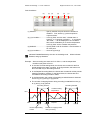
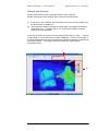
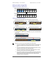
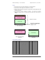
Example: Alarm recording was set at 35°C for Point 1, and the temperature
transition took place at Point 1.
In the One-Time Recording Mode, the frames are recorded for the first
period satisfying the alarm condition. In the figure below, the frames are
thus recorded only for Recording Period A.
In the Repeat Recording Mode, the frames are recorded for all the periods
satisfying the alarm condition. In the figure below, the frames are thus
recorded for Recording Periods A and B.
In the figure below, the number of preceding recorded frames is obtained
from the (1) to (2) and (5) to (6) periods.
The number of stopping frames during recording is obtained from the (3)
to (4) and (7) to (8) periods.
Recording Period A
Recording Period B
Condition setting
temperature
35°C
Point 1 temperature transition
Elapsed
Start
(1) (2)
Number of preceding
frames
(3) (4)
(5) (6)
Number of stopping frames
during recording
36
(7) (8)
Advanced Package 1.1 User’s Manual
Nippon Avionics Co., Ltd. 2006
Mail Content Settings tab
Allows you to set up the contents of the mail to be sent in response to an alarm.
(1) Mail Item & Title Settings..........Click the check boxes associated with the
items that are to be included in the mail. All
the items associated with the check marks will
be inserted into the mail. You can change any
title by double-clicking the appropriate "Title to
Display" field. Also, see the Example of Mail
Contents on page 39.
(2) Signature ..................................You can add a signature (text only) to the
mail.
(3) Image Attached ........................Allows you to set whether the image at time of
the alarm be attached to the mail. If you
check on "Attach a palette sample", this will
generate an image that contains the
temperature scale attached on the right of the
image.
(1)
(2)
(3)
37
Advanced Package 1.1 User’s Manual
Nippon Avionics Co., Ltd. 2006
Mail Send Settings tab
This tab allows you to set up the conditions for sending a mail in response to an
alarm.
(1) Destination .................... Set the subject, destination, CC, and BCC of the
mail to send. You can send the same mail to up to
four destinations that are specified in different lines.
(2) Mail Account .................. Specify the originating SMTP mail server and e-mail
address. When authentication by the server is
necessary, check “Authentication necessary” and
set the POP3 server name, account name, and
password. You can send the mail with the current
settings through the Sending Test button. After
pressing the Sending Test button, check that the
mail has arrived at the destination.
(3) Method .......................... Specify the method of connection to the Internet. If
you select LAN Connection, the connection will be
established according to the settings on the PC. If
you select Dial-Up Connection, set Destination,
User Name, Password, and Timeout Period (s). If
you select the destination, the dial-up connection
name on Windows will be displayed. If it will not be
displayed, complete the Windows dial-up settings
first.
By a dialup connection, when you use it by a pulse line, please attach P before
a telephone number. Example P03-5436-XXXX
(1)
(2)
(3)
38
Advanced Package 1.1 User’s Manual
Nippon Avionics Co., Ltd. 2006
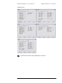
Example of Mail Contents
[Alarm Title]
2006/06/25 14:26:08.528
[RecordingType]
Thermal Image
[Alarm Content]
P1 35.98
[Measurement]
P1 35.98
[Alarm Condition]
Condition of Combination AND
P1 => 35.00
-----------------------------------(Contents of Signature)
------------------------------------
How to display the attached image varies with the mailer of the receiving end.
You can receive mails at your mobile phone in various locations by setting its
mail address in place.
Do not use this for alarm notice of important phenomena, because e-mails
may fail to reach or their distribution may be delayed.
39
Advanced Package 1.1 User’s Manual
Nippon Avionics Co., Ltd. 2006
Recording Settings
The following settings can be done on the Recording Setting screem.
[Object to Record]
(1) Object to Record ................................ Selects the image to be recorded. This
setting will be used for the next and
subsequent starts.
[Forcible Stop of Recording]
(2) Remaining Capacity of Hard .............. When the remaining amount of the
hard disk (HD) has went short,
operation of Windows becomes
unstable. Thus, the remaining amount
specified herein should not be
exceeded for use for recording. The
initial setting is 500 MB.
[Frame Rate Setting]
(3) High-speed Mode ······························· Sets the recording frame rate. For
details, see Menu Bar → Record/Play
Back(R) → Recording Setting Screen
(page 26).
(4) Low-speed mode································ Set the recording interval when it is
more than one second. The camera
frame rate is fixed at 10fps in the
slow-speed mode.
①
②
③
④
40
Advanced Package 1.1 User’s Manual
Nippon Avionics Co., Ltd. 2006
Chapter
3
Instruction of PixCruiser
(Thermal Image File Browser)
1. Main Functions
PixCruiser is a file browser that can display thermal image files IRI and IRM, and
popular image files, such as JPG and BMP, in thumbnail form. The main functions of
PixCruiser are as follows:
Folder manipulation ........................ Creates a new file, and copies, moves,
renames, and deletes a file.
File manipulation ............................ Copies, moves, renames, and deletes a
file.
Folder display ................................. Displays the hierarchy of folders.
Calendar display............................. Displays trees for each year/month/day.
File display...................................... Displays an image file in thumbnail form.
The thumbnail images can be resized.
This function is available for the following
files:
Thermal image: IRI, IRM,
Ordinary image: BMP, JPG, TIFF,
File attribute display........................ Displays the attribute of the file you
selected.
Display refresh................................ Refresh the selection folder tree item
and file list to the latest status.
Association with the application ..... You can select the desired file to start the
application.
2. Basic Operations
PixCruiser allows you to move, copy, and delete a file or folder by the same
operations as Explorer.
PixCruiser cannot be subjected to multiplex starts
41
Advanced Package 1.1 User’s Manual
Nippon Avionics Co., Ltd. 2006
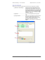
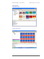
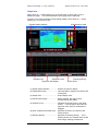
Main Windwow
Folder display window
Calendar display window
42
Advanced Package 1.1 User’s Manual
Nippon Avionics Co., Ltd. 2006
Folder Manipulation
To manipulate a folder, you can select the menu item by right-click and perform Drag
& Drop. Some short cut keys (Ctrl+C, Delete, etc.) are also available.
Drag & Drop is available also for either folder move or copy between PixCruiser and
Explorer.
Create a New Folder
To create a new folder, right-click the folder you desire to create, and then select
New→ Folder. The new folder is created under the name of "New Folder".
If another "New Folder" already exists, a serial number will be appended to the
folder name.
Copy a Folder
Select and right-click the source folder in the folder tree. After selecting Copy, select
and right-click the destination folder in the folder tree. Then select Paste.
Alternatively, perform Drag & Drop to copy the specified folder. The folder is copied
by pressing the Ctrl key concurrently.
While you are performing Drag & Drop, the folder cannot be copied within the
same list.
Folder copy is not enabled with any short cut key.
Move a Folder
Select and right-click the source folder in the folder tree. After selecting Cut, select
and right-click the destination folder in the folder tree. Then, select Paste.
Alternatively, perform Drag & Drop to move the specified folder.
Rename a Folder
Select and right-click the desired folder in the folder tree. Then, select Rename to
enter the edit mode.
Rename the folder. Then, click in any location other than the selected item (or press
the Enter key) to complete the renaming process.
Delete a Folder
Select and right-click the desired folder in the folder tree. Then select Delete. As a
result, the folder moves into the Trash.
File Manipulation
To manipulate a folder, you can select the menu item by right-click and perform Drag
& Drop. This is enabled also by pressing key(s) Ctrl+C or Delete. Note that the Ctrl
key is available for copy during Drag & Drop, but the Shift key is not available for
move during Drag & Drop.
File move and copy by Drag & Drop is enabled also between PixCruiser and the
Explorer.
43
Advanced Package 1.1 User’s Manual
Nippon Avionics Co., Ltd. 2006
Copy a File
Select and right-click the source file. After selecting Copy, select and right-click the
destination folder. Then select Paste.
Alternatively, perform Drag & Drop to copy the specified file. The folder is copied by
pressing the Ctrl key concurrently.
You can also use short cut key combination Ctrl+C and Ctrl+V to copy a file.
While you are performing Drag & Drop, the folder cannot be copied within the
same list.
Move a File
Select and right-click the source folder. After selecting Cut, select and right-click the
destination folder. Then, select Paste.
Alternatively, perform Drag & Drop to move the specified folder.
You can also use short cut key combination Ctrl+X and Ctrl+V to move a file.
Rename a File
Select and right-click the desired file. Then select Rename to enter the edit mode.
Click in any location other than the selected item. (or press the Enter key) to
complete the renaming process.
Delete a File
Select and right-click the desired. Then select Delete. This is enabled also with the
Del key.
With the environment settings, you can inhibit the delete function from being
available. See Page 49.
The calendar display window permits Cut and Copy, but it does not permit
Rename, Delete, and Paste.
Browse a folder or file
You can browse a folder in the folder tree.
You can single-click a "+" in the tree, or select and double-click a folder to expand
the list of subfolders.
To collapse the "-" sign in the tree, or select and double-click a folder to collapse the
expanded list of subfolders.
You can collapse the list of subfolders also by right-clicking and then selecting
Develop or Fold.
The calendar display window permits almost the same operation.
To browse a file, select the folder in the folder tree.
You can resize the thumbnail images using the slide bar.
44
Advanced Package 1.1 User’s Manual
Nippon Avionics Co., Ltd. 2006
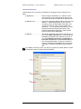
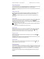
Calendar Operation
When using the calendar, set “Object Folder,” “Date of File,” and “Type of File” ((2),
(3), and (4) shown below), and then click the “Tree Display” ((5) shown below)
button. After searching according to the set condition, the folders ((1) shown
below) for each day will appear, permitting browsing of folders of each day. When
the entire hard disc is specified or a large number is set for the search subfolder
hierarchy, searching will take time or the number of images may exceed the
handling limit. Specify a condition so that the number of images will be small.
①
②
③
④
⑤
Object Folder .................. Specify the folder to search, or specify the hierarchy of the
subfolder to search.
Date of File ..................... Specify the date of creation, date of updating (date of
photographing), or the period of the file date to search.
Type of File ..................... Specify the type of file using an extension as shown below.
Click the
button to open or close the “Object Folder,” “Date of File,” and
“Type of File” setting windows. In the case of calendar display window, a red
frame is shown for the IRI file and a blue frame is shown for the IRM file.
45
Advanced Package 1.1 User’s Manual
Nippon Avionics Co., Ltd. 2006
Enlarged view (preview)
Double-clicking the file open the preview window of the image file.
Double-clicking the preview window clicks closes the preview window.
(1) In the case of IRI or IRM file, the coordinates of the mouse cursor position and
the temperature are displayed.
(2) The temperatrue display controller permits change of the display temperature
and display color. For detail, refer to “13. Temperature Display Controller”
(p.25) of ThermoMovieEditor.
In the case of the IRI file, right-click on the image and the specify “Send” → “Convert
To Still Image” to convert the file into a JPEG or BMP file. However, the change of
the display temperature range by the temperature display controller for image saving
will not be reflected. The image will be saved within the original display
temperature range.
①
②
46
Advanced Package 1.1 User’s Manual
Nippon Avionics Co., Ltd. 2006
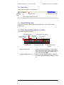
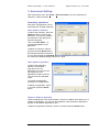
3. Environment Settings
After selecting the menu bar, Set(s) > Set environment, you can customize the
software in various manners.
Associating applications
More than one application can be
associated with a single expansion.
Add or Delete an Extension
To add a new extension, press the
Addition button to insert a new
blank item. (Line No.5 is added in
the example on the right figure.)
Enter the extension.
Then, press SET Detail… to
proceed with addition of the
application.
To delete an extension, select it,
and then press the Delete button.
By selecting the desired extension
to copy and pressing the Copy/Add,
the contents of detailed settings will also be copied.
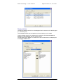
Add or Delete an Application
To add a new application,
select it from the blank
drop-down list. If the
application is not found in the
list, register the next
application to add it to the list.
You can enter the selectable
mode.
To register the application,
press the List of Applications.
To delete an application, select
it, and then press the Delete
button.
Register or Delete an Application
Press the Add button in the window below. A new line is added, which allows you to
register an application. You can type the application name as desired. Specify the
full path of the desired application to add.
To delete an application extension, select it, and then press the Delete button.
47
Advanced Package 1.1 User’s Manual
Nippon Avionics Co., Ltd. 2006
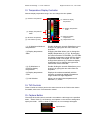
Display attribute
The item the attribute of which is to be displayed can be set for each of the file types
(i.e., attribute types).
The available attribute type and attribute are fixed. Nothing can be added.
To add or delete an item in the window below, select the item between Items to
Display and List of Items, and then click the arrow.
You can select Large, Medium, or Small for the size of characters to be displayed in
the Display attribute area.
48
Advanced Package 1.1 User’s Manual
Nippon Avionics Co., Ltd. 2006
Display folder
Allows you to perform settings related with file display and others.
(1)
(2)
(3)
(4)
(5)
(6)
(1) Display all the files .......................Lists up all the file in the file area.
(2) Specify retrieve conditions ...........Lists only the files the expansions of which
are listed on the right. The initial settings are
as listed there. You can add other extensions
to the list, however, the files that can be
displayed in thumbnail form will be limited in
that case.
(3) Hierarchy of retrieved subdirectories……If you specify the folder, the file under
it will also be listed. If this is 0, the files in
any subdirectory will not be listed. If the
setting is 1 (or 2), all the files 1 (or 2) levels
downward in the hierarchy will be listed.
(4) Order to display thumbnails .........Specifies how the files be sorted.
(5) Thumbnail size at startup .............You can choose either of the following: (1)
specifying the initial thumbnail size following
the start, and (2) starting with the last size
that was used at the end of the last session.
Selectable sizes: 96, 112, 128, 144, 160, 176,
192, 208, 224, 240, and 256
(6) Restore to default color...............Changes the background color of the file area.
Double-click the color box to open the color
setting window that allows you to select the
new color. You can use the Restore to
Default button to return the color to the initial
setting.
49
Advanced Package 1.1 User’s Manual
Nippon Avionics Co., Ltd. 2006
(7)
(8)
(9)
(7) Automatic scroll function ..............When a folder is opened and it cannot display
at once in a screen, it scrolls automatically
and displays.
(8) Initial display folder ......................Specifies the folder that is to be displayed
immediately after the start.
(9) Permit file deletion .......................[move to the trash box] Specifies whether file
delete be permitted.
Infrared image color palette
Allows you to specify the color palette with which infrared images are displayed in
thumbnail form.
50
Advanced Package 1.1 User’s Manual
Nippon Avionics Co., Ltd. 2006
Enlarged View
Allows you to set up various attributes for enlarged views (previews).
In the scaling interpolation
mode, you can select the
interpolation method that
applies when the image is
enlarged or reduced.
If the interpolation mode
changes, it may take more time
to perform interpolation
calculation, resulting in slower
frame advance.
4. Menu Bar
You can use the following features:
File(F)
Exit.................................... Exits the application.
Display(V)
Attribute Display (I) ........... Switches between Show/Hide in the attribute display
area.
Display folder(F) ............... Switches between the Show and Hide modes in the
folder display area.
Set(S)
Settings environment(S)…Displays the environment settings window.
Help(H)
Version(A)… ..................... Shows version information.
Language
Select Language............... Switches the language between Japanese and
English.
5. Protected
Protects images to prevent them from being deleted carelessly. The protection is
achieved by setting the file attributes to Read Only.
The file area allows you to switch between showing the protected image and
showing all images.
51
Advanced Package 1.1 User’s Manual
Nippon Avionics Co., Ltd. 2006
Chapter
4
Instruction of ThermoMovieEditor
(Thermal Animation Image Editing Tool)
Key Features
The TermoMovieEditor is a thermal animation image editing program that allows
reproduction and editing of thermographic image file (.IRM) created by the
TermoController. In addition, you can reformat animation image data into still
image data using this program. The key features of the ThermoMovieEditor are as
follows:
Animation image reproduction
Animation image data (.IRM) captured by the ThermoController can be
reproduced, featuring the following:
Display mode can be changed over with ease (thermal, visual and mixed
images)
Automatic detection of temperatures at specified spots in the thermal
image mode
Display of point temperature graph
Desired maximum/minimum values of temperature can be set by the user;
color pallet is also user-adjustable.
Slow replay/reproduction available (1/2, 1/4, 1/10, 1/20, 1/60)
Rapid replay/reproduction available (x2, x4, x10, x20, x60)
Animation image editing
Animation image data (.IRM) captured by the ThermoController can be edited,
featuring the following:
Image frames can be copied, cut and pasted.
Frame data sending/receiving between two windows (Copy, Cut and Paste
functions)
Frame rate downsizing (The animation frame rate can be reduced
according to the user needs.)
Registration and deletion of chapter
File output function
Collective saving of thermal images (iri, jpeg, and bmp) of selected frame
Conversion of animation image file format (AVI file)
CSV file output of point temperature
52
Advanced Package 1.1 User’s Manual
Nippon Avionics Co., Ltd. 2006
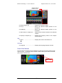
Main Screen Display
(1)
(2)
(3)
(4)
(1) Menu Bar ···························· Contains the Main Menu.
(2) Control Field Window ········· You can perform the same control operations as
with the ThermoController except control of TVS.
For details, see the section called “Utilizing the
ThermoController (TVS Image Transfer Tool).”
(3) Time Scale·························· Indicates the time scale for animation image file
together with the on-scale position of the image
currently being displayed in the Control field
(Point of Display). Clicking on a desired point
of the time scale jumps to that point of time. By
dragging the Point of Display, you can easily
reproduce and view the point.
(4) Edit Animation Area ············ Is used to specify a point of animation image you
desire to edit. This area is not displayed on the
screen while the animation is being reproduced.
Basic Operation
Menu Bar
File
Create new window(W) ············ Opens a new, blank window.
Open... (ctrl+O)························· Opens a dialog box allowing you to specify
and open a thermal animation image file.
Save (ctrl+S)····························· Saves the current file.
53
Advanced Package 1.1 User’s Manual
Nippon Avionics Co., Ltd. 2006
Save As...
Opens a dialog box allowing you to enter a
new name for the current thermal animation
image file and save it as a new file.
Save as still images(I)…··········· Opens a dialog box (shown below) to save the
displayed image in a file. Images can also
be selected from the Pop-up Menu that
appears when you right-click the screen.
Select the type of file to save, file name, and
output destination folder from this dialog box
and click the OK button, and the image will be
saved according to the specified contents.
Save as still images within selected range (R)
Opens a dialog box to save selected multiple
images in a file.
Images can also be
selected from the Pop-up Menu that appears
when you right-click the screen. The dialog
box same as the one for “Save as still images”
shown above will appear.
Save after converting animation image format (E)
Opens a dialog box (shown below) to convert
the present thermal animation image file into
another animation image file.
Specify
Windows Media Video 9 usually.
Other CODECs (compression programs)
have been installed by some applications
other than AdvancedPacakge. Addition of
CODEC permits images to be saved in
various file formats. The compression ratio
and other settings can be changed by
CODEC setting, but continued use of the
initial value is recommended.
54
Advanced Package 1.1 User’s Manual
·· Save
in CSV format (C) …
Nippon Avionics Co., Ltd. 2006
Saves the point temperature trend in a CSV
file.
The CSV file can be opened by
spreadsheet software. When specifying the
range and when pixel skipping is desired, use
the edit function for editing, and then save it in
the CSV format.
Quit ··········································· Closes
the
window
AdvancedPackage.
and
exits
Note that the Save Still Image menu cannot be used when reproduction
of image is not running. Use this menu while reproduction of image is in
pause (when the Reproduce buttons are as shown below).
When the scale unit is specified for the object frame in the still image
saving dialog box, the image will be saved according to the scale shown
in the lower right section of the animation image edit area. When the
frame unit is specified, all the selected frames will be saved as still
images.
Edit
Undo (ctrl+Z)····························· Undoes the last edit action in a field control.
Cut (ctrl+X) ······························ Removes the selected frame in a field control.
Copy (ctrl+C)
Paste (ctrl+V)···························· Pastes copied frames. The screen shown
below will open during execution. Specify
the data pasting position.
Delete (Del) ······························ Deletes the selected frame.
Paste in New Window (W) ······ Open the new window, and paste.
Select All (ctrl+A) ······················ Selects all the frames in a field control.
························· Makes a copy of the selected frame.
55
Advanced Package 1.1 User’s Manual
Nippon Avionics Co., Ltd. 2006
Frame rate change (F) … ········· Reduces the overall number of frames to
downsize the file. This is a function that
makes the animation image file size compact
by reducing the number of these frames.
The number of frames that can be changed
should be a divisor of the current number of
frames.
If the object animation contains both thermal and visual images, the
divisor of the number of thermal image frames must be selected.
View
Thermo ····································· Displays only thermal images.
Visible ······································· Displays only visual images.
Mixing ······································ Mixes the images on display.
Display Scale (S) ······················ Changes over to scale display.
Display Graph (G)····················· Changes over to graph display
Display Point (P)······················· Turns on/ off the display of point.
Set for each point (A) ·············· Opens the submenu for setting by point.
z
Point 1 ················ Turns point 1 on/off.
z
Point 2 ················ Turns point 2 on/off.
z
Point 3 ················ Turns point 3 on/off.
z
Point 4 ················ Turns point 4 on/off.
z
Point 5 ················ Turns point 5 on/off.
Contract time scale (S) ··········· Shortens the time scale.
Expand time scale (L) ············· Lengthens the time scale.
Chapter list (C) ························· Turns ON/OFF the chapter list display.
Search (S)
Find (F) ··································· Opens the search dialog box. Specify the
point temperature condition, and the frame in
question can be searched.
Seach Right (R) ························ Frames are searched rightward (future) from
the present frame according to the condition
specified by Find (F).
Seach Left (L) ··························· Frames are searched leftward (past) from the
present frame according to the condition
specified by Find (F).
56
Advanced Package 1.1 User’s Manual
Nippon Avionics Co., Ltd. 2006
Search dialog
Frame search based on the combination of five conditions of point temperature is
possible. Refer to “Point Condition” on page 36 for the method of setting.
Specify “Select frames that meet search condition,” and the frames that meet the
condition will be selected after search. That range can be saved as a chapter by
using the chapter function.
Play
Play (P)/ Pause (P)
Reproduces or stops reproduction temporarily.
“Temporary Stop” is highlighted during
reproduction run, and “Reproduce” is
highlighted during temporary stop of
reproduction.
Stop (A) ··································· Halts image reproduction run.
Replay only selected range(R) Reproduces image data of the selected area.
Repeat (T)································· Repeats to reproduce image data.
Slow (S) ···································· Slows down
(replaying).
Fast forward (U)························ Speeds
up
(replaying).
Play speed (C) ························ Changes the reproduction run (replaying)
speed.
Previous frame (B)···················· Displays the previous frame.
Next frame (F) ·························· Displays the next frame.
Jump to specified position (G)·· Jumps to the applicable frame according to
the specified frame No. or time.
image
image
reproduction
run
reproduction
run
Chapter (C)
Chapter registration (A) ············ Registers the selected frame as a chapter.
After registration, it will be registered in the
chapter list shown within the red frame in the
figure below.
57
Advanced Package 1.1 User’s Manual
Nippon Avionics Co., Ltd. 2006
Chapter window
ON/OFF button
Delete Chapter (R) ··················· Deletes the selected chapter.
UP (U)······································· Moves the selected chapter position to one
line above.
DOWN (D) …···························· Moves the selected chapter position to one
line below.
Select frame in chapter (S)······· Selects all the frames included in the selected
chapter.
Property of chapter (P) ············· Displays the property screen of the chapter
(shown below).
Help
About… ·········································· Displays the version information box.
Language
Language ······································ Displays the language selection window.
Control Field Window
You can perform the same control operations as with the ThermoController except
control of TVS. For details, see the section called “Utilizing the ThermoController
(TVS Image Transfer Tool).”
Chapter window
ON/OFF button
58
Advanced Package 1.1 User’s Manual
Nippon Avionics Co., Ltd. 2006
Time Scale
This scale indicates the time scale for animation image file together with the
on-scale position of the image currently being displayed in the Control field (Point of
Display). Clicking on a desired point of the time scale jumps to that point of time.
By dragging the Point of Display, you can easily reproduce and view the point.
Point of display
Time scale
59
Advanced Package 1.1 User’s Manual
Nippon Avionics Co., Ltd. 2006
Edit Animation Area
This area is used to specify a point of animation image you desire to edit. This
area is not displayed on the screen while the animation is being reproduced.
(1) Previous frames
(2) Center frame
(3) Thermal
image
(5) Next frames
(4) Visual image
(6) Frame rate
(7) Frame
numbers
(9) Interlocked
(8) Frame time
(10) Scale selection
(1), (5) Previous/Next frames ··· Shifts frames before and behind following the
current time scale on display. Use these
buttons for fine adjustment of frames you need
to edit. You can change the center frame by
continuously holding down these buttons.
(2) Center frame ······················· Displays the frame currently being displayed on
the screen at the center of this area.
(3) Thermal image ···················· Displays the thermal image frame.
(4) Visual image························ Displays the visual image frame.
(6) Frame rate··························· Indicates the frame rates for the respective
images.
(7) Frame numbers ··················· The current series of frame numbers starting
from “zero” (the head frame).
(8) Frame time ·························· The current frame time starting from
“00:00:00.000” (the head frame).
(9) Interlocked··························· Check the “Interlock reproduction” checkbox if
you desire to interlock the frames in this area
with the image in the Control field. This feature
is useful for searching the point to be edited.
Note: Checking this checkbox increases the load
on your PC, which could cause slowdown in
reproduction speed to some types of PC
depending on the specifications; therefore, we
recommend you to deselect (empty) the
checkbox when your aim is to run reproduction
of images.
(10) Scale selection ·················· Selects the unit of the time scale from among
“frame/second/minute/hour.” Copying, deleting,
and all other command operations included in
the Edit Menu are performed based on the
selected unit.
60
Advanced Package 1.1 User’s Manual
Nippon Avionics Co., Ltd. 2006
Scale Display
As mentioned above, copying, deleting, and all other command operations included
in the Edit Menu are performed based on the selected unit. Examples are
illustrated below for your better understanding.
Example) For 30-second frame animation images
With “frame scale”
1 scale
2 scale
3 scale
4 scale
5 scale
(1 frame)
(2 frame)
(3 frame)
(4 frame)
(5 frame)
…
With “second scale”
1 scale
2 scale
3 scale
4 scale
5 scale
(1-30 frame)
(31-60 frame)
(61-90 frame)
(91-120 frame)
(121-150 frame)
…
With “minute scale”
1 scale
2 scale
3 scale
4 scale
5 scale
(1-1800 frame)
(1801-3600 frame)
(3601-5400 frame)
(5401-7200 frame)
(7201-9000 frame)
…
Selecting a Scale (Frame)
Follow the instructions below to select a scale (frame):
Mouse click ······························· When you click the mouse on a scale, that
scale is selected and all scales previously
selected are cancelled.
Shift + Click······························· You can select all the scales from the one on
which you click the mouse to that on which
you click the mouse while holding down the
Shift key.
Ctrl + Click ································ You can reverse the selection state (Selected
- Non-selected) of the scale on which you
click the mouse without canceling the scales
previously selected.
The selection state is held even when the selected scale goes out of the
display screen by operation of the Previous and Next Frame buttons.
Selection depends on the selected unit of the time scale. For example, if you
have previously selected the “second scale” and you select scale 1 for an
animation file photographed at 60 fps, this means that you are selecting the
image of 60 frames.
61
Advanced Package 1.1 User’s Manual
Nippon Avionics Co., Ltd. 2006
Graph Area
Select View (V) → Graph Display (G) on the menu bar, or touch the F7 key to
display the graph. The point temperature trend graph will be displayed.
To return to the scale (animation image editing) display, select View (V) → Scale
Display (S), or touch the F6 key.
①Graph Display ON/OFF
③Graph Area
②Temperature Scale
⑤Present Cursor
④Interlock with Replay
⑦Drawing Density
⑥Time Scale
(1) Graph display ON/OFF ················· Checks the point to display.
(2) Temperature scale························· This temperature range is the vertical axis
of the graph.
(3) Graph area ···································· Graph display area
(4) Interlock with replay ······················ When checked, the graph moves
simultaneously with replay.
(5) Present cursor ······························· Indicates the image shown in the upper
section. It moves right or left when the
light blue cursor (line) or the S mark is
dragged.
(6) Time schedule (horizontal axis)····· Specifies the time of one frame of the
horizontal axis.
(7) Drawing density····························· Specifies the drawing density. If the
drawing density is increased when the file
size is large, drawing will take time.
62
Advanced Package 1.1 User’s Manual
Nippon Avionics Co., Ltd. 2006
Editing Animation Image Data
Deleting Unnecessary Head Frames
1. Select the three head frames, for example.
Frame
0
1
2
3
4
5
6
7
8
・
Source
A
B
C
D
E
F
G
H
I
・
・・
2. Run Delete.
Frame
0
1
2
3
4
5
6
7
8
・
Source
D
E
F
G
H
I
J
K
L
・
・・
Unifying Two Animation Images
1. Start the ThermoMovieEditor twice and read each respective image.
ThermoMovieEditor (Source)
ThermoMovieEditor (Destination)
A
B
Open
Open
2. Using the ThermoMovieEditor for the source image, select all frames and
copy them.
ThermoMovieEditor (Source)
ThermoMovieEditor (Destination)
A
B
Select
Copy
3. Paste the source image to that of destination using the ThermoMovieEditor
for the latter.
ThermoMovieEditor (Source)
A
ThermoMovieEditor (Destination)
B
A
Paste
Note that you cannot copy or paste between the following files:
1. Copy of an animation file containing both thermal and visual image data
to another animation file that contains only thermal or visual image
data.
2. Copy of an animation file containing only thermal image data to another
animation file that contains only visual image data
3. Copy of an animation file containing only visual image data to another
animation file that contains only thermal image data
4. Copy between animation files having different frame rates (except such
animation file containing both thermal and visual image data and whose
thermal image frame rate coincides with that of the thermal image
contained in the file of destination).
63
Advanced Package 1.1 User’s Manual
Nippon Avionics Co., Ltd. 2006
Changing the Frame Rate
This feature is used to make the animation image file size compact by reducing the
number of frames.
From the File Menu, choose Change Frame Quantity. A window opens allowing
you to specify the number of frames. Specify a desired number and click the OK
button. After change is complete, save the new file using the Save or Save As
menu.
The number of frames that can be changed should be a divisor of the current
number of frames.
If the object animation contains both thermal and visual images, the divisor of
the number of thermal image frames must be selected.
Saving Still Image Data
The selected frame can be saved in a thermal image file (.iri).
From the File Menu, choose Save Still Image. A window opens allowing you to
specify the file name. This item can also be selected from the Pop-up Menu that
appears when you right-click the screen.
Note that the Save Still Image menu cannot be used when reproduction
of image is not running. Use this menu while reproduction of image is in
pause (when the Reproduce buttons are as shown below).
64
Advanced Package 1.1 User’s Manual
Nippon Avionics Co., Ltd. 2006
Appendix
Chapter
A
7
Appendix 1
Specifications for Thermal Animation
Image File
File Structure
The thermal animation image file is based on TIFF File Format (Tag Image File
Format), except a part of the format which is the original specifications of our own.
TIFF Header
8byte (fixed length)
12byte x
IFD0
Movie Data Section
Data Section
Structure of Thermal Movie File
65
Advanced Package 1.1 User’s Manual
Nippon Avionics Co., Ltd. 2006
Thermal Animation Image File Layout
DEC
HEX
0x00
0x02
0x04
0x08
NAME
Byte order
Version
Offset to IFD0
IFD0 Tag Counts
10
0x0A
Image Width
(H. Pixel Counts)
22
0x16
Image Length
(V. Pixel Counts)
34
0x22
Maker
46
0x2E
Model Name
58
0x3A
Strip Offsets
(Offset to Movie Data)
70
0x46
StripByteCounts
82
0x52
Thermal Movie File
Version
94
0x5E
Movie File Type
106
0x6A
Record Format
118
0x76
Recording Start Time
130
0x82
Recording Stop Time
0
2
4
8
Tag
Type
Count
Value
Tag
Type
Count
Value
Tag
Type
Count
Value
Tag
Type
Count
Value
Tag
Type
Count
Value
Tag
Type
Count
Value
Tag
Type
Count
Value
Tag
Type
Count
Value
Tag
Type
Count
Value
Tag
Type
Count
Value
Tag
Type
Count
Value
TYPE
ASCII
SHORT
LONG
SHORT
SHORT
SHORT
LONG
LONG
SHORT
SHORT
LONG
LONG
SHORT
SHORT
LONG
LONG
SHORT
SHORT
LONG
LONG
SHORT
SHORT
LONG
LONG
SHORT
SHORT
LONG
LONG
SHORT
SHORT
LONG
LONG
SHORT
SHORT
LONG
LONG
SHORT
SHORT
LONG
LONG
SHORT
SHORT
LONG
LONG
SHORT
SHORT
LONG
LONG
DESCRIPTION
“II”
0x002A
0x00000008
20
256
4 (LONG)
1
320
257
4 (LONG)
1
240
271
2 (ASCII)
16 (Fixed Length)
0x000000FE
272
2(ASCII)
16 (Fixed Length)
0x0000010E
273
4 (LONG)
1
0x00010DE6
279
4 (LONG)
2
0x011E
33024
4 (LONG)
1
0x00000001
33025
4 (LONG)
1
*Reffer to following
33026
4 (LONG)
1
*Reffer to following
33027
2(ASCII)
32 (Fixed Length)
0x00000126
33028
2(ASCII)
32 (Fixed Length)
0x00000146
66
Byte Count
2
2
4
2
2
2
4
4
2
2
4
4
2
2
4
4
2
2
4
4
2
2
4
4
2
2
4
4
2
2
4
4
2
2
4
4
2
2
4
4
2
2
4
4
2
2
4
4
Advanced Package 1.1 User’s Manual
DEC
HEX
NAME
Nippon Avionics Co., Ltd. 2006
142
0x8E
Thermal Movie Rate
[fps]
154
0x9A
Visual Movie Rate
[fps]
166
0x0A6
Number of Editing
Times
178
0x0B2
Cameraman
190
0x0BE
Place of
Thermography
202
0x0CA
Point Information
214
0x0D6
Alarm Condition
226
0x0E2
Comment
Information
238
0x0EE
Chapter Infomation
250
254
270
286
294
326
0x0FA
0x0FE
0x10E
0x11E
0x126
0x146
NEXT IFD
Maker Name
Model Name
StripByteCounts
Recording Start Time
Recording Stop Time
TYPE
Tag
SHORT
Type
SHORT
Count
LONG
Value
LONG
Tag
SHORT
Type
SHORT
Count
LONG
Value
LONG
Tag
SHORT
Type
SHORT
Count
LONG
Value
LONG
Tag
SHORT
Type
SHORT
Count
LONG
Value
LONG
Tag
SHORT
Type
SHORT
Count
LONG
Value
LONG
Tag
SHORT
Type
SHORT
Count
LONG
Value
LONG
Tag
SHORT
Type
SHORT
Count
LONG
Value
LONG
Tag
SHORT
Type
SHORT
Count
LONG
Value
LONG
Tag
SHORT
Type
SHORT
Count
LONG
Value
LONG
LONG
Data
Data
ULONGLONG
Data
Data
DESCRIPTION
33029
4 (LONG)
1
Thermal Movie Rate [fps]
33030
4 (LONG)
1
Visual Movie Rate [fps]
33031
4 (LONG)
1
0x00000000 (Initial Value)
33032
2 (ASCII)
64
0x00000166
33033
2 (ASCII)
64
0x000001A6
33034
1 (BYTE)
1024 (Fixed Length)
0x000001E6
33035
1 (BYTE)
1024 (Fixed Length)
0x000005E6
33036
2 (ASCII)
1024 (Fixed Length)
0x000009E6
33037
1 (BYTE)
65536 (Fixed Length)
0x00000DE6
0x00000000
Avio
TVS-500
Data Size
yyyymmddhhmmssnnn
yyyymmddhhmmssnnn
358
0x166
Cameraman
Data
Cameraman
422
486
1510
2534
3558
69094
0x1A6
0x1E6
0x5E6
0x9E6
0x0DE6
0x10DE6
Data
Data
Data
Data
Data
Data
Place of Thermography
Point Information
Alarm Condition
Comment
Chapter Information
Header of Movie
69158
0x10E26
Place of Thermography
Point Information
Alarm Condition
Comments
Chapter Information
Header of Movie
1st Farme of Movie
Data
:
Nth Frame of Movie
Data
Data
1st Farme of Movie Data
64
:
:
Data
Nth Frame of Movie Data
67
Byte Count
2
2
4
4
2
2
4
4
2
2
4
4
2
2
4
4
2
2
4
4
2
2
4
4
2
2
4
4
2
2
4
4
2
2
4
4
4
16
16
8
32
32
64
1024
1024
1024
65536
64
:
Advanced Package 1.1 User’s Manual
Nippon Avionics Co., Ltd. 2006
List of User Tags
Thermo movie file version
Tag Value
DEC
HEX
33024
0x8100
Movie file type
33025
0x8101
Recording format
33026
0x8102
Recording start time
33027
0x8103
Tag Name
Recording stop time
33028
0x8104
Thermal movie speed (fps)
33029
0x8105
Visual movie speed (fps)
33030
0x8106
Editing times
33031
0x8107
Cameraman
33032
0x8108
Place of thermography
33033
0x8109
Point information
33034
0x810A
Alarm condition
33035
0x810B
Comments
33036
0x810C
Chapter information
33037
0x810D
Animation Image File Type
Value
Type name
DEC
0
1
2
Thermal image only
Visual image only
Both image
HEX
0x00
0x01
0x02
Image Recording Format
Value
Format
DEC
0
1
Normal recording
Alarm recording
HEX
0x00
0x01
Point Information
Point Information consists of one point information header and zero or more point
information data.
Point information header
Point information data
Point information data
:
Point information data
Point information header
Item
Size
Description
Number of Point
4
Number of Point Infomation
(Reserve 1)
4
Reserve
(Reserve 2)
4
Reserve
(Reserve 3)
4
Reserve
68
Advanced Package 1.1 User’s Manual
Nippon Avionics Co., Ltd. 2006
Point information dat
Item
Size
Description
Type
4
A kind of Point
Left position
2
Left position
Top position
2
Top position
Width
2
Width
Height
2
Height
(Reserved)
4
Reserved
Alarm Condition
Alarm Condition consists of one alarm conditional header and zero or more alarm
conditional data.
Alarm condition header
Alarm condition data
Alarm condition data
:
Alarm condition data
Alarm Conditional Header
Item
Size
Description
4
Count of alarm condition
Count of alarm condition
Condition
2
AND / OR
(Reserve 1)
2
Reserve
(Reserve 2)
4
Reserve
(Reserve 3)
4
Reserve
Alarm Conditional Data
Item
Size
Point Nunber
4
Minimum Temperature
4
Maxmum Temperature
4
Minimum Tenperature Type
2
Maxmum Tenperature Type
2
Condition
2
Use/ Not use
2
Description
ポイント No
AND/OR
Chapter Information
Chapter Information consists of one chapter information header and zero or more
chapter information data.
Chapter information header
Chapter information data
Chapter information data
:
Chapter information data
69
Advanced Package 1.1 User’s Manual
Nippon Avionics Co., Ltd. 2006
Chapter Information Header
Item
Count of capter
Size
4
Description
Count of capter data
(Reserve 1)
4
Reserve
(Reserve 2)
4
Reserve
(Reserve 3)
4
Chapter Information Data
Item
Start frame number
Size
8
Description
Start frame number
End frame number
8
End frame number
Name of chapter
64
Name of chapter
memo
128
memo
(Reserve 1)
48
Reserve
Animation Data Division Format
Animation Data Division is composed of one header division and one or more
frames.
Fixed length
Fixed length
Header
Frame No. 1
Fixed length
Frame No. 2
:
Fixed length
Frame No. N
Animation Data Division Structure
Header Division (64 Bytes)
No
1
Offset
0
Item
Size
4
2
4
Movie file type
3
8
Total frame count
8
4
16
Frame size
4
5
20
Thermo image data size
4
154240
6
24
Visual image data size
4
230400
7
28
Thermo Image speed (fps)
2
8
30
2
9
32
10
36
11
40
Visual Image speed (fps)
“lowDateTime” of recording start
FILETIME
“highDateTime” of recording start
FILETIME.
Playback rate (ms)
4
12
44
Reserved
20
Version
Value
0x00000000
4
70
4
4
reserved
Advanced Package 1.1 User’s Manual
Nippon Avionics Co., Ltd. 2006
Frame
Each frame stores one frame captured by an infrared camera.
Thermal and visual images are combined in one frame.
Different frame formats are used when only thermal or visual images are to be
stored in one frame.
The frame size must be a multiple of 4 Kbytes. If the total sum of thermal
and visual images does not coincide with the frame size, there will be a
margin.
Frame header information
Thermal image
Multiple of 4 Kbytes.
Visual image
There will be a margin if the
total sum of images is not a
multiple of 4 KB.
Margin
When recording thermal
and visual images
Frame header information
Frame header information
Thermal image
Visual image
Margin
Margin
When recording visual
image only
When recording thermal
image only
Frame Header (48 Bytes)
No
1
Offset
0
Item
Frame number
サイズ
8
2
8
Thermal image data yes/ no
2
3
10
Visual image data yes/ no
2
4
12
Thermal frame number
4
5
16
Visual frame number
4
6
20
lowDateTime of FILETIME
4
7
24
highDateTime of FILETIME
4
8
28
(Reserve 1)
4
9
32
(Reserve 2)
4
10
36
(Reserve 3)
4
11
40
(Reserve 4)
4
12
44
(Reserve 5)
4
71
Value
Advanced Package 1.1 User’s Manual
Appendix 2
Nippon Avionics Co., Ltd. 2006
CSV File Format
Comma-delimited text data is output in the order shown below. The data up to
linefeed is one record (1 = Frame).
Frame No., recording time (year), (month), (day), (minute), (second), (millisecond),
Point 1 temperature, Point 2 temperature, Point 3 temperature, Point 4 temperature,
Point 5 temperature, and unit of temperature.
Sample of text
Frame No.,Recording Date (Year),Recording Date (Month),Recording Date
(Day),Recording Date (Hour),Recording Date (Minute),Recording Date
(Second),Recording Date (Milli Second),P1,P2,P3,P4,P5,Temperature Unit
1,2006,6,29,19,32,35,896,35.7,,,,,C
2,2006,6,29,19,32,35,928,35.4,,,,,C
3,2006,6,29,19,32,35,960,35.3,,,,,C
4,2006,6,29,19,32,35,992,35.5,,,,,C
5,2006,6,29,19,32,36,24,35.3,,,,,C
6,2006,6,29,19,32,36,56,35.7,,,,,C
7,2006,6,29,19,32,36,88,35.8,,,,,C
8,2006,6,29,19,32,36,120,35.9,,,,,C
9,2006,6,29,19,32,36,152,33.9,,,,,C
10,2006,6,29,19,32,36,184,28.0,,,,,C
11,2006,6,29,19,32,36,216,27.1,,,,,C
12,2006,6,29,19,32,36,248,26.8,,,,,C
Sample of table (Example in which text sample is loaded into a spreadsheet.
Recordi Recordi Recordi Recordi Recordi Recordin Recording
Frame
ng Date ng Date ng Date ng Date ng Date g
Date Date (Milli P1
No.
(Year)
(Month) (Day)
(Hour)
(Minute) (Second) Second)
1
2006
6
29
19
32
35
896
35.7
P2
P3
P4
P5
Tempe
rature
Unit
C
2
2006
6
29
19
32
35
928
35.4
C
3
2006
6
29
19
32
35
960
35.3
C
4
2006
6
29
19
32
35
992
35.5
C
5
2006
6
29
19
32
36
24
35.3
C
6
2006
6
29
19
32
36
56
35.7
C
7
2006
6
29
19
32
36
88
35.8
C
8
2006
6
29
19
32
36
120
35.9
C
9
2006
6
29
19
32
36
152
33.9
C
10
2006
6
29
19
32
36
184
28
C
11
2006
6
29
19
32
36
216
27.1
C
12
2006
6
29
19
32
36
248
26.8
C
72
Please contact your dealer or Nippon Avionics for more information.
Nippon Avionics Co., Ltd.
Overseas Department, Industrial Electronic Products Sales Division
20-1, Nishi-shimbashi 3-chome, Minato-ku, Tokyo 105-0003
TEL: +81-3-5436-0621
FAX: +81-3-5436-0619
7013275-R01A
Rev.1.1
Nippon Avionics Co., Ltd.
CONTACT US
Customer support center, Industrial Electronic Division
Koyato 2-1-1, Samukawa-machi, Koza-gun, Kanagawa-pref.
253-0103 Japan
Tel :
Fax :
E-Mail :
+81-467-73-4426
+81-467-73-4481
[email protected]
Owner’s Record:
Record the date of purchase and your dealer in the space provided below.
Refer to the information whenever you call upon your dealer regarding this product.
Date of Purchase
Dealer’s Name
Telephone
(
)