1
TM
®
SmartSet
Touchscreen Controller Family
Technical Reference Manual
Manual Version 1.0
SmartSet
™
Touchscreen Controller Family
Technical Reference Manual
Manual Version 1.0
Copyright © 1993
by
Elo TouchSystems, Inc.
105 Randolph Road
Oak Ridge, Tennessee 37830
(615) 482-4100
A Raychem Company
All rights reserved.
P/N 008217
DOC # SW000027
Trademark Acknowledgements
IntelliTouch, AccuTouch, and MonitorMouse are registered trademarks, and ELODEV, TouchUp, TouchBack, and
SmartSet are trademarks of Elo TouchSystems, Inc. All other trademarks are the property of their respective holders.
Copyright
Copyright © 1993 by Elo TouchSystems, Inc. All rights reserved. Reproduction, adaptation, or translation without prior
written permission is prohibited, except as allowed under copyright laws. Printed in USA. H??????
Limited Warranty
(a) Elo TouchSystems, Inc., ("Seller") warrants to Buyer that the Products (i) shall be free of defects in materials and
workmanship for three (3) years from the date of shipment for touchscreen components and controllers and one (1) year
from the date of shipment for TouchMonitors (each a "Warranty Period"), (ii) shall conform to Seller's specifications for
such Products throughout the applicable Warranty Period, and (iii) shall be free of liens and encumbrances when shipped
to Buyer. If Seller agrees in writing to provide and does provide system design, drawings, technical advice, or any other
services to Buyer in connection with Products, then Seller further warrants to Buyer during the applicable Warranty Period
that such services shall be undertaken in accordance with Seller's reasonable technical judgment based on Seller's
understanding of pertinent technical data as of the date of performance of such services. Seller's warranties will not apply
to any Product with respect to which there has been (i) improper installation or testing, (ii) failure to provide a suitable
operating environment, (iii) use of the Product for purposes other than that for which it was designed, (iv) failure to
monitor or operate in accordance with applicable Seller specifications and good industry practice, (v) unauthorized
attachment or removal or alteration of any part, (vi) unusual mechanical, physical or electrical stress, (vii) modifications or
repairs done by other than Seller, or (viii) any other abuse, misuse, neglect or accident. In no circumstance shall Seller have
any liability or obligation with respect to expenses, liabilities or losses associated with the installation or removal of any
Product or the installation or removal of any components for inspection, testing or redesign occasioned by any defect or by
repair or replacement of a Product.
(b) Seller makes no warranty regarding the model life of monitors. Seller's suppliers may at any time and from time to time
make changes in the monitors delivered as Products or components.
(c) Buyer shall notify Seller in writing promptly (and in no case later than thirty (30) days after discovery) of the failure of
any Product to conform to the warranty set forth above, shall describe in commercially reasonable detail in such notice the
symptoms associated with such failure, and shall provide to Seller the opportunity to inspect such Products as installed, if
possible. The notice must be received by Seller during the Warranty Period for such Product. Unless otherwise directed in
writing by Seller, within thirty (30) days after submitting such notice, Buyer shall package the allegedly defective Product
in its original shipping carton(s) or a functional equivalent and shall ship it to Seller at Buyer's expense and risk.
(d) Within a reasonable time after receipt of the allegedly defective Product and verification by Seller that the Product fails
to meet the warranty set forth above, Seller shall correct such failure by, at Seller's option, either (i) modifying or repairing
the Product or (ii) replacing the Product. Such modification, repair or replacement and the return shipment of the Product
with minimum insurance to Buyer shall be at Seller's expense. Buyer shall bear the risk of loss or damage in transit, and
may insure the Product. Buyer shall reimburse Seller for transportation costs incurred for Products returned but found by
Seller not to be defective. Modification or repair of Products may, at Seller's option, take place either at Seller's facilities or
at Buyer's premises. If Seller is unable to modify, repair or replace a Product to conform to the warranty set forth above,
then Seller shall, at Seller's option, either refund to Buyer or credit to Buyer's account the purchase price of the Product less
depreciation calculated on a straight-line basis over Seller's stated useful life of the Product (three years for touchscreen
components and controllers and one year for TouchMonitors). THESE REMEDIES SHALL BE BUYER'S EXCLUSIVE
REMEDIES FOR BREACH OF WARRANTY.
(e) EXCEPT FOR THE EXPRESS WARRANTY SET FORTH ABOVE, SELLER GRANTS NO OTHER
WARRANTIES, EXPRESS OR IMPLIED, BY STATUTE OR OTHERWISE, REGARDING THE PRODUCTS, THEIR
FITNESS FOR ANY PURPOSE, THEIR QUALITY, THEIR MERCHANTABILITY, THEIR NONINFRINGEMENT,
OR OTHERWISE. NO EMPLOYEE OF SELLER OR ANY OTHER PARTY IS AUTHORIZED TO MAKE ANY
WARRANTY FOR THE GOODS OTHER THAN THE WARRANTY SET FORTH HEREIN. SELLER'S LIABILITY
UNDER THE WARRANTY SHALL BE LIMITED TO A REFUND OF THE PURCHASE PRICE OF THE PRODUCT.
IN NO EVENT SHALL SELLER BE LIABLE FOR THE COST OF PROCUREMENT OR INSTALLATION OF
SUBSTITUTE GOODS BY BUYER OR FOR ANY SPECIAL, CONSEQUENTIAL, INDIRECT OR INCIDENTAL
DAMAGES.
ii
(f) Buyer assumes the risk and agrees to indemnify Seller against and hold Seller harmless from all liability relating to (i)
assessing the suitability for Buyer's intended use of the Products and of any system design or drawing and (ii) determining
the compliance of Buyer's use of the Products with applicable laws, regulations, codes and standards. Buyer retains and
accepts full responsibility for all warranty and other claims relating to, or arising from, Buyer's Products which include or
incorporate Products or components manufactured or supplied by Seller. Buyer is solely responsible for any and all
representations and warranties regarding the Products made or authorized by Buyer. Buyer will indemnify Seller and hold
Seller harmless from any liability, claims, loss, cost or expenses (including reasonable attorneys' fees) attributable to
Buyer's products or representations or warranties concerning same.
(g) This manual may contain reference to, or information about, Elo products (equipment or programs), that are not now
available. Such references or information must not be construed to mean that Elo intends to provide such products,
programming, or services.
FCC Notice
This device complies with Part 15 of the FCC Rules. Operation is subject to the following two conditions: (1) This device
may not cause harmful interference, and (2) this device must accept any interference received, including interference that
may cause undesired operation.
UL Notice
Elo PC-Bus controllers are for use only with IBM or compatible UL Listed personal computers that have installation
instructions detailing user installation of card cage accessories.
Software License Agreement
BY OPENING THE ACCOMPANYING DISKETTE ENVELOPE, YOU ARE AGREEING TO BECOME BOUND BY
THE TERMS OF THIS AGREEMENT, INCLUDING THIS SOFTWARE LICENSE AND LIMITED WARRANTY.
Software License
This software is protected by both the United States copyright law and international treaty provisions. Therefore, except as
noted below, you should treat the software just like any other copyrighted material. Elo TouchSystems, Inc. (Elo)
authorizes you to make archival copies of the software for the purposes of backing-up your software and protecting your
investment from loss, and to make additional copies for use within a single company or facility.
THIS SOFTWARE IS LICENSED FOR USE ONLY WITH ELO TOUCHSCREENS.
The enclosed software program object code (drivers, utilities, diagnostics, and/or demonstration programs) may be freely
duplicated or distributed without charge, but may not be resold. You may not decompile, reverse assemble, reverse
engineer, or patch any software program object codes.
Any supplied software program source code is proprietary and may not be disclosed to third parties. Such source code may
be modified and/or partially or completely incorporated into your own applications, together with any supplied object code,
and the resulting programs may be used, given away or sold without additional licenses or fees.
You may not reproduce, distribute, or revise the program documentation without expressed written consent from Elo.
This software and accompanying written materials may contain reference to, or information about, Elo products
(equipment or programs), that are not now available. Such references or information must not be construed to mean that
Elo intends to provide such products, programming, or services.
Limited Warranty
THIS SOFTWARE AND ACCOMPANYING WRITTEN MATERIALS ARE PROVIDED "AS IS" WITHOUT
WARRANTY OF ANY KIND. FURTHER, ELO DOES NOT GUARANTEE, OR MAKE ANY REPRESEN-TATIONS
REGARDING THE USE, OR THE RESULTS OF THE USE, OF THE SOFTWARE OR ACCOMPANYING WRITTEN
MATERIALS IN TERMS OF CORRECTNESS, ACCURACY, RELIABILITY OR CURRENTNESS. IF THE
INCLUDED SOFTWARE OR ACCOMPANYING WRITTEN MATERIALS ARE DEFECTIVE, YOU, AND NOT
ELO OR ITS DEALERS, DISTRIBUTORS, AGENTS, OR EMPLOYEES, ASSUME THE COST OF ALL
NECESSARY SERVICING, REPAIR, OR CORRECTION. THE ENTIRE RISK AS TO THE RESULTS AND
iii
PERFORMANCE OF THE SOFTWARE AND ANY FURTHER PROGRAMS OR WRITTEN MATERIALS
DEVELOPED UTILIZING THESE MATERIALS IS ASSUMED BY YOU.
Elo warrants only that the diskette is free from defects in material and workmanship under normal use and service for a
period of sixty (60) days after receipt.
Elo's entire liability and your exclusive remedy as to the diskette shall be, at Elo's option, either return of the purchase price
or replacement of the diskette.
EXCEPT AS PROVIDED ABOVE, ELO DISCLAIMS ALL WARRANTIES, EITHER EXPRESSED OR IMPLIED,
INCLUDING BUT NOT LIMITED TO IMPLIED WARRANTIES OF MERCHANTABILITY AND FITNESS FOR A
PARTICULAR PURPOSE, WITH RESPECT TO THE SOFTWARE, WRITTEN MATERIALS OR DISKETTE. IN NO
EVENT SHALL ELO BE LIABLE FOR ANY INCIDENTAL OR CONSEQUENTIAL DAMAGES OF ANY KIND.
Governing Law
This Agreement shall be governed by and construed in accordance with the laws of the State of Tennessee.
iv
v
Contents
Introduction.................................................................................................. 1
About this Manual ................................................. Error! Bookmark not defined.
Installation.................................................................................................... 7
DOS Demonstration Program .................................................................. 25
Introduction ........................................................... Error! Bookmark not defined.
DOS Touchscreen Driver and Calibration Utility.................................... 35
Introduction ........................................................... Error! Bookmark not defined.
MonitorMouse for DOS ............................................................................. 47
Introduction ........................................................... Error! Bookmark not defined.
MonitorMouse for Windows ..................................................................... 71
Introduction ......................................................................................................... 71
Configuring Your Controller................................................................... 105
General Information .......................................................................................... 105
Troubleshooting ...................................................................................... 117
General Information .............................................. Error! Bookmark not defined.
Error Messages ....................................................................................... 121
ELODEMO Error Messages.............................................................................. 121
vi
vii
1
Introduction
• SmartSet Controllers and Features 1
• Theory of Operation 3
• About this Manual 6
The SmartSet™ controller family is designed for use with Elo TouchSystems
resistive technology touchscreens. SmartSet controllers provide the drive signals
for the touchscreen, convert the received analog signals into digital touch
coordinates, and send them to the host computer. These controllers are the result
of twenty years of experience in resistive controller engineering at Elo.
SMARTSET CONTROLLERS AND FEATURES
The following controllers make up the SmartSet controller family.
E271-2200
E271-2210
E271-2201
E271-2202
Full-featured serial RS-232 controller
Reduced footprint serial RS-232 controller
PC-Bus controller
Micro Channel controller
Features of all SmartSet controllers include:
• Support for all AccuTouch® and DuraTouch® touchscreens. (DuraTouch
touchscreens are no longer manufactured by Elo).
1
2
Chapter 1 - Introduction
• High speed -- can transmit over 200 coordinates per second.
• Bi-directional communication with acknowledgements.
• Sophisticated command set and communication protocol consistent among the
SmartSet controllers.
• On-board calibration and scaling of touch coordinates, untouch detection
(lifting of the finger), and programmable coordinate output rate.
• Configuration options can be stored in nonvolatile RAM (NVRAM) or set with
jumpers.
• Advanced four-layer surface-mount design for small size and low profile.
CMOS circuitry insures low power consumption. Custom ASICs enhance
reliability. Full power and ground planes enhance noise immunity and radio
frequency interference (RFI) immunity. Analog input filters also eliminate
electrical noise from the display. Rugged bipolar transistors are used to drive
the touchscreen and the output stage is protected by Raychem PolySwitches.
Linearity is preserved with a ratiometric measurement subsystem.
• Electrically and 100% functionally tested with a microprocessor-controlled
automated test set.
• On-board diagnostics and LED status indicators.
E271-2200 Serial Controller
• Uses the popular EIA RS-232C serial interface for connection to a wide range
of host computers.
• Communication parameters may be configured for a variety of serial
characteristics and baud rates (up to 38K baud).
• Hardware and software handshaking supported, along with packet checksums
for reliable communications.
• Has a 3.3" x 4.325" outline and low profile.
• Low power requirements: 65ma @ +5Vdc ±10% standby, 160ma average
when touched, 240ma peak. Special low-power mode for battery operation.
• AccuTouch E271-140, DuraTouch E261-280, and IntelliTouch® E281A-4002
controller emulation.
E271-2210 Serial Controller
Same as the E271-2200 with the following exceptions:
Theory of Operation
3
• Smaller footprint: 3.3" x 2.1".
• Maximum baud rate is 19.2K.
• Lower power requirements: 55ma @ +5Vdc ±10% standby, 160ma average
when touched, 240ma peak.
• Lower cost.
E271-2201 PC-Bus Controller
• Half-slot PC-Bus controller (for ISA and EISA systems).
• Host communication can be polled or interrupt-driven.
• I/O address and interrupt (IRQ) selectable through software or jumpers.
• AccuTouch E271-141 and DuraTouch E271-142 controller emulation.
E271-2202 Micro Channel Controller
• Half-slot controller for PS/2 computers with Micro Channel architecture.
• Host communication can be polled or interrupt-driven.
• I/O address and interrupt (IRQ) set via the "automatic configuration"
procedure on the IBM Reference Disk.
THEORY OF OPERATION
Each SmartSet controller has the circuitry needed to interface an Elo resistive
touchscreen to a host computer. Functionally, the circuitry may be divided into the
following categories:
• Drive circuitry which applies electrical signals to the touchscreen.
• A measurement subsystem which detects and digitizes signals returned from
the touchscreen.
• Interface circuitry (serial, PC-Bus, or Micro Channel).
• A microprocessor which directs the operation of the various controller
subsystems.
The following section describes how each of these component subsystems operate
to measure coordinates from an Elo touchscreen.
4
Chapter 1 - Introduction
The AccuTouch Touchscreen
The AccuTouch Model E274 touchscreen consists of a glass panel formed to
match the shape of the underlying display surface. A hard-coated plastic cover
sheet is suspended over the surface of the glass by tiny separator dots. The cover
sheet may be clear for best image clarity or have an anti-glare finish. See Figure 11 for detail on the construction of the AccuTouch touchscreen.
The glass is covered with a uniform resistive coating, and the plastic cover sheet
has a conductive coating. With a light touch on the cover sheet, the conductive
coating on the plastic contacts the resistive coating on the glass. There is an
electrical drive connection to each of the four corners of the resistive coating, and
a pickup connection to the coating on the cover sheet. When the proper DC
voltages are applied to the drive connections, the voltage at the pickup connection
is proportional to the position of the touch.
Figure 1-1. AccuTouch Touchscreen
The logical sequence of operation for the SmartSet controller, used in combination
with the E274 touchscreen, is as follows:
1. When the controller is waiting for a touch, the resistive layer of the
touchscreen (the coating on the glass) is biased at +5V through all four drive
lines, and the cover sheet is grounded through a high resistance. When the
touchscreen is not being touched, the voltage on the cover sheet remains at
zero. The voltage level of the cover sheet is continuously converted by the
analog to digital converter (ADC) and monitored by the microprocessor on the
controller. When the touchscreen is touched, the microprocessor detects the
rise in the voltage of the cover sheet and begins coordinate conversion.
Theory of Operation
5
2. The microprocessor places the X drive voltage on the touchscreen by applying
+5V to Pins H and X and grounding Pins Y and L.
3. An analog voltage proportional to the X (horizontal) position of the touch
appears on the cover sheet at Pin S of the touchscreen connector. This voltage
is then digitized by the ADC and subjected to an averaging algorithm, then
stored for transmission to the host.
The averaging algorithm reduces noise resulting from contact bounce during
the making and breaking of contact with the touchscreen. Successive X
samples are tested to determine that their values differ by no more than a
certain range. If one or more samples fall outside this range, the samples are
discarded and the process is restarted. This is continued until several
successive X samples fall within the range. The average of these values is used
as the X coordinate.
4. Next, the microprocessor places the Y drive voltage on the touchscreen by
applying +5V to Pins H and Y and grounding Pins X and L.
5. An analog voltage proportional to the Y (vertical) position of the touch now
appears on the cover sheet at Pin S of the touchscreen connector. This signal is
converted and processed as described above for the X position.
6. Successive coordinate pairs are sampled to eliminate the effects of noise. If a
sample does not fall within an internal range, all X and Y coordinates are
discarded and the X sequence is restarted at step 2.
7. Once acceptable coordinates have been obtained, an average coordinate is
determined and communicated to the host processor.
Parameters for the internal filtering algorithms can be adjusted through software
setup. See Filter command, page 82.
The X and Y values are similar to Cartesian coordinates, with X increasing from
left to right and Y increasing from bottom to top. These absolute coordinates are
arbitrary and unscaled, and will vary slightly from unit to unit. The SmartSet
controller can be calibrated to align the touchscreen coordinate system with the
display image, reorient each axis, and scale the coordinates before they are
transmitted to the host.
The DuraTouch Touchscreen
SmartSet controllers can operate with four-wire DuraTouch resistive
touchscreens, although these are no longer manufactured by Elo. For a description
of the touchscreen and the theory of operation, see the E261-280 DuraTouch
Serial Touchscreen Controller User's Manual.
6
Chapter 1 - Introduction
ABOUT THIS MANUAL
This manual provides technical information on the Elo SmartSet controller family.
Details are given in this manual on the features, configurations, connections, and
specifications of the SmartSet controllers.
This manual also includes examples of writing a software interface, such as a
device driver, for the controller. Elo supplies such a driver, called ELODEVTM,
for the IBM PC and PS/2 family of computers and compatibles that use the MSDOS operating system. Elo also supplies mouse emulation with its
MonitorMouse® family of drivers for DOS, Microsoft Windows, OS/2, and
Macintosh platforms. Other third-party drivers and interfaces are also available.
Contact Elo for details.
A SmartSet Companion Disk is included with this manual which contains the
sample driver source code and the SmartSet software setup utility, both described
in this manual. See the !READ.ME! file, if present, for any changes or additions to
this manual.
The rest of this manual is organized as follows:
Chapter 2
Explains how to set up the controllers with jumpers.
Chapter 3
Details the controller connections and installation procedures.
Chapter 4
Gives a tutorial on the important operating characteristics of the
SmartSet controller interface using the SmartSet software setup
utility.
Chapter 5
Describes the communication protocol with the controllers and
provides the information you'll need for writing a software
interface. Example C code is included.
Chapter 6
Provides a command reference for the SmartSet controller software
interface.
Appendix A
Details optional data output formats and emulation modes.
Appendix B
Gives algorithms for coordinate scaling.
Appendix C
Lists controller specifications.
For more information on the AccuTouch product line, including touchscreen and
controller options, installation, and troubleshooting, see the AccuTouch Product
Manual.
2
Controller Jumper Settings
• General Information 7
• E271-2200 Serial Controller 10
• E271-2210 Serial Controller 12
• E271-2201 PC-Bus Controller 17
• E271-2202 Micro Channel Controller 22
GENERAL INFORMATION
SmartSet controllers are shipped preconfigured for use with the Elo ELODEV and
MonitorMouse driver software. For most users, no changes are necessary.
Required jumper settings and options available for your controller are listed in the
ELODEV Installation Guide and Programmer's Reference Manual (version 1.5),
MonitorMouse for OS/2 User's Guide (version 2.0), or the MonitorMouse for
Macintosh User's Guide (serial controllers only). If your software does not use Elo
drivers, check your third-party documentation for required jumper settings.
The E271-2200, E271-2210, and E271-2201 controllers can also be jumpered to
emulate other Elo controllers. See the corresponding sections in this chapter for
details.
If you are writing your own driver software, the information in this chapter will
detail all options available through jumpers. The SmartSet controllers can also be
configured through software setup. Jumpers can easily be used to select the
7
8
Chapter 2 - Controller Jumper Settings
power-on configuration, and then software used to adjust parameters at any time.
A DOS software setup utility is included on the SmartSet Companion Disk for this
purpose, or you can write your own code with the information provided in this
manual. Options selected through software can be stored in the controllers'
nonvolatile memory (NVRAM) as power-on defaults.
One jumper (J7) specifies which set of power-on defaults are used. If the jumper is
installed, the controller boots with the settings specified by the jumpers, and
ignores the equivalent NVRAM settings. If the jumper is removed, the controller
boots using the settings in NVRAM and ignores the jumpers. If the communication
settings in NVRAM are ever disturbed or unknown, the NVRAM settings can be
restored by rebooting from the jumper settings, reprogramming the proper settings
in NVRAM, and then removing the jumper.
Software setup is more flexible as only a limited number of options are available
through jumpers. The software setup utility can save all settings to a disk file, then
program other controllers to the identical power-on settings with a single
command.
Selecting Power-On Settings with Jumpers
Jumper blocks may have a horizontal or vertical orientation, as shown in Figure 21. The figure shows jumpers installed normally for J1 and J7. Because some
jumpers work in tandem with others, a cross-connection may also be significant. A
valid cross-connection is shown between J2 and J3. Jumpers with an invalid crossconnection, as with J5 and J6, have no effect and are available as extra jumpers.
Figure 2-1. Jumpering SmartSet Controllers
NOTE
To enable use of the jumpers, J7 must be installed. If J7 is not installed, power-on
settings are from NVRAM.
Selecting Power-On Settings from NVRAM
Jumper J7 must not be installed to enable power-on settings from NVRAM. For
information on the software setup utility SMARTSE**T.EXE, see Chapter 4.
General Information
Proceed to the page shown for your controller:
E271-2200 Serial Controller
E271-2210 Serial Controller
E271-2201 PC-Bus Controller
E271-2202 Micro Channel Controller
page 10
page 12
page 17
page 22
9
10
Chapter 2 - Controller Jumper Settings
E271-2200 SERIAL CONTROLLER
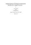
The following figure shows the mounting dimensions, jumper locations,
connections, and pinouts for the E271-2200 controller.
Figure 2-2. E271-2200 Serial Controller
The following lists the jumper settings for the E271-2200 controller. These
settings are identical in function to those of the E271-2210 controller. Proceed to
page 14 for details on each setting.
Power-On Settings
Jumpers
NVRAM
Reserved
Touchscreen Type
AccuTouch
DuraTouch
Mode
Stream
Single-Point
Hardware Handshaking
Enabled
Disabled
Output Format
Binary
ASCII
Baud Rate
(From Top)
J7-Y
J7-N
J6-N
J5-Y
J5-N
J4-N
J4-Y
J3-N
J3-Y
J2-N
J2-Y
E271-2200 Serial Controller
9600
2400
1200
300
19200
Emulation Mode
None
E271-140
E261-280
E281A-4002
Reserved
Reserved
J1-N
J0-N
J1-N
J0-Y
J1-Y
J0-N
J1-Y
J0-Y
Cross connect (connect jumper
vertically so the left pins of J0 and J1
are jumpered)
(From Left)
J11-N
J10-N
J11-N
J10-Y
J11-Y
J10-Y
J11-Y
J10-N
J9-N
J8-N
11
12
Chapter 2 - Controller Jumper Settings
E271-2210 SERIAL CONTROLLER
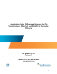
The following figure shows the mounting dimensions, jumper locations,
connections, and pinouts for the E271-2210 controller. Mounting holes marked
with an 'X' are non-plated through-holes (NPTH).
Figure 2-3. E271-2210 Serial Controller
The following table lists the jumper settings for the E271-2210 controller. These
settings are identical in function to those of the E271-2200 controller.
Baud Rate
9600
2400
1200
300
19200
Output Format
Binary
ASCII
Hardware Handshaking
Enabled
Disabled
(From Left)
J0-N
J1-N
J0-Y
J1-N
J0-N
J1-Y
J0-Y
J1-Y
Cross connect (connect jumper
horizontally so the top pins of J0 and J1
are jumpered)
J2-N
J2-Y
J3-N
J3-Y
E271-2210 Serial Controller
Mode
Stream
Single-Point
Reserved
Reserved
Power-On Settings
Jumpers
NVRAM
Reserved
Reserved
Emulation Mode
None
E271-140
E261-280
E281A-4002
J4-N
J4-Y
J5-N
J6-N
J7-Y
J7-N
J8-N
J9-N
J10-N
J11-N
J10-Y
J11-N
J10-Y
J11-Y
J10-N
J11-Y
13
14
Chapter 2 - Controller Jumper Settings
Selecting the Data Transmission Rate
The E271-2200 and E271-2210 communicate with the host computer through a
serial port. Set the data transmission rate of the controller to match that of the
computer's serial port. Jumpers J0 and J1 control the baud rate as follows:
Baud Rate
9600
2400
1200
300
19200
J0
J1
none
none (shipped setting)
installed
none
none
installed
installed
installed
----cross connected----
The defaults for the other communication parameters are 8 data bits, 1 stop bit,
and no parity.
A software command may also be used to select a wider range of data transmission
rates and other communication parameters. All communication parameters can be
saved in NVRAM as a power-on default. See the Parameter command, page 95,
for details.
Selecting the Data Format
The E271-2200 and E271-2210 controller touch coordinate output may be either
ASCII characters or binary data. Jumper J2 controls the format, in combination
with the emulation mode jumpers J10 and J11 (see page 16). For details of the
standard Touch packet, see page 102. For other formats, including emulation
modes, see Appendix A.
If you are using Elo driver software, J2 must not be installed.
Format
Binary
ASCII
J2
not installed (shipped setting)
installed
ASCII format is useful in troubleshooting installations with a dumb terminal or
modem software in local mode. Binary mode is more efficient for communication
with driver programs.
A software command may also be used to select a wider range of data formats.
The data format can be saved in NVRAM as a power-on default. See the Emulate
command, page 80, for details.
E271-2210 Serial Controller
15
Hardware Handshaking
E271-2200 and E271-2210 controllers support hardware handshaking. Jumper J3
is used to enable or disable hardware handshaking. If disabled, the controllers
ignore the DTR and RTS lines.
Hardware Handshaking J3
Enabled
not installed (shipped setting)
Disabled
installed
A software command may also be used to select a wider range of hand-shaking
options. Handshaking options can be saved in NVRAM as a power-on default. See
the Parameter command, page 95, for details.
Choosing Single-Point or Stream Modes
Jumper J4 selects Single-Point or Stream Mode on all SmartSet controllers.
Mode
Stream
Single-Point
J4
not installed (shipped setting)
installed
If Single-Point Mode is selected, a single coordinate pair is communicated for each
touch. No further coordinates are communicated until the finger is lifted (untouch),
and the touchscreen is retouched.
If Stream Mode is selected, the controller sends coordinate pairs continuously until
untouch.
If you are using Elo driver programs, Stream Mode is required.
A software command may also be used to select a wider range of modes. Modes
can be saved in NVRAM as a power-on default. See the Mode command, page 90,
for details.
Selecting the Touchscreen Type
The E271-2200 controller is shipped with jumper J5 installed for E274 AccuTouch
5-wire touchscreens. If you are using a 4-wire DuraTouch touchscreen (no longer
manufactured by Elo), remove the jumper at J5.
Touchscreen Type
AccuTouch
DuraTouch
J5
installed
(shipped setting)
not installed
16
Chapter 2 - Controller Jumper Settings
Emulation Mode
If you are using driver software that does not directly support the SmartSet
protocol, the E271-2200 and E271-2210 controllers can be set up through jumpers
for hardware compatibility with the AccuTouch E271-140 controller, IntelliTouch
E281A-4002 controller (2.0 or later firmware), or the DuraTouch E261-280
controller.
When the controller is in an emulation mode, it will not respond to the SmartSet
protocol. For descriptions of the protocols in the various emulation modes, see
Appendix A.
As an alternative to full emulation modes, a software command may be used to
select a wide range of output data formats. The output data format can be saved in
NVRAM as a power-on default. See the Emulate command, page 80, for details.
To select an emulation mode, set the jumpers as follows:
Emulation Mode
None (SmartSet Mode)
Jumpers
J10-N (shipped setting)
J11-N
AccuTouch E271-140
J10-Y
J11-N
IntelliTouch E281A-4002 J10-N
(2.0 or later firmware)
J11-Y
DuraTouch E261-280
J10-Y
J11-Y
When emulation mode is enabled, J2 selects ASCII or binary emulation in the
protocol specified by J10 and J11.
Reserved Jumpers
Jumpers J6, J8, and J9 on the E271-2200 and E271-2210 controllers are reserved.
They should not be installed.
E271-2201 PC-Bus Controller
17
E271-2201 PC-BUS CONTROLLER
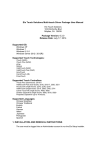
The following figure shows the dimensions, jumper locations, connections, and
pinouts for the E271-2201 controller.
Figure 2-4. E271-2201 PC-Bus Controller
The following lists the jumper settings for the E271-2201 controller.
Power-On Settings
Jumpers
NVRAM
Reserved
Touchscreen Type
AccuTouch
DuraTouch
Mode
Stream
Single-Point
Interrupt
None (Polled)
IRQ2
IRQ3
(From Top)
J7-Y
J7-N
J6-N
J5-Y
J5-N
J4-N
J4-Y
J3-N
J2-N
J3-Y
J2-Y
J3-Y
J2-N
18
Chapter 2 - Controller Jumper Settings
IRQ5
J3-N
J2-Y
Cross-connect (connect jumper
vertically so the left pins of J2 and J3
are jumpered)
IRQ7
Base Port (in hex)
280 (recommended)
240
180
100
2A0
J1-N
J0-N
J1-N
J0-Y
J1-Y
J0-N
J1-Y
J0-Y
Cross connect (connect jumper
vertically so the left pins of J0 and J1
are jumpered)
E271-141 Emulation Mode
(From Top)
Enable
J10-Y
Disable
J10-N
Resolution
(E271-141 Emulation Mode Only)
8-Bit
J11-Y
12-Bit
J11-N
Selecting the Base I/O Port
The E271-2201 uses eight consecutive I/O ports. The Base I/O Port is specified by
jumpers J0 and J1. The values of the settings are as follows:
Base I/O Port (Hex)
280
240
180
100
2a0
J0
J1
none
none (shipped setting)
installed
none
none
installed
installed
installed
----cross connected----
A software command may also be used to select a wider range of Base I/O Ports.
Any base address that is a multiple of 8 can be used. The Base I/O Port can be
saved in NVRAM as a power-on default. See the Parameter command, page 95,
for details.
Choose an I/O address block carefully so it will not contend with another device.
E271-2201 PC-Bus Controller
19
Selecting the Interrupt (IRQ)
The E271-2201 may be operated in either Polled or Interrupt Mode. In Interrupt
Mode, the controller signals the host that data is available. In Polled Mode, the
host software must poll the controller for information.
To use Interrupt Mode, you may install jumpers at J2 and/or J3 to select the
Interrupt (IRQ). For Polled Mode, neither jumper should be installed.
Interrupt
None (polled)
IRQ5
IRQ3
IRQ2
IRQ7
J2
J3
none
none (shipped setting)
installed
none
none
installed
installed
installed
----cross connected----
A software command may also be used to select a wider range of Interrupt values.
Any Interrupt from IRQ2 to IRQ7 can be used. The Interrupt can be saved in
NVRAM as a power-on default. See the Parameter command, page 95, for
details. If you are using Elo driver programs, jumper the controller for Polled
Mode as the IRQ is selected by software setup (unless E271-141 emulation mode
is selected with J10).
Choose the Interrupt carefully so it is not the same as another device.
The following table lists the devices assigned to each interrupt in a PC/XT and a
PC AT:
IRQ
2
3
4
5
6
7
XT
IBM EGA, IBM network
COM2
COM1
Hard disk controller
Floppy disk controller
LPT1
AT/386/486
Mapped to IRQ9
COM2
COM1
LPT2
Floppy disk controller
LPT1
Elo's recommendations for choosing an interrupt, in order of preference, are listed
below. Compare these interrupts with the tables above, skipping the interrupt if a
conflict exists.
XT: 7,3,4,2,6,5
AT/386/486: 5,7,2,3,4,6
To avoid any chance of interrupt contention, you should design the driver software
to disable the interrupt line drivers of contending devices where possible, such as
serial and parallel controllers.
20
Chapter 2 - Controller Jumper Settings
Choosing Single-Point or Stream Modes
Jumper J4 selects Single-Point or Stream Mode on all SmartSet controllers.
Mode
Stream
Single-Point
J4
not installed (shipped setting)
installed
If Single-Point Mode is selected, a single coordinate pair is communicated for each
touch. No further coordinates are communicated until the finger is lifted (untouch),
and the touchscreen is retouched.
If Stream Mode is selected, the controller sends coordinate pairs continuously until
untouch.
If you are using Elo driver programs, Stream Mode is required.
A software command may also be used to select a wider range of modes. Modes
can be saved in NVRAM as a power-on default. See the Mode command, page 90,
for details.
Selecting the Touchscreen Type
The E271-2201 controller is shipped with jumper J5 installed for E274 AccuTouch
5-wire touchscreens. If you are using a 4-wire DuraTouch touchscreen (no longer
manufactured by Elo), remove the jumper at J5.
Touchscreen Type
AccuTouch
DuraTouch
J5
installed
(shipped setting)
not installed
Emulation Mode
If you are using driver software that does not directly support the SmartSet
protocol, the E271-2201 controller can be set up through jumpers for hardware
compatibility with the AccuTouch E271-141 controller (or the DuraTouch E271142 controller).
When the controller is in an emulation mode, it will not respond to the SmartSet
protocol. For descriptions of the protocols in the various emulation modes, see
Appendix A.
To select emulation mode, set the J10 jumper as follows:
Emulation Mode
J10
E271-2201 PC-Bus Controller
None (SmartSet Mode)
E271-141
21
not installed (shipped setting)
installed
8- and 12-Bit Modes
When E271-141 emulation mode is enabled, J11 selects whether 8-Bit or 12-Bit
Mode is emulated.
Mode
8-Bit
12-Bit
J11
installed
not installed
The 12-Bit Mode offers greater resolution. 8-bit coordinates are simply 12-bit
coordinates shifted right four bits. Elo driver software internally shifts 8-bit
coordinates left four bits. This way, new calibration points are not required when
switching between 8- and 12-Bit Modes. Calibration is discussed in Chapter 4.
In 8-Bit Mode, a single two-byte transfer is required to read both the X and Y
coordinates. In Interrupt Mode, a single interrupt must be serviced for each
coordinate pair.
In 12-Bit Mode, two separate two-byte transfers are required to read the X and Y
coordinates. In Polled Mode, each polling results in one two-byte transfer. Two
pollings are required for each coordinate pair, one for X and one for Y. In
Interrupt Mode, two interrupts must be serviced for each coordinate pair.
Reserved Jumpers
Jumper J6 on the E271-2201 controller is reserved. It should not be installed.
22
Chapter 2 - Controller Jumper Settings
E271-2202 MICRO CHANNEL CONTROLLER
The following figure shows the dimensions, jumper locations, connections, and
pinouts for the E271-2202 controller.
Figure 2-5. E271-2202 Micro Channel Controller
The following lists the jumper settings for the E271-2202 controller.
Power-On Settings
Jumpers
NVRAM
Reserved
Touchscreen Type
AccuTouch
DuraTouch
Mode
Stream
Single-Point
Reserved
Reserved
Reserved
Reserved
(From Top)
J7-Y
J7-N
J6-N
J5-Y
J5-N
J4-N
J4-Y
J3-N
J2-N
J1-N
J0-N
E271-2202 Micro Channel Controller
23
Selecting the Base I/O Port
The E271-2202 uses eight consecutive I/O ports. The Base I/O Port is determined
by running the "automatic configuration" on the PS/2 Reference Disk. An Adapter
Description File (.ADF) is included on the ELODEV User's Disk (1.5 or later), the
MonitorMouse for OS/2 disk (2.0 or later), and the SmartSet Companion Disk.
See the installation instructions in the ELODEV or MonitorMouse for OS/2
manuals, or Chapter 3 in this manual for instructions.
Selecting the Interrupt (IRQ)
The E271-2202 may be operated in either Polled or Interrupt Mode. The Interrupt
(IRQ) is determined by running the "automatic configuration" on the PS/2
Reference Disk. An Adapter Description File (.ADF) is included on the ELODEV
User's Disk (1.5 or later), the MonitorMouse for OS/2 disk (2.0 or later), and the
SmartSet Companion Disk. See the installation instructions in the ELODEV or
MonitorMouse for OS/2 manuals, or Chapter 3 in this manual for instructions.
By default, Interrupt Mode is selected. If you wish to use the controller in Polled
Mode, run the "change configuration" on the Reference Disk, and change the IRQ
to "None".
Choosing Single-Point or Stream Modes
Jumper J4 selects Single-Point or Stream Mode on all SmartSet controllers.
Mode
Stream
Single-Point
J4
not installed (shipped setting)
installed
If Single-Point Mode is selected, a single coordinate pair is communicated for each
touch. No further coordinates are communicated until the finger is lifted (untouch),
and the touchscreen is retouched.
If Stream Mode is selected, the controller sends coordinate pairs continuously until
untouch.
If you are using Elo driver programs, Stream Mode is required.
A software command may also be used to select a wider range of modes. Modes
can be saved in NVRAM as a power-on default. See the Mode command, page 90,
for details.
24
Chapter 2 - Controller Jumper Settings
Selecting the Touchscreen Type
The E271-2202 controller is shipped with jumper J5 installed for E274 AccuTouch
5-wire touchscreens. If you are using a 4-wire DuraTouch touchscreen (no longer
manufactured by Elo), remove the jumper at J5.
Touchscreen Type
AccuTouch
DuraTouch
J5
installed
(shipped setting)
not installed
Reserved Jumpers
Jumpers J0, J1, J2, J3, and J6 on the E271-2202 controller are reserved. They
should not be installed.
3
Installation and Connections
• E271-2200 and E271-2210 Serial Controllers 26
• E271-2201 PC-Bus Controller 30
• E271-2202 Micro Channel Controller 32
• Diagnostic LEDs 33
The installation procedure for a SmartSet controller consists of setting the jumpers
on the controller, physically installing the controller, and making connections to
the controller. Use only Elo supplied or approved cabling for best operation and to
insure full regulatory agency compliance.
Read Chapter 2 to determine the jumper settings before installing the controller.
CAUTION
All Elo TouchMonitors have transient protection installed. If you are not using an
Elo TouchMonitor, see the AccuTouch Product Manual for important
information.
25
26
Chapter 3 - Installation and Connections
E271-2200 AND E271-2210 SERIAL CONTROLLERS
Serial Controller Installation
This section assumes you are integrating the E271-2200 or E271-2210 serial
controller board into your system as a component. The controller is also available
in kits and enclosures with cabling and a power supply. See the AccuTouch
Product Manual for various integration options.
The following information gives you the controllers' mounting dimensions, the
touchscreen connections, the power connections and requirements, and the output
connections. It is your responsibility to determine how best to mount the controller
and output connector in the display or separate enclosure, and provide a power
supply.
A Generic Internal AccuTouch Touchscreen Controller Mounting Kit (P/N
UK0020) is available from Elo for mounting the E271-2200 or E271-2210
controller inside a display. It includes wiring harnesses and cables, mounting
hardware, and a DB9 female bulkhead connector. A power supply is available
separately (P/N 400000).
Mounting the Controller and Connecting Chassis Ground
The mounting dimensions for the E271-2200 and E271-2210 controllers shown in
Figure 2-2 and Figure 2-3, pages 10 and 12 respectively. Remember that the cable
headers will increase the space required.
The mounting holes fit common 0.156 inch plastic snap-in standoffs. A chassis
ground connection is required through one of the plated mounting holes (PTH) to
provide a return path for the on-board transient protection. Conductive mounting
hardware can provide a chassis ground connection for the controller.
Serial Controller Connections
Power Connections
The E271-2200 and E271-2210 controllers operate on a single voltage, positive
with respect to ground. See page 121 for power requirements.
Connect a power cable harness to P4 on the controller, a 1x2 header with pins on
0.100" centers. The recommended mating plug is a Molex polarized, locking crimp
terminal housing #22-01-3027. The power connection is labeled to designate the
positive (+) and ground (-) pins. Connect a power supply (such as Elo P/N
400000) to the harness and then to AC.
E271-2200 and E271-2210 Serial Controllers
27
You may provide a suitable power supply and cabling, or Elo can provide them.
See the AccuTouch Product Manual for details.
CAUTION
Observe polarity when connecting the power leads to the power supply. Reversing
polarity may damage the controller.
Serial Connections
The E271-2200 and E271-2210 controllers operate at standard RS232C levels.
The serial port connection is at P2 on the controller, a 2x5 header with pins on
0.100" centers. It is configured so a ribbon cable and commonly available
insulation displacement connectors (IDCs) may be used.
The controller only requires a 2-wire connection, Transmit Data (TXD) and Signal
Ground (GND). Transmit Data should be connected to your computer's Receive
Data (RXD) pin. For two-way communications, the controller's Receive Data pin
should also be connected to the host's Transmit Data pin.
Data Set Ready (DSR) and Clear to Send (CTS) may be used by the host to verify
controller connections and operation. DSR is asserted when power is applied to
the controller and CTS is asserted when the controller's power-on sequence is
complete. Data Terminal Ready (DTR) and Request to Send (RTS) can also be
connected for full hardware handshaking.
Elo's ELODEV driver requires two-way communication (unless the p flag is
used), and all four handshaking lines.
P2 Pins
1
2
3
4
5
6
7
8
9
10
Signal
DCD
DSR
RXD
RTS
TXD
CTS
DTR
RI (N/C)
GND
Key
DB25
8
6
3
4
2
5
20
22
7
DB9
1
6
2
7
3
8
4
9
5
28
Chapter 3 - Installation and Connections
9 7 5 3 1
ÚÄÄÄÄÄÄÄÄÄÄÄÄÄÄÄ¿
³· · · · ·³
³ · · · ·³
ÀÄÄÄÄÄÄÄÄÄÄÄÄÄÄÄÙ
10 8 6 4 2
Figure 3-1. P2 Connector Pin Positions, End View
If you are installing the controller inside a display, for the convenience and safety
of the user, we recommend making a cable which connects P2 to a DB9 female
connector (male connectors are used with external controllers) mounted on the
back of the display. The shell of this connector should be tied to chassis ground.
Use an additional cable from the back of the display to your serial port.
Elo can provide suitable adapters and cabling. See the AccuTouch Product Manual
for details.
Touchscreen Connections
AccuTouch
A five conductor ribbon cable is attached to the AccuTouch touchscreen. The
female connector on the cable mates with the controller's 1x5 touchscreen
connection at P3 (see Figure 3-2). If you are installing the controller outside the
display cabinet, you may need to make up a short cable with a connector that
mates with the touchscreen connector, and a connector on the other end to suit the
installation. Depending on the type of installation, you may or may not need to
install transient protection as described below.
Transient protection is required in all installations where it is possible to turn the
display on or off while the touchscreen is disconnected from the controller.
1. If Elo installed the touchscreen, and the controller is external, a cable with
transient protection is already installed, terminated with a DB9 male connector
mounted on the back of the display. You will need a cable from the DB9
connector to the controller. DB9 pin connections for Elo installed touchscreen
cables are:
1-S, 6-X, 7-Y, 8-L, 9-H
2. If you are installing the touchscreen, and the controller will be located inside
the display cabinet, you will need to make a data cable, but no touchscreen
cable is required.
3. If you are installing the touchscreen, and the controller will be outside the
display cabinet, you must make a touchscreen cable with transient protection.
E271-2200 and E271-2210 Serial Controllers
29
For more information on transient protection, see the AccuTouch Product Manual.
H X S Y L
ÚÄÄÄÄÄÄÄÄÄÄÄÄÄÄÄ¿
³· · · · ·³
ÀÄÄÄÄÄÄÄÄÄÄÄÄÄÄÄÙ
1 2 3 4 5
Figure 3-2. P3 Connector Pin Positions, End View
DuraTouch (E271-2200 Only)
A four conductor ribbon extension cable is usually attached to the DuraTouch
touchscreen. The female connector on the end mates with the controller's 1x4
touchscreen connection at P6. See the section above for information on the
controller placement and transient protection issues.
XH XL YL YH
ÚÄÄÄÄÄÄÄÄÄÄÄÄ¿
³· · · ·³
ÀÄÄÄÄÄÄÄÄÄÄÄÄÙ
1 2 3 4
Figure 3-3. P6 Connector Pin Positions, End View
30
Chapter 3 - Installation and Connections
E271-2201 PC-BUS CONTROLLER
E271-2201 Installation
Follow these steps to install the E271-2201 controller:
1. Discharge any static charge on your body by touching the back of the
computer cabinet.
2. Note the Base I/O Port and Interrupt for use with your driver software. The
factory default settings are 280 (hex) and no Interrupt (Polled Mode). Eight
consecutive I/O ports are used by the E271-2201. Ports 280-287 are typically
not used by other devices. Elo driver software sets the Interrupt through
software setup.
3. Turn the computer off and unplug the AC power cord from the outlet.
4. Remove the computer's cover. Refer to the computer user's manual for this
step.
5. Choose an available expansion slot. On a PC/XT, do not use slot 8. On an AT,
any slot may be used.
6. Remove the retaining screw for the expansion slot's access bracket, then
remove the bracket.
7. Insert the controller into the expansion slot. The controller should seat fully
and the access bracket should mate with the frame of the computer.
8. Replace the retaining screw, insuring that the controller remains seated in the
socket.
9. Replace the computer's cover.
10. If you have a TouchMonitor, plug the DB9 female end of the supplied
touchscreen cable into the DB9 male connector labeled "Touchscreen
Interface" on the back of the TouchMonitor case. Attach the opposite end of
the cable, DB9 male, to the DB9 female connector on the controller. Do not
confuse the touchscreen and video connections.
If you do not have a TouchMonitor, see E271-2201 Connections on the
following page.
11. Plug the AC power cord back in and reboot the computer.
E271-2201 PC-Bus Controller
31
E271-2201 Connections
AccuTouch
The AccuTouch touchscreen typically has a 30 inch cable terminated with a 1x5
female connector. This is normally converted to a DB9 male bulkhead connector
with an adapter cable internal to the display (P/N 012131-K1, included with the
touchscreen kit (P/N E274-XXX-K1). This adapter has built-in transient
protection, and must be connected through a short lead to frame ground. For more
information on transient protection, see Touchscreen Connections, page 28, and
the AccuTouch Product Manual.
An additional external cable (P/N 012143), included with the controller if ordered
as a kit (P/N 002201-K1 or P/N 002202-K1), connects the bulkhead connector to
the DB9 female connector on the controller. See the AccuTouch Product Manual
for cabling kits and options.
The following pinouts apply:
AccuTouch Signal
H
X
S
Y
L
Touchscreen Cable Pin
1
2
3
4
5
Controller DB9 Pin
9
6
1
7
8
DuraTouch
The DuraTouch touchscreen typically has a short flexible cable with a 1x4 female
connector. This must be converted to a DB9 male connector for connection with
the DB9 female connector on the controller.
The following pinouts apply:
DuraTouch Signal
XH
XL
YL
YH
Touchscreen Cable Pin
1
2
3
4
Controller DB9 Pin
6
7
8
9
32
Chapter 3 - Installation and Connections
E271-2202 MICRO CHANNEL CONTROLLER
E271-2202 Installation
1. Copy the file @6253.ADF from the ELODEV User's Disk, the MonitorMouse
for OS/2 (version 2.0 or later) distribution disk, or the SmartSet Companion
Disk to your Backup Copy of your "IBM PS/2 Reference Disk". If you do not
have a backup of your Reference Disk, boot with the Reference Disk in drive
A and follow the on screen instructions to create one.
2. Follow the "Installing an Adapter" instructions in your IBM Personal System/2
Quick Reference. The controller (adapter) may be installed in any available
slot.
3. If you have a TouchMonitor, plug the DB9 female end of the supplied
touchscreen cable into the DB9 male connector labeled "Touchscreen
Interface" on the back of the TouchMonitor case. Attach the opposite end of
the cable, DB9 male, to the DB9 female connector on the controller. Do not
confuse the touchscreen and video connections.
If you do not have a TouchMonitor, see E271-2201 Connections, page 31, for
the E271-2202 touchscreen connector pinouts. (The E271-2202 uses the same
connections as the E271-2201.)
4. Power on with your backup copy of the Reference Disk in drive A. Error 165
-- Adapter Configuration Error -- will appear because you just installed a new
adapter. Press [Enter] on the logo screen, then follow the on screen
instructions to "Automatically configure the system."
5. Next, follow the on screen instructions to "View Configuration" and verify that
the E271-2202 controller was detected. You should see installed in a slot the
"Elo TouchSystems E271-2202 Touchscreen Controller". The Base I/O Port
and selected Interrupt (IRQ) will also be shown. Later, if you have problems or
require a different setup, you can "Change Configuration" of the controller's
Base I/O Port and Interrupt.
6. Quit the program, remove the Reference Disk, and restart the computer. The
system should now boot without any error messages.
E271-2202 Connections
See E271-2201 Connections, page 31.
Diagnostic LEDs
33
DIAGNOSTIC LEDS
E271-2200, E271-2201, and E271-2202 Controllers
The E271-2200, E271-2201, and E271-2202 controllers have three diagnostic
LEDs. Following power on, the controllers perform their self-test. (ELODEV
displays the result of this test when loaded). After the self-test, a flashing green
LED indicates normal operation (except in Low Power Mode, see page 89). If a
fatal error was encountered, the yellow and red LED's flash an eight-bit error code
starting with the most significant bit, where yellow indicates a binary '0' and red a
binary '1'.
During normal operation, the yellow LED indicates controller/host communication
is in progress. For example, when the touchscreen is touched, the yellow LED
should light or flicker (may not be visible with bus controllers on fast PC's). If the
host does not remove the packet from the controller, the LED will stay lit.
If the yellow LED lights without a touch, the touchscreen or cabling may be
shorted. Disconnect the touchscreen cable from the controller and cycle power to
the controller to verify this condition.
A constant red LED indicates a warning error condition, such as improper
communication from the host. Suspect the baud rate or other communication
parameters.
E271-2210 Controller
The E271-2210 controller has one yellow diagnostic LED. Following power on,
the controller performs its self-test. (ELODEV displays the result of this test when
loaded). After the self-test, the LED flashes about 1.5 times a second, indicating
normal operation.
During normal operation, the LED also indicates controller/host communication is
in progress. For example, when the touchscreen is touched, the LED should light
or flicker, then return to the normal flash rate. If the host does not remove the
packet from the controller, the LED will stay lit.
If the LED stays lit without a touch, the touchscreen or cabling may be shorted.
Disconnect the touchscreen cable from the controller and cycle power to the
controller to verify this condition.
If the LED flashes about four times a second, a warning error condition is
indicated, such as improper communication from the host. Suspect the baud rate or
other communication parameters.
4
SmartSet Tutorial
• Introduction to the SMARTSET Program 35
• Running SMARTSET 36
• Sample SMARTSET Session 39
This chapter will introduce some of the important concepts in touchscreen driver
programming as they relate to the SmartSet controllers. The concepts will be
presented in tutorial form using software accompanying this manual.
INTRODUCTION TO THE SMARTSET PROGRAM
The SmartSet Companion Disk includes the program SMARTSET.EXE. The
SMARTSET program, (indicated in this manual by capital letters), requires an
IBM PC or compatible running MS-DOS. We recommend connecting the
SmartSet controller to a PC for this tutorial even if your target platform is not a
PC running DOS. The ELODEV driver is not required.
This tutorial will use the SMARTSET program to go beyond the basic issue of
receiving touchscreen coordinates and demonstrate many of the features of the
SmartSet controller family. These features include on-board calibration, coordinate
scaling, diagnostics, various operating modes, communication protocols, timers,
filtering parameters, and NVRAM. Two-way communication is used between the
host driver software and the controller's firmware for sending commands and
receiving responses.
35
36
Chapter 4 - SmartSet Tutorial
SMARTSET is useful to driver writers in the following ways:
• SMARTSET can be used to experiment with the functionality of each
command in menu form, display the context-sensitive help, and learn how each
option works in conjunction with others, all before writing any driver code.
• Once the controller's features are understood, SMARTSET can be used to
examine the underlying command set and communication. SMARTSET can be
used to send and receive packets of data to the controller in binary or ASCII
form. This protocol must be understood before attempting to write driver
code.
• SMARTSET can be used to test the state of a controller. For example, a
programmer can use SMARTSET to verify a driver changed an option
correctly. In fact, most programmers will choose to program controller options
directly from their driver, rather than using SMARTSET.
Besides programmers, others may use SMARTSET in the following ways:
• SMARTSET can be used to customize the controller, saving all details in a file.
Later, the configuration can be loaded from disk directly into the NVRAM of
other controllers. SMARTSET is not required for use with Elo or third-party
driver software. However, special options such as filtering and timing values
can be adjusted with SMARTSET for use with these drivers.
• SMARTSET can be used for diagnostic purposes.
RUNNING SMARTSET
SMARTSET is invoked by typing:
SMARTSET
at the DOS prompt.
Elo TouchSystems SmartSet(tm) Series Setup Utility Ver. 1.2
Select Interface Type
Serial
PC-Bus
Use -¯ to move cursor bar, [Enter] to select.
Figure 4-1. SmartSet Utility Interface Selection
Select Serial, PC-Bus, or Micro Channel interface. (A selection for Micro Channel
replaces PC-Bus if you are running on a system with a Micro Channel bus.)
Enter the Base I/O Port address or COM port as requested. SMARTSET locates
the controller and displays the controller's jumper settings as shown below:
Running SMARTSET
37
Elo TouchSystems SmartSet(tm) Series Setup Utility Ver. 1.2
Select Interface Type
Serial
PC-Bus
Enter Base I/O Port address in hex ([Enter] accepts): 280
Current Jumper Settings
Screen type:
AccuTouch
I/O:
PC-Bus
Setup is by:
Jumpers
Mode:
Stream
Interrupt #:
None
Base address:
280
Press any key to continue.
Idle
Figure 4-2. SmartSet Utility Jumper Settings Display
NOTE
A warning message is displayed if the controller is not detected. You may proceed
to the Main Menu and SMARTSET will assume default settings for all controller
parameters. You may then change any parameters and save all settings to a disk
file. This file can later be transferred to a connected controller. If you change the
communication parameters from the Main Menu, SMARTSET will attempt to
establish communication with the controller again.
Press a key to display the Main Menu, shown below.
Elo TouchSystems SmartSet(tm) Series Setup Utility Ver. 1.2
Type: 2201/PC-Bus/AccuTouch
ROM Revision: 1.2
Owner ID: EloInc.
ÉÍÍÍÍÍÍÍÍÍÍÍÍÍÍÍÍÍÍÍÍÍÍÍÍÍÍÍÍÍÍÍÍÍÍÍÍÍÍÍÑÍÍÍÍÍÍÍÍÍÍÍÍÍÍÍÍÍÍÍÍÍÍÍÍÍÍÍÍÍÍÍÍÍÍÍÍÍÍ»
º
Main Menu
³
Load/Save Setup
º
ÇÄÄÄÄÄÄÄÄÄÄÄÄÄÄÄÄÄÄÄÄÄÄÄÄÄÄÄÄÄÄÄÄÄÄÄÄÄÄÄÅÄÄÄÄÄÄÄÄÄÄÄÄÄÄÄÄÄÄÄÄÄÄÄÄÄÄÄÄÄÄÄÄÄÄÄÄÄÄ
º L) Load/Save Setup
³ Data Direction:
Save
º
º
³ Data Source/Destination: To Disk
º
º C) Communications
³
º
º M) Touch Mode
³ Setup
º
º P) Touch Reporting
³ 2nd Calib/Scaling
º
º B) Calibration
³
º
º S) Scaling
³ Program Controller
º
º I) Timer
³
º
º F) Filter
³
º
º T) Touch Testing
³
º
º D) Diagnostics
³
º
º R) Reset Controller
³
º
º A) ASCII Setup
³
º
º
³
º
º X) Exit
³
º
ÈÍÍÍÍÍÍÍÍÍÍÍÍÍÍÍÍÍÍÍÍÍÍÍÍÍÍÍÍÍÍÍÍÍÍÍÍÍÍÍÏÍÍÍÍÍÍÍÍÍÍÍÍÍÍÍÍÍÍÍÍÍÍÍÍÍÍÍÍÍÍÍÍÍÍÍÍÍͼ
Communication status:
Communicating with controller.
Help-[F1]:
Use -¯® to move cursor bar, [Enter] to select/modify.
Smartset is:
Idle
Figure 4-3. SmartSet Utility Main Menu
The top of the screen shows the version of the SMARTSET program, the type of
controller and touchscreen, the ROM revision level of the controller firmware, and
the Owner ID string, factory set to "EloInc." unless you have a special OEM
configuration.
The bottom of the screen contains some status information which is updated after
each command. The Communication Status indicates if SMARTSET is
38
Chapter 4 - SmartSet Tutorial
communicating with a connected controller. The communication status may
change if communication parameters are changed. The bottom line says "Idle" if
SMARTSET is ready to accept a command, or indicates a command is in progress.
The help line gives context sensitive help on the highlighted command. Additional
information can be displayed for the highlighted command at any time by pressing
the [F1] key.
The left half of the screen, the Main Menu, lists categories of available controller
commands. The right half, or submenu, lists available controller commands for
each category and their current setting. Use the ??? arrow keys to move the
highlighting up or down on the Main Menu. The submenu changes with each
category. Press the right arrow key or [Enter] to move the highlighting to the
submenu for the highlighted category. Press the left arrow to move back. When the
highlighting is in the submenu, controller parameters may be changed. Hot keys
indicated for the Main Menu categories may be used to jump quickly from
submenu to submenu.
Take a moment to move through the menus using the arrow keys and hot keys.
Press [F1] for help on any category or controller command. Do not change any
settings yet.
Main Menu Categories
The Main Menu includes the following categories, described in general below. All
commands will be detailed later in this manual.
Load/Save Setup
Lets you load and save controller settings to disk and/or
nonvolatile RAM (NVRAM). Saving settings to NVRAM
will change the controller's power-on defaults, unless the
controller is booting from jumper settings. Saving settings
to disk will allow other controllers to be quickly
programmed to the identical settings. Multiple controllers
can be programmed identically by loading settings from
disk, then saving those settings in NVRAM.
Communications
Lets you examine and change the parameters for
communication with the SmartSet controllers. The
parameters and their use vary depending on the interface.
Touch Mode
Various options can be selected for which portions of a
touch will be reported. You may select the initial touch
point, the last point touched (the untouch point), the entire
stream of intervening points (stream points), intervening
points which do not repeat the coordinate value (tracking
Sample SMARTSET Session
39
points), or combinations of these. Touch coordinates may
be trimmed and scaled to specified ranges.
Touch Reporting
Used to select various touch reporting options, touch
packet emulation, and low power mode.
Calibration
A touchscreen calibration sequence may be performed, or
calibration points specified manually. X and Y axes may be
swapped.
Scaling
Touch coordinate scaling ranges can be specified with any
axis inversion.
Timer
Lets you select and configure the on-board timer features of
the controller.
Filter
Allows you to select low-level filtering parameters for
optimizing
controller
performance
for
extreme
environments.
Touch Testing
Allows you to test the touchscreen and see the data
transmitted by the controller.
Diagnostics
Runs the various on-board diagnostic routines.
Reset Controller
Performs a soft or hard reset on the controller.
ASCII Setup
Lets you communicate directly with the controller by
entering command packets with the keyboard. By manually
communicating with the controller and studying its
responses, you can learn the details of the host-controller
interaction.
Exit
Exits the SMARTSET program.
SAMPLE SMARTSET SESSION
We will now proceed to configure some basic operating parameters of the
SmartSet controller. The SMARTSET program will be used to change settings
and examine their effects. Press [F1] for on-line information for each command, or
refer to Chapter 6 for detailed information.
40
Chapter 4 - SmartSet Tutorial
Enabling Touch Reporting
First confirm touch reporting is enabled by pressing "P" for the "Touch Reporting"
menu, then moving the highlighting to "Touch Reporting" and press [Enter] so
"Report" is indicated. (Only serial controllers power-on enabled).
Skip to Touch Testing by pressing "T". Touch the touchscreen. X and Y
coordinates will be displayed for the position of your touch, as well as a constant
Z-axis value, transmitted for compatibility with Elo IntelliTouch touchscreens,
which sense pressure as well as location.
X
1271
1268
1266
1267
1282
1282
901
904
900
912
752
748
760
760
Y
1861
1862
1859
1857
1856
1854
2206
2207
2204
2211
2418
2423
2406
2406
Z
255
255
255
255
255
255
255
255
255
255
255
255
255
255
Press [Esc] to get back to Main Menu
Touch packet format: SmartSet Binary
Status: Touch Flag:
1
Initial
2
Stream
2
Stream
2
Stream
2
Stream
4
UnTouch
1
Initial
2
Stream
2
Stream
4
UnTouch
1
Initial
2
Stream
2
Stream
4
UnTouch
Figure 4-4. SmartSet Utility Touch Testing Display
The Touch Flag indicates whether a touch coordinate is for the point of Initial
touch, the point of release (Untouch), or points between those events (Stream).
Changing the Touch Mode
The SmartSet controller can be configured so it reports any combination of these
types of events. Press [ESC] to exit the Touch Testing screen, and "M" to enter
the Touch Mode submenu. Use the arrow keys and [Enter] to enable various
combinations of "Initial Touches", "Stream Touches", and "Untouches". Type "T"
to return to the Touch Testing screen to examine their effects.
Return the controller to the "Enabled" setting for "Initial Touches", "Stream
Touches", and "Untouches".
Calibration
The need for calibration is unique to the touchscreen. Unlike mouse or keyboard
applications where the cursor is part of the image, a touchscreen is a physical
overlay with an independent coordinate system. Only by knowing the position of
the image can the touchscreen coordinates be converted into image coordinates.
Sample SMARTSET Session
41
Besides the differences in touchscreens and controllers, calibration also
compensates for the variation in video image among displays. The image is
affected by horizontal and vertical adjustments on the monitor and by the physical
mounting of the touchscreen.
Additional calibration complications include image blooming, where bright-colored
images expand, and the "pin cushion" effect, which causes the corners of the
display to be stretched. Poor display linearity can cause similarly-sized boxes to be
larger at the edges of the screen than they are in the middle, or vice-versa. The
displayed image can also be tilted. Even changing video modes can affect the
screen size.
Perfect calibration cannot be achieved in all circumstances. For example, the user
can encounter parallax problems with a change in position, or because the present
user is not the same stature as the person who calibrated the screen.
Even the most sophisticated calibration techniques can only partially overcome
such variations. Therefore, most touchscreen software uses only a two or threepoint calibration sequence and instead relies on well-placed touch zones and
appropriate user feedback.
The three-point calibration sequence used by the SMARTSET program
automatically corrects inverted touchscreen installations and backwards cable
connections.
Type "T" and locate the corner where the X and Y values of the touchscreen are
lowest. This is the default origin of the touchscreen coordinate system. The X and
Y coordinates increase as you move to the diagonally opposite corner. Because the
coordinate values at the extremes of the touchscreen vary with every touchscreen
and controller combination, touchscreen coordinates are only useful if mapped to
the coordinate system of the image behind the touchscreen.
For example, your touchscreen may have its origin in the lower-left corner and
have a coordinate system ranging from 352,536 to 3715,3550. The active area of
the touchscreen will usually extend beyond the image, into the overscan area of
video displays. Your image may have its origin in the upper-left corner and have a
coordinate system from 1,1 to 80,25.
In Figure 4-5, Rx and Ry denote the raw coordinate system of the touchscreen
controller, and Sx and Sy denote the coordinate system for the screen image.
Rxlow, Rylow, Rxhigh, and Ryhigh are the calibration points for the position of
the image in raw coordinates. Given point Cx and Cy in raw coordinates, the X
and Y values must be determined in screen coordinates.
42
Chapter 4 - SmartSet Tutorial
Figure 4-5.Calibration Point Coordinates
We will now use the on-board calibration and scaling features of the SmartSet
controller so coordinates will be reported in the coordinate system of your image.
(If you do not wish to use this feature of the SmartSet controller, Appendix B
gives generalized calibration and scaling algorithms that a driver program can use.)
Go to the Calibration submenu. Note the default calibration points are 0-4095 for
each axis. Choose "Do Calibration", type "C" to calibrate in 80x25 text mode, and
touch the three points indicated.
When you complete the calibration sequence and return to the menu, the
calibration points have been changed. The new calibration points are the
coordinates of the upper-left and lower-right corners of the 80x25 image.
If the default orientation of your touchscreen had the origin in the lower-left
corner, as is typical, the calibration points will reflect a change in orientation by
having a low value greater than the high value in the Y axis. If your origin was in
the upper-right, the X values will be reversed. The process of calibration not only
defines the position of your image, it also aligns the origin of the touchscreen
coordinate system with that of the image. This is called hardware axis inversion.
In general, the first calibration point becomes the origin.
The third calibration point was used only to detect swapped axes. This can correct
inverted cabling or touchscreens rotated 90°. Normally after calibrating, the X/Y
Axis field indicates Normal, not Swapped.
You may have noticed that the calibration routine did not acquire its calibration
points in the corners of the video image. The points taken are offset from the
corners, then extrapolated to achieve an estimated value at the corners. This is
because the image on some monitors is not very linear, and usually least linear in
the corners, due to the "pin cushion" effect. By acquiring calibration points near
the corners instead of at the corners, more of the video will be closely calibrated
with the touchscreen.
Sample SMARTSET Session
43
The calibration routine used by SMARTSET lets you select a video mode
supported by your display before you calibrate. As the screen size and position
may vary among video modes, you should calibrate in the video mode used by
your application. For our example, we calibrated in text mode.
Typically, touchscreen driver developers will write their own calibration routine
rather than using this feature of SMARTSET. Later in this manual, sample source
code for a calibration program is given.
Now Enable the Calibration Mode on the Touch Mode submenu. The calibration
points are ignored until Calibration Mode is enabled.
Return to the Touch Testing screen. Notice that the origin is now in the upper-left
corner, and the coordinate is approximately 0,0 at the edge of the image, and
4095,4095 at the lower right corner of the image. If you touch beyond the image in
the overscan area, you will see negative coordinates in the upper left, and
coordinates greater than 4095,4095 in the lower right.
Range Checking Mode
Next, Enable Range Checking on the Touch Mode submenu. This mode instructs
the controller to check if a touch is within the calibrated area or in the overscan
area.
Return to the Touch Testing screen again. Now the controller indicates "out of
range" by adding 40 to the Status field when you touch the overscan area. Range
Checking does not affect the coordinates. The only effect is a slight degradation in
coordinate throughput because the controller has to perform additional analysis.
Trim Mode
Enable Trim Mode on the Touch Mode submenu. This mode instructs the
controller to push the coordinates of a touch in the overscan area to the edge of
the calibrated area. In most applications, a touch in the overscan area should be
accepted as a valid touch in the closest touch zone on the edge of the image. Trim
Mode only works if Range Checking is also Enabled.
Return to the Touch Testing screen again. The Status still indicates "out of Range"
when you touch the overscan area. However, the coordinates are trimmed to 0,0
and 4095,4095 at the extremes.
Scaling
The process of scaling is similar to that of calibration. Usually it is desired to map
the touch coordinates into a range other than the controller's default range of 0 to
44
Chapter 4 - SmartSet Tutorial
4095. For our example, we will want coordinates scaled to values of 1 to 80
horizontally and 1 to 25 vertically.
Select the Scaling submenu by pressing "S". Change the X Low value to 1, the X
High to 80, the Y Low to 1, and the Y High to 25.
Now return to the Touch Mode submenu and enable Scaling. The scaling values
are ignored until Scaling Mode is enabled.
On the Touch Testing screen, observe how the coordinates are scaled to 80x25.
The combination of calibration and scaling now make the touch coordinates match
the image coordinates. A touch on the touchscreen now reports the character
location on the image. This is the mode where the touchscreen data is most useful
to an application.
Axis Inversion
The coordinate scaling values can be signed numbers from -32767 to +32768. If
the low scale value is greater than the high value, software axis inversion is
indicated. Software axis inversion is performed after any automatic hardware axis
inversions directed by the calibration points. For example, the corrected hardware
origin may be the upper left, but on one application screen, 1st Quadrant
1000x1000 Cartesian Coordinates may be desired with the origin in the lower left.
Simply set the scaling values 0-999 and 999-0 for X and Y. The calibration points
do not need to be changed.
Each axis may also be inverted by selecting the Orientation command on the
Scaling submenu.
Saving the Setup
Once all controller parameters have been configured with the SMARTSET
program, the Load/Save Setup command may be used to load and save the settings
to disk and/or nonvolatile RAM (NVRAM).
Saving settings to NVRAM will change the controller's power-on defaults, unless
the controller is booting from jumper settings (J7 is installed).
Saving settings to disk will allow other controllers to be quickly programmed to
the identical settings.
Type "L" to jump to the Load/Save Setup submenu. Select Save for the Data
Direction, and To Disk for the Destination. Move the highlighting to Setup and
press [Enter]. The status line says it is creating or updating the "SmartSet
configuration file".
Sample SMARTSET Session
45
Before we demonstrate restoring the settings from disk, let's change the settings by
using the Reset command to restore all defaults. Press "R" to jump to the Reset
Menu. Use [F1] to display the differences between Soft Reset and Hard Reset.
Execute a Hard Reset. Depending on OEM options, a Hard Reset may take a few
seconds. Watch the status line until it reports Idle. Scroll through the menus and
verify that the calibration, scaling, modes, and all other parameters are reset.
Now select Load From Disk on the Load/Save Setup submenu. Move the
highlighting to Setup, and press [Enter]. Scroll through the menus and verify that
the calibration, scaling, modes, and all other parameters are restored.
The same procedure is used for loading and saving all parameters from/to
NVRAM. Simply change the Data Source/Destination to NVRAM.
2nd Calibration/Scaling
The SmartSet controllers can also store a secondary set of calibration and scaling
values in NVRAM which can be recalled at any time.
Create a secondary set of calibration and scaling values by changing the values on
the Calibration and Scaling submenus. Now select Save to Disk, highlight 2nd
Calib/Scaling, and press [Enter]. The modified calibration and scaling values are
added to the SMARTSET.DAT file.
Restoring the Setup from Disk will restore the primary calibration and scaling
values. Selecting Load From Disk and 2nd Calib/Scaling will replace the primary
values with the secondary values saved on disk.
The same procedure is used for loading and saving the secondary values from/to
NVRAM. Simply change the Data Source/Destination to NVRAM.
Programming Multiple Controllers
In most applications, more than one touchscreen will be used. The SMARTSET
program includes a feature for quickly configuring power-on defaults on multiple
controllers.
Once a setup has been saved to disk (and optionally secondary calibration and
scaling values), the Program Controller command on the Load/Save Setup
submenu can be used. In one operation, this command loads the setup from disk
and saves it to the controller's NVRAM. The controller can then be replaced with
another controller, and identical settings programmed in one operation.
46
Chapter 4 - SmartSet Tutorial
WHERE TO GO FROM HERE
From the Main Menu, type "R" and select Soft Reset to restore the default settings
of the controller. You may now exit the SMARTSET program by selecting Exit
from the Main Menu.
In the next chapter, we will discuss how data is communicated to the SmartSet
controllers. The ASCII Setup portion of the SMARTSET program will be used to
study this communication and the command structure.
Chapter 6 then describes the commands supported by the SmartSet controllers.
The commands in the SMARTSET program correspond to the controller
command set.
5
Software Interface
• Packet Structure 47
• Interface Specifics 51
• Sample Driver Code 57
This chapter describes the communication between the host computer and the
SmartSet controllers. The basic packet structure is introduced and how packets are
sent and received. The SMARTSET utility is used as a demonstration. Specifics
about each interface are given next, followed by a sample driver in machineindependent C source code.
PACKET STRUCTURE
High-level communication with all SmartSet controllers is through an eight-byte
packet. Packets sent to the controller are called command packets. Packets
received from the controller are called response packets. The command and
response packets are identical for all SmartSet controllers.
For PC-Bus and Micro Channel controllers, packets are transmitted and received
through eight consecutive read/write I/O ports. For serial controllers, the eightbyte packet is transmitted over the serial line framed by two additional bytes for
synchronization. Specifics on the bus and serial interfaces will be covered later in
this chapter.
47
48
Chapter 5 - Software Interface
Commands and Responses
The first byte of each packet is the command byte, and the seven remaining bytes
are the data bytes. The command byte is an ASCII character, currently from 'A' to
'T'. Chapter 6, the Command Reference, details each command and response.
A command byte in upper-case indicates a set command to the controller. The data
bytes then alter an internal setting of the controller.
A command byte in lower-case indicates a query command to the controller. The
data bytes in the query command are ignored by the controller. A query command
tells the controller to report the internal settings of the controller as they relate to
the command. The controller reports this data in a response packet.
The format of the response packet is identical to that of the set command,
including the command byte being in upper-case. This allows the host to query a
current setting, modify a specific parameter, and return the same packet to the
controller as a set command. Unused or unknown parameters can be ignored.
The structure for each type of packet is shown below:
0 1 2 3 4 5 6 7
ÚÄÄÄÂÄÄÄÂÄÄÄÂÄÄÄÂÄÄÄÂÄÄÄÂÄÄÄÂÄÄÄ¿
Query: ³'x'³ 0 ³ 0 ³ 0 ³ 0 ³ 0 ³ 0 ³ 0 ³
ÀÄÄÄÁÄÄÄÁÄÄÄÁÄÄÄÁÄÄÄÁÄÄÄÁÄÄÄÁÄÄÄÙ
0 1 2 3 4 5 6 7
ÚÄÄÄÂÄÄÄÂÄÄÄÂÄÄÄÂÄÄÄÂÄÄÄÂÄÄÄÂÄÄÄ¿
Response:
³'X'³ 1 ³ 2 ³ 3 ³ 4 ³ 5 ³ 6 ³ 7 ³
ÀÄÄÄÁÄÄÄÁÄÄÄÁÄÄÄÁÄÄÄÁÄÄÄÁÄÄÄÁÄÄÄÙ
0 1 2 3 4 5 6 7
ÚÄÄÄÂÄÄÄÂÄÄÄÂÄÄÄÂÄÄÄÂÄÄÄÂÄÄÄÂÄÄÄ¿
Set:
³'X'³ 1 ³ 2 ³ 3 ³ 4 ³ 5 ³ 6 ³ 7 ³
ÀÄÄÄÁÄÄÄÁÄÄÄÁÄÄÄÁÄÄÄÁÄÄÄÁÄÄÄÁÄÄÄÙ
Note the command byte (byte 0) is in lower-case for the query command, and is in
upper-case in the response packet and set commands.
Packet Structure
49
Commands and Acknowledgements
Each command sent to a SmartSet controller is confirmed by an Acknowledge
response. This response packet indicates any errors in the command and any other
pending errors. See page 82 in the Command Reference for a list of the possible
error codes.
A typical query/response/set interaction flows as follows:
Host sends query command packet
Controller sends a response packet
Controller sends an acknowledge response packet
Host sends a set command packet
Controller sends an acknowledge response packet
The only commands that does not return an Acknowledge response are the Hard
Reset and Quiet-all commands.
Let's use the SMARTSET utility to demonstrate this interaction. Type:
SMARTSET
at the DOS prompt, select your interface, and proceed to the Main Menu. (For
more information on using SMARTSET, see Chapter 4.)
Make sure touches are enabled by typing "P". (PC-Bus and Micro Channel
controllers are not enabled by default). Change Touch Reporting to Report as
necessary.
Next select the Touch Mode submenu by typing "M". Initial Touches, Stream
Touches, and Untouches should all be Enabled.
Now type "A" for ASCII Setup. Touch the touchscreen and notice the stream of
packets received by SMARTSET. A sample display is shown in Figure 5-1, page
50.
The "T" in byte 0 indicates the packets are Touch packets. Refer to page 102 for
detailed information on the contents of the Touch packet. Byte 1 contains the
Status bits, the X coordinate is the Intel (byte swapped) integer formed by bytes 2
& 3, Y is in bytes 4 & 5, and Z follows in bytes 6 & 7. As you move your finger,
bytes 2-5 should change. Byte 1 should indicate your Initial Touch, Stream
Touches, and Untouch with 1, 2, and 4 respectively. These values correspond to
the bit positions defined for the Touch packet on page 102. Bytes 6 & 7 are
constant because the current SmartSet controllers do not support a Z-axis.
50
Chapter 5 - Software Interface
B0
54
54
54
54
54
54
54
54
54
54
54
B1
01
02
02
02
02
02
02
02
02
02
04
B2
01
00
02
03
04
06
05
01
01
01
FC
Press [ESC] to get back to Main Menu.
1) Enter any ASCII character from the keyboard. (except '$')
2) Enter a '$' and two hex digits. eg. $01, $0a, $ff
B3 B4 B5 B6 B7: Byte positions
Touch packet format: SmartSet Binary
0C F4 02 FF 00
T.......
0C E4 02 FF 00
T.......
0C E4 02 FF 00
T.......
0C E4 02 FF 00
T.......
0C E4 02 FF 00
T.......
0C E6 02 FF 00
T.......
0C E5 02 FF 00
T.......
0C E3 02 FF 00
T.......
0C E7 02 FF 00
T.......
0C E4 02 FF 00
T.......
0B FA 02 FF 00
T.......
Figure 5-1. SmartSet Utility ASCII Setup Display with Touch Packets
Next, let's send a command to the controller. Type "m" and press [Enter].
Commands in lower-case indicate a query. The Mode command is described on
page 90. Pressing [Enter] causes SMARTSET to fill any unentered bytes will nulls,
and transmit the complete packet to the controller.
B0
54
54
54
54
54
54
54
54
54
54
54
6D
4D
41
B1
01
02
02
02
02
02
02
02
02
02
04
B2
01
00
02
03
04
06
05
01
01
01
FC
00 87
30 30
Press [ESC] to get back to Main Menu.
1) Enter any ASCII character from the keyboard. (except '$')
2) Enter a '$' and two hex digits. eg. $01, $0a, $ff
B3 B4 B5 B6 B7: Byte positions
Touch packet format: SmartSet Binary
0C F4 02 FF 00
T.......
0C E4 02 FF 00
T.......
0C E4 02 FF 00
T.......
0C E4 02 FF 00
T.......
0C E4 02 FF 00
T.......
0C E6 02 FF 00
T.......
0C E5 02 FF 00
T.......
0C E3 02 FF 00
T.......
0C E7 02 FF 00
T.......
0C E4 02 FF 00
T.......
0B FA 02 FF 00
T.......
m.......
00 00 00 00 00
M.......
30 30 00 00 00
A0000...
Figure 5-2. SmartSet Utility ASCII Setup Showing Mode Query
Notice that the Mode query returned a Mode response followed by an
Acknowledge response. Byte 2 of the Mode response is 87 (hex), indicating the
Initial Touch, Stream, and Untouch bits are set, corresponding to what we
observed on the Touch Mode submenu. The reserved Z-axis Disable bit is also set
(not displayed on the Touch Mode submenu).
Let's change the controller into Single-Point Mode by clearing the Initial Touch
and Stream bits in the Mode packet. Type "M", "$00", "$81", [Enter]. Note the
command byte is in upper-case because this is a set command. The '$' keystroke
signals SMARTSET that you are entering a binary value in hex, rather than an
ASCII value. Note the controller returns an Acknowledge response after the set
command. If the "A" is followed by anything but '0's, refer to page 82 for a list of
possible error codes. Retry the Mode set command as necessary.
Now touch the touchscreen again to verify you selected Single-Point Mode. Press
[ESC] and return to the Main Menu. Examine the Mode settings and you will see
Interface Specifics
51
that SMARTSET reflects the changes you made manually in ASCII Setup. When
writing a driver, the SMARTSET utility is valuable for understanding the
query/response/set interaction for the various commands and for verifying the
settings you program into the controller.
You may wish to experiment with other queries in ASCII Setup. Type "o" to query
the Owner string. Type "g" to download the whole configuration of the controller.
You should be able to identify each packet and their contents by referring to
Chapter 6.
From the Main Menu, type "R" and select Soft Reset to restore the default settings
of the controller. Exit SMARTSET.
In the next section, we will detail the communication at an even lower level the
specifics for each type of interface: serial, PC-Bus, and Micro Channel. The
SMARTSET utility hides these details, just as you may hide them at a certain level
when developing a driver that supports multiple interfaces.
INTERFACE SPECIFICS
Serial Controllers
The serial interface uses the eight-byte packet with an additional Lead-in byte and
a trailing Checksum byte for a total of ten bytes.
<Lead in byte><8-byte Command or Response><Checksum byte>
An optional Key byte may also be included. See page 52 for more information.
Lead-in Byte
The Lead-in byte is used to signal the start of a packet. The standard Lead-in byte
is an ASCII 'U' (55h). This character was chosen due to its distinctive alternating
bit pattern.
The Lead-in byte is different if the optional Key byte is included in the packet. See
Key Byte, page 52, for more information.
Checksum Byte
The trailing Checksum byte may be used to validate the serial communication and
to synchronize with the received data stream.
The Checksum is calculated as follows:
52
Chapter 5 - Software Interface
Checksum byte = <AAh> + <Lead in byte> + <8 Data bytes>
where the addition is performed with 8-bit unsigned numbers and overflow is
ignored.
By default, the host is not required to send a properly calculated Checksum in
command packets. A dummy value, such as 0, is required to provide the correct
packet length.
If a higher confidence is needed in the serial communications, the host may use the
Parameter command, (see page 95), to enable Checksum verification by the
controller. With this function enabled, the controller checks each command packet
for a valid Checksum value before processing the command.
Key Byte
An optional format extends the standard serial packet by adding a Key byte. This
extended packet is used in specialized installations where more than one serial
controller is to be connected on a single serial communication link. In such an
installation, a unique Key value may be programmed into each controller with the
Key command, (see page 88), and stored in NVRAM.
A command intended for only one of the interconnected controllers is sent in an
extended packet. Although all controllers on the link receive the command, only
the one with the matching Key processes the command. If a standard packet is sent
along the link, all the interconnected controllers will process the command (it acts
as a global command).
Similarly, responses from each controller contain the programmed Key byte. This
permits the host to discriminate between touch data generated by the controllers.
As there is no standard way of allowing the controllers in this type of installation
to send data on the same serial data line, a custom wired OR configuration is
necessary for the hardware to function properly. The controllers must also have
automatic touch reporting disabled with the Mode command and be polled with a
Touch query issued to each controller. See Touch command, page 102. Other
hardware considerations must also be evaluated when attempting this type of
installation.
The structure of the extended serial communications packet is:
<Lead In byte><8
byte><Checksum byte>
byte
Command
or
Response><Key
Interface Specifics
53
The Lead In byte of an extended packet is an ASCII Control-V character (16h).
The host can check for either a 'U' or ^V as the Lead-in byte. If the byte is a 'U',
the host knows 9 bytes will follow. If the byte is a ^V, 10 bytes will follow.
As with the standard packet, the Checksum is calculated by summing the bytes
without regard to overflow. The Key byte is included in the sum.
Checksum byte = <AAh> + <Lead in byte> + <8 Data bytes> +
<Key byte>
The Key byte is not used by factory default.
Software Handshaking
The controller recognizes the software flow control convention of XON/ XOFF
(ASCII "Control Q" and "Control S"). If the host sends a ^S character to the
controller, outside the context of a command packet, the controller will stop
sending data to the host. Upon receipt of a ^Q, the controller will once again be
enabled to send data to the host.
The controller can also send XOFF/XON characters to the host as a software
handshaking method. Upon receipt of a valid command, a ^S character may be
sent to the host. When the command is processed completely, a corresponding ^Q
is sent. This will allow devices which do not properly handle hardware
handshaking signals to use software flow control.
Software handshaking may be enabled or disabled with the Parameter command
(see page 95). It is disabled by factory default.
Hardware Handshaking
The controller supports hardware handshake signals typically implemented in EIA
RS-232 communications. If the handshaking signals are not connected, the
controller defaults to a transmit-enabled mode.
If the handshaking signals are connected, the following protocol should be used:
The signal DSR (Data Set Ready) is kept asserted by the controller. This signal
indicates to the host that a controller is present and powered on.
The signal DTR (Data Terminal Ready) tells the controller that the host is present.
The controller will only transmit if DTR is asserted by the host. Typically, the host
should keep DTR asserted.
When the controller receives a valid command, it de-asserts the handshaking signal
CTS (Clear To Send). The host should suppress further output until the controller
54
Chapter 5 - Software Interface
has processed the command and is ready to receive another, indicated by when it
asserts CTS.
The host should assert RTS (Request To Send) when it is ready to accept data,
and de-assert RTS when it cannot accept data. Typically, the host will de-assert
RTS while it is processing a complete packet, then reassert RTS when it is ready
to receive another packet.
To ease troubleshooting of the initial installation, jumper J3 can be used to force
the controller to ignore hardware handshaking.
Hardware handshaking may also be enabled, disabled, or inverted with the
Parameter command (see page 95). It is enabled by factory default.
Duplex
When full-duplex is selected, each character sent to the controller is echoed. When
half-duplex is selected, the controller does not retransmit each received character.
Full-duplex mode is useful when a dumb terminal, also in full-duplex mode, is used
to manually test or set up the controller. Half-duplex mode is used if the terminal is
also in half-duplex mode.
Half-duplex mode is normally used when software is communicating directly with
the controller.
Full or half-duplex is selected with the Parameter command (see page 95). Halfduplex is the factory default.
Interface Specifics
55
Bus Controllers
The PC-Bus and Micro Channel SmartSet controllers use read/write I/O ports for
communicating the eight-byte packet.
Base I/O Port
The Base I/O Port is the location of first I/O port through which the controller and
the host exchange data. The Base I/O Port is selected from jumpers or NVRAM
with the E271-2201 PC-Bus controller, and through "automatic configuration"
with the E271-2202 Micro Channel controller. For more information on Base I/O
Port selection, see Chapter 2.
A block of eight consecutive ports are used for the eight-byte packet. They are
denoted as "Base Port", "Base Port + 1", etc., through "Base Port + 7".
To receive a packet from the controller, the host reads the eight I/O ports in
ascending order starting with the Base Port. The controller senses the completion
of the transfer when all eight ports have been read.
To send a packet to the controller, the host writes to the same eight I/O ports in
ascending order starting with the Base Port. The controller processes the
command after all eight ports have been written. A command received by the
controller takes priority over any background processing. This includes the
processing of another command. Therefore, the host must wait for an
Acknowledge response before issuing another command.
The controller informs the host that data is available by clearing a status bit and
optionally asserting an interrupt request line (IRQ). This allows the host driver
software to be polled or interrupt-driven.
Polled Mode
Polled Mode is commonly used in computer systems which do not have a
hardware interrupt signal available to assign to the touchscreen controller. Polled
drivers are easier to write but do not allow multi-tasking or event-driven
programming. (Elo drivers are interrupt-driven).
Bit 7 of the Base Port (the command byte), is the Not Ready bit. If the host is
polling the controller, it should wait until the Not Ready bit is 0 before reading the
remaining bytes. This negative logic is used so bit 7 does not need to be cleared in
response packets before they are resent to the controller as set commands. It also
makes packets received from bus controllers identical to those received from serial
controllers.
56
Chapter 5 - Software Interface
Interrupt Mode
If Interrupt Mode is enabled either by jumpers or software setup, the controller
asserts the selected IRQ signal when data becomes available (as it clears the Not
Ready bit). It is not necessary for the host to poll the Not Ready bit in Interrupt
Mode. Upon interrupt, the host jumps to a corresponding interrupt service routine
(ISR) whose location is stored in its interrupt vector table. The ISR retrieves the
data from the controller and then returns to the interrupted process. A full
discussion on writing interrupt-driven code is language and operating system
dependent, and is beyond the scope of this manual. It is possible to setup the
controller through polling, then switch to interrupt-driven code to receive Touch
packets.
PC-Bus Interrupt Specifics
An IRQ signal can be used by only one device at a time in the PC architecture. It is
possible, however, for the E271-2201 PC-Bus controller to share an IRQ signal
with another device if the other device can release (tri-state) its interrupt line
drivers. Most serial and parallel controllers on the PC have this feature (see the
IBM Technical Reference Manuals).
To share an IRQ, the E271-2201 controller should be programmed to use the IRQ
only when the other device is tri stated. When the other device needs the IRQ, the
host must reprogram the E271-2201 to IRQ0 (Polled Mode). This way, only one
device is driving the interrupt line at a time.
The E271-2201 is shipped without an IRQ jumpered. For information on selecting
an interrupt, see Chapter 2. For the most flexibility, an interrupt-driven driver
should use the Parameter command (see page 95) to select an interrupt as the
driver is loaded.
Micro Channel Interrupt Specifics
Unlike the PC-Bus architecture, an IRQ signal can be shared by more than one
device in the Micro Channel architecture, although the rules for interrupt chaining
are not standardized under DOS. The E271-2202 Micro Channel controller is
capable of sharing an interrupt. (ELODEV does not support interrupt sharing
however).
The Not Ready bit, (bit 7 of the Base Port), can be used by an interrupt-driven
driver program to see if the E271-2202 generated the interrupt. Otherwise, the
driver can jump to the next interrupt service routine in the chain.
The E271-2202 controller is shipped without an IRQ selected. The IBM-supplied
Reference Disk will select a Base I/O Port and IRQ after examining the .ADF files
Sample Driver Code
57
for the E271-2202 controller and other adapters. See E271-2202 Installation,
page 32, for more information.
SAMPLE DRIVER CODE
The rest of this chapter provides sample application and driver code for SmartSet
touchscreen controllers. The example code is written in ANSI C and organized in
modules as follows:
Figure 5-3. Example Code Organization
EXAMPLE1.C and EXAMPLE2.C are sample applications. Each uses high-level
interface-independent controller interface functions in PACKET.C, such as
querycommand() and setcommand(). The interface-dependent functions are
supplied in SERIAL.C for the E271-2200 or E271-2210 serial controllers, or
BUS.C for the E271-2201 PC-Bus controller and the E271-2202 Micro Channel
controller.
BUS.C contains some code that is Micro Channel specific. This code is
commented for easily deletion if support on this architecture is not required.
SERIAL.C is written to be machine-independent. The PC-dependent serial port
configuration and character input/output code is given in PC_COMM.C.
PC_MISC.C contains miscellaneous PC-dependent code to clear the screen, hide
the cursor, etc. PC_COMM and PC_MISC can be rewritten for other
architectures. Source code for all modules is included in this chapter, except for
PC_COMM.C and PC_MISC.C. All source code can be found on the Companion
Disk.
58
Chapter 5 - Software Interface
Example1 - Display Controller Defaults and Raw Touch Coordinates
EXAMPLE1.C polls Elo SmartSet touchscreen controllers. The controller ID,
jumper settings, and power on diagnostics results are displayed, as shown in Figure
5-4 on the following page. Raw touch coordinates are then displayed, along with
the status flag, indicating initial touch, stream touches, and untouch.
C:\>example1
ID:
Controller revision level: EloInc. 1.2
Z axis: Not available
Jumper settings:
Touchscreen type: AccuTouch
Interface: PC-Bus
Boot from: Jumpers
Mode: Stream
Interrupt: 0
Base address: 280
Touch screen for polled [X Y Z Status] output.
Press any key to abort...
1203 2846
255
1
1376 2691
255
2
1651 2457
255
2
1903 2272
255
2
2280 1980
255
2
2515 1773
255
4
Figure 5-4. EXAMPLE1.C Output
In the following source code, initcontroller(), defined in SERIAL.C or BUS.C,
detects and initializes the controller. An error condition aborts the program with a
message describing the problem. The querycommand(), checkdiags(), and
gettouch() functions are defined in PACKET.C. Source code for these modules is
included later in this chapter. Refer to the Command Reference in Chapter 6 for
the structure of the owner, id, jumpers, and diag packets used in displayjumpers().
/*************************************************************************
EXAMPLE1.C
Polls Elo SmartSet touchscreen controllers.
Displays controller ID, jumper settings, and raw touch coordinates.
**************************************************************************/
#include <stdio.h>
#include <conio.h>
#include <stdlib.h>
#include <string.h>
#include <ctype.h>
#include "packet.c"
/* SmartSet interface independent code */
#include "pc_misc.c"
/* miscellaneous PC dependent code */
void displayjumpers(void);
/*************************************************************************/
int main(void)
{
int x,y,z,flags;
initcontroller();
checkdiags();
displayjumpers();
printf("\nTouch screen for polled [X Y Z Status] output.\n");
printf("Press any key to abort...\n");
do {
if (gettouch(&x,&y,&z,&flags))
printf("%6d%6d%6d%6X\n",x,y,z,flags);
} while (!kbhit());
while (kbhit())
/* flush keystroke */
getch();
disablecontroller();
Sample Driver Code
return(0);
}
void displayjumpers(void)
{
int i;
packettype id,owner,jumpers;
printf("ID:\n");
id[0] = 'i'; querycommand(id);
owner[0] = 'o'; querycommand(owner);
printf(" Controller revision level: ");
for (i=1; i<8; i++)
printf("%c",owner[i]);
printf(" %d.%d\n",id[5],id[4]);
printf(" Z axis: ");
if (id[3] & 0x80)
printf("Available\n");
else
printf("Not available\n");
printf("Jumper settings:\n");
jumpers[0] = 'j'; querycommand(jumpers);
printf(" Touchscreen type: ");
switch(jumpers[1]) {
case '0': printf("AccuTouch\n"); break;
case '1': printf("DuraTouch\n"); break;
case '2': printf("IntelliTouch\n");
}
printf(" Interface: ");
switch(jumpers[2]) {
case '0': printf("Serial\n"); break;
case '1': printf("PC-Bus\n"); break;
case '2': printf("Micro Channel\n");
}
printf(" Boot from: ");
if (jumpers[3] == '0') printf("Jumpers\n");
else printf("NVRAM\n");
printf(" Mode: ");
if (jumpers[4] == '0') printf("Single Point\n");
else printf("Stream\n");
if (jumpers[2] == '0') {
/* serial controller */
printf(" Hardware handshaking: ");
if (jumpers[6] == '1') printf("Enabled\n");
else printf("Disabled\n");
printf(" Output format: ");
if (jumpers[7] == '0') printf("ASCII\n");
else printf("Binary\n");
}
else {
printf(" Interrupt: %d\n", jumpers[5]);
printf(" Base address: %X\n", jumpers[6]+(jumpers[7] << 8));
}
}
#include "bus.c"
/* for E271-2201 and E271-2202 */
/* #include "serial.c" */
/* for E271-2200 and E271-2210 */
59
60
Chapter 5 - Software Interface
Example2 - Calibrate and Finger Paint
EXAMPLE2.C also polls Elo SmartSet touchscreen controllers. The controller is
first set up for calibration by changing the Mode to report raw coordinates. The
calibration screen appears as follows:
XXXXXXXXXXXXXXXXXXXXXXXXXXXXXXXXXXXXXXXXXXXXXXXXXXXXXXXXXXXXXXXXXXXXXXXXXXXXXXXX
X
X
X
X
X
*
X
X
X
X
X
X
X
X
X
X
X
X
X
X
X
X
Touch the following points from a
X
X
position of normal use, e.g. a sitting
X
X
person of average height and reach.
X
X
You will hear a beep after each touch.
X
X
X
X
X
X
X
X
X
X
X
X
X
X
X
X
X
X
X
XXXXXXXXXXXXXXXXXXXXXXXXXXXXXXXXXXXXXXXXXXXXXXXXXXXXXXXXXXXXXXXXXXXXXXXXXXXXXXXX
Figure 5-5. EXAMPLE2.C Calibration Screen
A three-point calibration sequence is used. The touch points are taken near the
corners of the screen image, then extrapolated to the actual edges of the image.
This reduces the effects on calibration of "pin cushion" and other non-linearities at
the edges of the image. The calibration sequence causes the origin to be in the
upper-left, regardless of the orientation of the touchscreen. Untouch coordinates
are used in the calibration, so the user can carefully position their finger before
release.
The program then displays the results of the calibration, important information if
troubleshooting is necessary:
Calibration points are: 445,3362, 3563,722
Y axis inverted.
Orientation adjusted.
Press a key to proceed to finger painting...
Figure 5-6. EXAMPLE2.C Calibration Results Output
Next, the controller is programmed for 80x25 Scaling and the Mode is set to
Calibration, Scaling, Trim, and Stream. The point of touch can now be mapped to
the display, as in this example:
Sample Driver Code
*
61
*
*
*
*
*
*
*
*
*
*
*
*
*
*
*
*
*
*
*
*
*
*
*
*
*
*
*
*
*
*
*
*
*
*
*
*
*
Figure 5-7. EXAMPLE2.C Finger Painting
In the following source code, the Mode, Calibration, and Scaling commands are
queried, modified, then set. This preserves the contents of reserved bytes. Refer to
the Command Reference in Chapter 6 for details on each command.
/*************************************************************************
EXAMPLE2.C
Polls Elo SmartSet touchscreen controllers.
Acquires calibration points through extrapolation.
Sets calibration, scaling, and mode in controller.
Finishes with 80x25 finger painting.
**************************************************************************/
#include <stdio.h>
#include <conio.h>
#include <stdlib.h>
#include <string.h>
#include <ctype.h>
#include "packet.c"
/* SmartSet interface independent code */
#include "pc_misc.c"
/* miscellaneous PC dependent code */
void getcalibration(int *xlow, int *xhigh,
int *ylow, int *yhigh, boolean *xyswap);
void getpoint(int x, int y, int *tx, int *ty);
void outstr(int x, int y, char *s);
void xch(int *i1, int *i2);
/*************************************************************************/
int main(void)
{
int x,y,z,flags,xlow,xhigh,ylow,yhigh;
packettype packet;
unsigned *p;
boolean xyswapflag;
initcontroller();
checkdiags();
/* calibrate touchscreen */
/* To acquire calibration points, controller must be in raw coordinate
mode. We use the point of untouch as our calibration point. */
packet[0] = 'm'; querycommand(packet); /* get current mode */
packet[2] = 0x84;
/* untouch and no Z modes */
packet[3] = 0x00;
/* raw coordinates only */
setcommand(packet);
/* set modes for calibration */
packet[0] = 'c'; packet[1] = 'S';
/* get swap axes flag */
querycommand(packet);
packet[2] = 0; setcommand(packet);
/* insure axes are not swapped */
getcalibration(&xlow,&xhigh,&ylow,&yhigh,&xyswapflag);
/* corners of image */
packet[0] = 'C'; packet[1] = 'X';
p = (unsigned *)packet; *++p = xlow; *++p = xhigh;
setcommand(packet);
/* set X calibration points */
packet[1] = 'Y';
p = (unsigned *)packet; *++p = ylow; *++p = yhigh;
setcommand(packet);
/* set Y calibration points */
packet[0] = 'c'; packet[1] = 'S'; querycommand(packet);
packet[2] = (byte)xyswapflag;
setcommand(packet);
/* set swap axes flag as necessary */
/* set scaling to 1..80, 1..25 */
62
Chapter 5 - Software Interface
packet[0] = 'S'; packet[1] = 'X';
p = (unsigned *)packet; *++p = 1; *++p = 80; *++p = 0; setcommand(packet);
packet[1] = 'Y';
p = (unsigned *)packet; *++p = 1; *++p = 25; setcommand(packet);
packet[0] = 's'; packet[1] = 'S'; querycommand(packet);
packet[2] &= ~0x07; setcommand(packet);/* axis inversion bits not used */
/* set mode */
packet[0] = 'm'; querycommand(packet); /* get current mode */
packet[2] |= 0x47;
/* Range Checking, Initial, Stream, Untouch Modes */
packet[3] |= 0x0e;
/* Calibration, Scaling, and Trim Modes */
setcommand(packet);
/* set modes for normal operation */
/* Calibration, Scaling, and Mode may be stored in on board NVRAM here
with the NVRAM command. Remove jumper J7 to boot controller from NVRAM. */
/* finger painting */
printf("\nPress a key to proceed to finger painting...");
getch();
clearscreen(); cursoroff();
do {
if (gettouch(&x,&y,&z,&flags))
outstr(x,y,"*");
} while (!kbhit()); getch();
closescreen();
return(0);
}
void getcalibration(int *xlow, int *xhigh,
int *ylow, int *yhigh, boolean *xyswap)
/* Returns raw coordinates at upper left and lower right corners of the screen
image. These points are determined by extrapolation from calibration points
taken in slightly from the corners. This reduces the effects of "pin cushion"
on calibration. The third calibration point is used to detect swapped axes
touchscreen is rotated 90 degrees or cable is connected
backwards on DuraTouch touchscreens (no longer manufactured by Elo). */
{
int
rightx, leftx,
/* position of touch targets */
uppery, lowery,
xmin=1,ymin=1,xmax=80,ymax=25,
/* screen coordinate system */
x1, y1, x2, y2, sx, sy,
/* raw touch coordinates */
loop;
double
xunit, yunit;
/* # of touch points per screen coord
*/
boolean xinv,yinv;
openscreen(); clearscreen(); cursoroff();
for (loop = 2; loop <= 79; loop++) {
/* draw box indicating video image
extremes */
outstr(loop, 1, "X"); outstr(loop, 25, "X");
}
for (loop = 1; loop <= 24; loop++) {
outstr(1, loop, "X"); outstr(80, loop, "X");
}
screenbase[3840] = screenbase[3998] = (byte)'X';
/* don't scroll */
outstr(22, 12, "Touch the following points from a");
outstr(22, 13, "position of normal use, e.g. a sitting");
outstr(22, 14, "person of average height and reach.");
outstr(22, 15, "You will hear a beep after each touch.");
/* To improve sample, we use points close to the edge of the screen image.
We then extrapolate to the actual edge of the image. */
leftx = xmax / 8;
uppery = ymax / 8 + 1;
rightx = (xmax / 8) * 7;
lowery = (ymax / 8) * 7;
getpoint( leftx, uppery, &x1, &y1);
/* origin */
getpoint(rightx, lowery, &x2, &y2);
/* diagonally opposite corner */
getpoint(rightx, uppery, &sx, &sy);
/* for detecting swapped axes */
/* compute number of touch points per screen coordinate */
xunit = (double)(x2
x1) / (rightx
leftx);
yunit = (double)(y2
y1) / (lowery
uppery);
/* extrapolate the calibration points to corner points of screen image */
*xhigh = x2 + (int)(xunit * (xmax
rightx));
*xlow = x1
(int)(xunit * (leftx
xmin));
if (*xlow < 1) *xlow = 1;
if (*xhigh < 1) *xhigh = 1;
/* in case axis inverted */
*yhigh = y2 + (int)(yunit * (ymax
lowery));
*ylow = y1
(int)(yunit * (uppery
ymin));
if (*ylow < 1) *ylow = 1;
if (*yhigh < 1) *yhigh = 1;
Sample Driver Code
/* these variables now contain the raw coordinates the controller would
output for the extremes of the video image */
/* detect touchscreen orientation corrections */
*xyswap = abs(sx
x1) < abs(sy
y1);
if (*xyswap) {
xch(xhigh, yhigh);
xch(xlow, ylow);
}
xinv = *xhigh < *xlow;
yinv = *yhigh < *ylow;
/* display results of calibration
useful for troubleshooting */
clearscreen(); cursoron();
printf("Calibration points are: %d,%d, %d,%d\n",*xlow,*ylow,*xhigh,*yhigh);
if (xinv)
printf("X axis inverted.\n");
if (yinv)
printf("Y axis inverted.\n");
/* normal */
if (*xyswap)
printf("X and Y axes swapped.\n");
if (xinv || yinv || *xyswap)
printf("Orientation adjusted.\n");
/* Axis inversion is automatically accomplished by the signed arithmetic
in the controller. The controller must be told to swap axes however. */
}
void getpoint(int x, int y, int *tx, int *ty)
/* display target at x,y, return touch coordinate */
{
int z,flags;
outstr(x, y, "*");
/* display target */
while (!gettouch(tx, ty, &z, &flags)) ;
outstr(x, y, " \a");
/* remove target, beep */
}
void outstr(int x, int y, char *s)
/* display string at x,y */
{
cursorxy(x, y);
printf("%s",s);
}
void xch(int *i1, int *i2)
/* swap integers */
{
int t;
t = *i1; *i1 = *i2; *i2 = t;
}
#include "bus.c"
/* for E271-2201 and E271-2202 */
/* #include "serial.c" */
/* for E271-2200 and E271-2210 */
63
64
Chapter 5 - Software Interface
PACKET.C - Interface-Independent Driver Code
The following code implements high-level functions querycommand() and
setcommand(). The protocol for querying commands, setting commands, and
receiving acknowledgements is described in Chapter 5. Touch packets are sent
automatically (a query is not necessary). The gettouch() function accepts these
packets, and returns the coordinates and status byte. See page 102 for the
structure of the Touch packet.
Functions getpacket() and sendpacket() are implemented in SERIAL.C or BUS.C.
typedef int boolean;
typedef unsigned char byte;
#define FALSE 0
#define TRUE !FALSE
typedef byte packettype[8];
void initcontroller(void);
void disablecontroller(void);
boolean getpacket(packettype packet, byte p);
boolean sendpacket(packettype packet);
boolean querycommand(packettype packet)
/* packet[0] must be in lower case. Issues query command, receives queried
packet, receives acknowledgement. Returns queried packet.
Note: Use querycommand() with query AND set Diagnostic command. */
{
packettype ack;
return(sendpacket(packet) &&
getpacket(packet,(byte)_toupper((int)*packet)) &&
/* command byte returned
in upcase */
getpacket(ack,'A') && (ack[2] == '0'));
/* any errors in
acknowledgememt? */
}
boolean setcommand(packettype packet)
/* packet[0] must be in upper case. Issues set command, receives
acknowledgement. Returns nothing.
Note: Hard Reset and Quiet all commands do not return an Acknowledgement packet.
*/
{
packettype ack;
return(sendpacket(packet) &&
getpacket(ack,'A') && (ack[2] == '0'));
/* any errors in
acknowledgememt? */
}
boolean gettouch(int *x, int *y, int *z, int *flags)
/* Poll controller for touch data. Returns TRUE if available or FALSE if timeout.
*/
{
packettype touch;
if (getpacket(touch,'T')) {
*x = touch[2] + (touch[3] << 8);
*y = touch[4] + (touch[5] << 8);
*z = touch[6] + (touch[7] << 8);
*flags = touch[1];
return(TRUE);
}
else
return(FALSE);
}
#define OK
0
#define NOCONTROLLER
1
#define SHORTED
2
#define CANTSEND
4
#define NORESPONSE
5
#define WRONGRESPONSE 6
void checkdiags(void)
{
packettype diags;
diags[0] = 'd'; querycommand(diags);
Sample Driver Code
/* if (diags[1] == 0x20)
printf("Warning
touchscreen may not be connected.\n");
else */
if (diags[1] != 0) {
printf("Controller power on diagnostics failed
code %02Xh\n",diags[1]);
exit(1);
}
}
char * errormsg(int errnum)
/* errors generated by SERIAL.C or BUS.C */
{
switch (errnum) {
case NOCONTROLLER:
return("Controller not detected.");
case SHORTED:
return("Touchscreen fault
controller is transmitting continuously.");
case CANTSEND:
return("Cannot output to controller.");
case NORESPONSE:
return("Controller not responding.");
case WRONGRESPONSE:
return("Controller not responding correctly.");
}
return("");
}
void quit(char *msg)
/* display error message and abort program */
{
printf("%s\n",msg);
exit(1);
}
65
66
Chapter 5 - Software Interface
SERIAL.C - Machine-Independent Serial Driver Code
The following machine-independent code implements the getpacket() and
sendpacket() functions for the E271-2200 and E271-2210 serial controllers.
Machine-dependent code to initialize the serial port, enable and disable it, and send
and receive characters, is supplied in a separate module, such as PC_COMM.C
(found on the Companion Disk).
The getpacket() function discards all packets until the requested packet is received.
The getanypacketserial() function synchronizes with the packets in the data stream
by looking for a 'U' Lead-in byte and verifying the trailing Checksum byte. The
sendpacket() function computes and transmits the trailing Checksum. See Serial
Controllers, page 51, for information on communicating with serial controllers.
/************ E271-2200, E271-2210 controller dependent code *************/
#define COMPORT 1
/* 1 or 2 */
#define BAUDRATE 5
/* 0=300,1=600,2=1200,3=2400,4=4800,5=9600,6=19.2,7=38.4 */
#include "pc_comm.c"
/* PC dependant serial communications code */
int initserial(void);
int clearserial(void);
boolean getanypacketserial(packettype packet);
void initcontroller(void)
{
packettype ack,quiet = {'Q',2,0,0,0,0,0,0};
int msg;
if ((msg = initserial()) != OK)
quit(errormsg(msg));
if ((msg = clearserial()) != OK)
quit(errormsg(msg));
sendpacket(quiet);
if (!getanypacketserial(ack))
quit(errormsg(NORESPONSE));
if (*ack != 'A')
quit(errormsg(WRONGRESPONSE));
}
int initserial(void)
{
if (!comport_init(COMPORT, BAUDRATE, 0, 0, 0))
/* NONE, 8, 1 */
return(NOCONTROLLER);
return(OK);
}
int clearserial(void)
{
static packettype ack = {'a',0,0,0,0,0,0,0};
int count=200, i;
if (!comport_send(0x11))
/* send ^Q in case handshaked off */
return(CANTSEND);
for (i=0; i<10; i++)
/* 10 chars to fill any partial packet */
comport_send(0);
if (!sendpacket(ack))
return(CANTSEND);
do {
if (getanypacketserial(ack))
count ;
else
return(OK);
} while (count > 0);
return(SHORTED);
}
void disablecontroller(void)
/* not needed for serial */
{
}
boolean getpacket(packettype packet, byte p)
{
for (;;) {
Sample Driver Code
if (!getanypacketserial(packet))
return(FALSE);
if (p == *packet)
return(TRUE);
}
}
boolean getanypacketserial(packettype
{
byte sum=0,c;
int bidx=0, count=500;
comport_enable();
for (;;) {
if (!comport_receive(&c)) {
comport_disable();
return(FALSE);
}
switch (bidx) {
case 0 :
if (c == 'U') {
sum = 0xAA + 'U';
bidx++;
}
else {
if ( count)
continue;
return(FALSE);
}
break;
case 9 :
if (sum == c) {
comport_disable();
return(TRUE);
}
bidx = 0;
break;
default :
sum += (packet[bidx++
1]
}
}
}
boolean sendpacket(packettype packet)
{
int i;
char c;
byte sum=0;
currenttime = getclocktime();
do
if (timeout(2))
return(FALSE);
while (!comport_xmit_ok());
for (i= 1; i<9; i++) {
switch (i) {
case 1 :
c = 'U';
sum = 0xAA + 'U';
break;
case 8 :
c = sum;
break;
default:
sum += (c = packet[i]);
}
if (!comport_send(c)) {
comport_disable();
return(FALSE);
}
}
comport_disable();
return(TRUE);
}
packet)
/* com port timed out */
/* expecting new packet */
/* do we have one? */
/* yes
initialize checksum */
/* discard character */
/* error
500 chars without a packet */
/* expecting end of packet */
/* does checksum match? */
/* yes
done */
/* no
start over */
/* middle of packet */
= c); /* store packet data */
/* beginning of packet */
/* initialize checksum */
/* end of packet */
/* middle of packet */
67
68
Chapter 5 - Software Interface
BUS.C - PC-Bus and Micro Channel Driver Code
The following machine-dependent code implements the getpacket() and
sendpacket() functions for the E271-2201 PC-Bus and E271-2202 Micro Channel
controllers.
The getpacket() function discards all packets until the requested packet is received.
The getanypacketbus() function polls the Not Ready bit and reads the eight I/O
ports. The sendpacket() function writes to the I/O ports. See Bus Controllers,
page 55, for information on communicating with bus controllers.
The E271-2202 is located by checking the POS registers for the ID of the
"adapter" in each slot. Once the E271-2202 is located, the Base I/O Port (and
optionally the Interrupt) can be read. This auto-detect procedure can only be run
after a hard system reset, a soft reset (Control-Alt-Delete), or after sending a
Quiet-all command to the E271-2202. Therefore, call disablecontroller() when you
are finished with the controller so others may locate and use it. For more
information on the interrupt 15h BIOS calls used in this code, see the IBM
Personal System/2 and Personal Computer BIOS Interface Technical Reference.
/************ E271-2201, E271-2202 controller dependent code *************/
#define DEFAULTBASEPORT 0x280
/* default base port address of E271-2201 */
#define IBM_ID 0x6253
/* IBM assigned Micro Channel adapter ID for
E271-2202 */
unsigned baseport;
/* controller base I/O port */
boolean mca;
/* true if Micro Channel */
int initbuscontroller(void);
int clearbuscontroller(void);
boolean getanypacketbus(packettype packet);
boolean checkmca(void);
int findmcacontroller(void);
void resetmcacontrollerpos(void);
void initcontroller(void)
{
int msg = OK;
mca = checkmca();
if (mca)
/* are we on a Micro Channel system? */
msg = findmcacontroller(); /* yes
set baseport value */
else
baseport = DEFAULTBASEPORT;
if (msg == OK)
msg = initbuscontroller(); /* initialize E271-2201 and E271-2202 */
if (msg == OK)
msg = clearbuscontroller();
if (msg != OK)
quit(errormsg(msg));
}
int initbuscontroller(void)
{
packettype ack,quiet = {'Q',2,0,0,0,0,0,0};
byte b;
b = (byte)inp(baseport) & (byte)0x7f; /* command byte is guaranteed A Z */
if ((b < (byte)'A') || (b > (byte)'Z'))
return(NOCONTROLLER);
sendpacket(quiet);
/* enable controller */
if (!getpacket(ack,'A'))
/* any ack? */
return(NOCONTROLLER);
return(OK);
}
int clearbuscontroller(void)
{
int count=250;
Sample Driver Code
packettype garbage;
do {
if (getanypacketbus(garbage))
count ;
else
return(OK);
} while (count > 0);
return(SHORTED);
}
void disablecontroller(void)
{
if (mca)
resetmcacontrollerpos();
}
boolean getpacket(packettype packet, byte p)
/* discard all packets until we see the packet requested by p */
{
int i;
for (i=0; i<10; i++) {
if (!getanypacketbus(packet))
break;
if (*packet == p)
return(TRUE);
}
return(FALSE);
}
boolean getanypacketbus(packettype packet)
{
unsigned i;
byte *p;
currenttime = getclocktime();
do {
if (timeout(2))
return(FALSE);
} while (inp(baseport) & 0x80);
/* not ready */
for (i=0, p=packet; i<8; i++)
/* read 8 consecutive I/O ports */
*p++ = (byte)inp(baseport+i);
currenttime = getclocktime();
do {
if (timeout(1))
return(FALSE);
} while (*packet == (byte)inp(baseport)); /* wait for byte 0 to change */
return(TRUE);
/* so we don't read the same data twice on a fast PC */
}
boolean sendpacket(packettype packet)
{
unsigned i;
for (i=0; i<8; i++)
/* output to 8 consecutive I/O ports */
outp(baseport+i,*packet++);
return(TRUE);
}
/************************** Micro Channel Specific ***********************/
boolean checkmca(void)
/* check if running on MCA */
{
boolean mca_found = FALSE;
_asm {
mov
ah,0c0h
; get BIOS ID
mov
bx, 1
stc
int
15h
jc
no_mca
cmp
bx, 1
je
no_mca
test byte ptr es:[bx+5],2
jz
no_mca
mov
mca_found,1
no_mca:
}
return(mca_found);
}
int findmcacontroller(void)
{
unsigned posbase,j;
byte mcainfo[8],i;
69
70
Chapter 5 - Software Interface
union REGS regs;
regs.x.ax = 0xc400;
int86(0x15,®s,®s);
posbase = regs.x.dx;
for (i=1; i<9; i++) {
/* check each slot for 2202 controller */
regs.x.ax = 0xc401;
regs.h.bl = i;
int86(0x15,®s,®s);
for (j=0; j<8; j++)
/* read ID and POS registers */
mcainfo[j] = (byte)inp(posbase+j);
regs.x.ax = 0xc402;
regs.h.bl = i;
int86(0x15,®s,®s);
if (((mcainfo[0] + ((unsigned)mcainfo[1] << 8)) == IBM_ID) && /* check ID */
((mcainfo[6] + ((unsigned)mcainfo[7] << 8)) == ~IBM_ID)) {
baseport = mcainfo[3] + ((unsigned)mcainfo[4] << 8);
/* intrpt = mcainfo[5] & 0xf; */
return(OK);
}
}
return(NOCONTROLLER);
}
void resetmcacontrollerpos(void)
/* disable controller so it can be detected again through POS registers */
{
static packettype quiet = {'Q',1,0,0,0,0,0,0};
sendpacket(quiet);
/* no acknowledge on Quiet all command */
}
Interrupt-Driven Code
Interrupt-driven code is hardware and operating system dependent, and is
therefore beyond the scope of this manual. To simplify the code required, you may
use the polled code in the previous examples to locate and set up the controller,
then operate with one-way communication only. The interrupt service routine then
only has to accept Touch packets.
For more information on bus controller interrupts, see Interrupt Mode, page 56.
6
Command Reference
• Introduction 71
• Command Descriptions 72
INTRODUCTION
Terms
The following is a glossary of basic terms as they are applied in this chapter:
command
packet passed as a message from the host to the controller.
response
packet passed as a message from the controller to the host.
command byte
leading character in a command packet.
data bytes
The remaining seven bytes in a command packet.
set
A command issued by the host to the controller requesting
the controller perform a specific action.
query
A command issued by the host to the controller requesting
the controller send a response packet containing the
requested data.
integer
A logical combination of two bytes to form a single 16-bit
two's-complement signed number. Value range from 32768
71
72
Chapter 6 - Command Reference
to 32767. The bytes are ordered in Intel format, with the
least significant byte (low order 8 bits) being first.
word
A 16-bit unsigned integer value. The byte ordering is
identical to an integer but the value is interpreted to be in
the numeric range 0 65535.
Notation
The following notation is used in this chapter:
When values are given for data bytes, they are noted as two-place hexadecimal
numbers (denoted by a letter 'h' suffix) or as decimal numbers. When interpreted as
a member of the ASCII character set, a byte is called a character and its value is
shown in single quotes. For example, 49 or 31h is the same as '1'.
Bit values are defined to be either 1 or 0. The terms "true", "set", and "high" are
equivalent to 1. "False", "clear", and "low" are equivalent to 0.
Reserved Bytes
All unused bytes should be null (binary zero). All unused bits should be 0.
COMMAND DESCRIPTIONS
The following pages serve as a reference for the command set of the SmartSet
controller family.
Each page is titled with the command name and command byte(s). An upper-case
command byte indicates a set command is possible. A lower-case command byte
indicates a query is possible.
The packet contents are then given for all possible set and query versions of the
command as well as the possible responses from the controller. The function of
each command and data bytes in the packet are detailed.
Command Descriptions
73
Acknowledge ('a')
Function:
Verifies that a command was received by the controller and no
errors are pending.
0
Query:
1
2
3
4
5
6
7
5
6
7
'a'
This command cannot be set.
Set:
Response:
0
1
2
3
4
'A'
X
X
X
X
An Acknowledge response is automatically sent to the host following each
command received by the controller (with the exception of the Hard Reset and
Quiet-all commands). Command-related errors are indicated in the Acknowledge
response in the X positions. A query is not necessary to acknowledge the
processing of a command.
However, an Acknowledge query is issued to retrieve any pending warnings that
were not related to a command, indicated by the Warning-pending bit in the Touch
packet. An Acknowledge query may also be used to interrupt a pending process
(such as a calibration sequence).
The Acknowledge response contains any pending error codes (up to four), where
any pending warnings appear in the positions denoted by the X's. The possible
errors are given in the following table in both ASCII and hexadecimal notation.
Error
'0'
'1'
'2'
'3'
'4'
'5'
'6'
'7'
'8'
'9'
':'
';'
'<'
'='
'>'
'?'
Value
00h
31h
32h
33h
34h
35h
36h
37h
38h
39h
3ah
3bh
3ch
3dh
3eh
3fh
Meaning
No warning
Divide by zero
Bad input packet
Bad input checksum
Input packet overrun
Illegal command
Calibration command cancelled
Reserved (contact Elo)
Bad serial setup combination
NVRAM not valid - initializing
Reserved
Reserved
Reserved
Reserved
Reserved
Reserved
74
Chapter 6 - Command Reference
'@'
'A'
'B'
'C'
'D'
'E'
'F'
'G'
'H'
'I'
'J'
'K'
40h
41h
42h
43h
44h
45h
46h
47h
48h
49h
4ah
4bh
Reserved
No set available for this command
Unsupported in the firmware version
Illegal subcommand
Operand out of range
Invalid type
Fatal error condition exists
No query available for this command
Invalid Interrupt number
NVRAM failure
Invalid address number
Power-on self-test failed
Command Descriptions
75
Report ('B','b')
Function:
Controls the timing characteristics of touch packet reporting.
0
Query:
Set:
Set or
Response:
1
2
3
4
5
6
7
3
4
5
'b'
This command cannot be set.
0
1
2
'B'
Untouch
RepDelay
6
7
The Untouch byte specifies the number (0 15) of 10ms time increments to delay
before reporting an untouch condition. Increasing this value allows the controller
to filter out accidental untouches due to skips while sliding the finger. The factory
default value is 0.
The RepDelay byte specifies a delay (0-255) in 10ms time increments between the
transmission of touch packets. This is used to slow the output rate of the controller
without changing other filtering or interface characteristics such as the baud rate.
The factory default value is 2.
76
Chapter 6 - Command Reference
Calibration ('C','c')
Function:
Set Cal
by Range:
Query
Params:
Set Params/
Response:
Run Two
Point Cal:
Set SwapFlag/
Response:
Query
SwapFlag:
Provides access to the on-board calibration facilities of the
controller.
0
1
2 & 3
4 & 5
'C'
AXIS
LowPoint
HighPoint
0
1
'c'
axis
0
1
2 & 3
4 & 5
6 & 7
'C'
axis
Offset
Numerator
Denominator
2
2
3
0
1
'C'
'2'
0
1
2
'C'
'S'
Enable
0
1
'c'
'S'
2
3
3
4
5
6
6
7
7
4
5
6
7
3
4
5
6
4
5
6
7
7
Calibration can be performed by a host-driven calibration program or a controllerdriven calibration sequence. Calibration is discussed in the tutorial in Chapter 4,
and an example is given in Chapter 5.
The Calibration command has several functions:
Setting the Calibration Points Acquired by a Host-Driven Calibration
Program
Calibration is typically accomplished by a host-driven calibration program which
determines the raw touchscreen coordinates at the extremes of the display image.
These coordinates are then communicated to the controller, which converts them
into an internal Offset, Numerator, and Denominator format.
Command Descriptions
77
AXIS specifies the coordinate axis to calibrate by using upper-case ASCII
characters 'X','Y', or 'Z'.
LowPoint and HighPoint are unsigned words specifying an axis range. For
example, if two calibration points are specified as (XLow,YLow) and
(XHigh,YHigh), LowPoint = XLow and HighPoint = XHigh for the X-axis. If a
HighPoint value is greater than a LowPoint value, hardware axis inversion is
performed.
Querying the Calibration Parameters
axis specifies the coordinate axis by using lower-case ASCII characters 'x','y', or
'z'. Calibration parameters are returned in the controller's internal Offset,
Numerator, and Denominator format. These values can be saved and later
restored directly in this format.
Note there is no way to directly query the LowPoint and HighPoint values. These
values can be calculated by the following formulas:
LowPoint = Offset
HighPoint = LowPoint + Denominator
Setting the
Denominator
Calibration
Parameters
as
Offset,
Numerator,
and
This command is used to restore calibration parameters previously queried from
the controller.
axis specifies the coordinate axis to calibrate by using lower-case ASCII
characters 'x','y', or 'z'.
Initiating a Controller-Driven Two-Point Calibration Sequence
The sequence of events is as follows: The 'C2' command is sent to the controller.
The controller responds with an Acknowledge packet. The host should then
display a target associated with a 0,0 coordinate and instruct the user to press the
target. After the user presses the target, the controller responds with another
Acknowledge packet. The host should then display a target associated with the
XHighPoint,YHighPoint position and instruct the user to press the target. Once
this is accomplished, the controller responds with a final Acknowledge packet and
normal processing resumes. The required calibration values are then calculated by
the controller. The 'C2' command temporarily disables the Calibration and Scaling
Modes so raw data is used for the two calibration points. The modes are
automatically restored upon exiting this procedure. If the host wishes to terminate
the calibration procedure prematurely, any command packet may be sent to the
78
Chapter 6 - Command Reference
controller. This will interrupt the sequence and an Acknowledge packet will be
returned with a "calibration terminated" warning.
Host-Driven Calibration Sequence
Alternatively, a host-driven calibration sequence may be performed. It must first
disable the Calibration and Scaling Modes, acquire the low and high calibration
points, transmit them to the controller with the CX and CY commands, then
restore the modes. Host-driven calibration sequences are more flexible in that
calibration points can be extrapolated to the edges, multiple samples acquired and
averaged, etc. For an example of a host-driven calibration sequence, see
EXAMPLE2.C, page 60.
Z-Axis Calibration
Z-axis calibration is typically not required as no Z data is available with resistive
touchscreens. The controller defaults to 0-255, but always returns the HighPoint
value.
Setting or Querying the Swap Axes Flag
Swapped axes can be detected by a three-point host-driven calibration sequence.
This can correct inverted cabling or touchscreens rotated 90°. If the coordinates of
the third corner change in what should be the constant axis, then the axes are
swapped. The controller can then be informed to swap the axes through the Swap
Axes Flag. See EXAMPLE2.C, page 60.
Enable is a byte value where the least significant bit is 1 to swap axes or 0 for
normal operation.
Calibration and Axis Swapping are disabled by factory default.
Command Descriptions
79
Diagnostics ('D','d')
Function:
Runs the controller's on-board diagnostic routines, or queries the
results of those diagnostics.
0
1
2
Query:
'd'
Set or
0
1
'D'
DMask
Response:
3
4
5
6
7
2
3
4
5
6
7
The DMask byte has the following bit positions:
Bit
Test
Description
0
ID Test
Checks to see that the firmware and hardware
are compatible.
1
CPU Test
Exercises the CPU to verify that the instruction
set and registers are working.
2
ROM Test
Verifies the checksum for the ROM.
3
RAM Test
Performs an extensive read/write RAM test.
Checks for and tests optional external RAM.
Testing may take up to 45 seconds depending
on the memory configuration of the controller.
4
NVRAM Test
Verifies the checksum of the nonvolatile RAM.
5
Drive Test
Verifies the touchscreen drive hardware. With
1.2 or later firmware, a failure may indicate the
touchscreen is not connected.
6
CHOP Test
If a controller expansion board is installed via
the controller's CHOP connector, this test allows
the expansion board to perform its diagnostics.
7
Reserved
When the set Diagnostic command is sent to the controller, the DMask bitmap
specifies the individual tests to run. A 1 bit will run the corresponding test while a
0 bit will skip the test. The results of the diagnostics are returned as a response
packet before the Acknowledge packet. DMask will have bits set where the
corresponding test failed and bits cleared where the tests passed or were not run.
The results of the previous diagnostics can be queried at any time. Since the
controller executes its on-board diagnostics at power-on, the results can be queried
without running them again.
80
Chapter 6 - Command Reference
Emulate ('E','e') - Serial Controllers Only
Function:
Changes the output format of touch coordinates to that of other
serial touchscreen controllers.
0
1
2
3
4
5
Query:
'e'
Set or
0
1
2
'E'
TouchFlag
Format
Response:
6
7
3
4
5
6
7
The SmartSet controllers can emulate other Elo controllers. Emulation can be
partial or full.
When Touch Packet Emulation is enabled, only the touch data output format is
changed to that of the selected controller (partial emulation). The SmartSet
controllers will still respond to the SmartSet command set when Touch Packet
Emulation is enabled. Other controller parameters may still be changed, such as the
Touch Mode and Scaling.
Full Emulation can only be selected through jumper settings (see page 16). In Full
Emulation Mode, the SmartSet controllers will not respond to SmartSet
commands. Instead, they will respond to the commands of the emulated controller
(if applicable).
TouchFlag is an ASCII value of '1' to include touch/untouch information in some
formats, and '0' to not include the information.
Format is a byte in the range of 0-7. ASCII '0' to ASCII '7' may also be used.
The following combinations of TouchFlag and Format specify the indicated
output formats. A page reference is given within Appendix A where the output
format is described.
TouchFlag
'0'
'0'
'0'
'0'
'0'
'0'
'0'
'0'
'1'
Format
'0'
'1'
'2'
'3'
'4'
'5'
'6'
'7'
'0'
Description
E271-140 Binary
E271-140 ASCII
E261-280 Binary*
E261-280 ASCII*
E271-2200 Binary
E271-2200 ASCII
E281-4002 Binary
E281-4002 ASCII
E271-140 Binary (same as '00')
Page
106
107
122
121
51
116
117
118
117
Command Descriptions
'1'
'1'
'1'
'1'
'1'
'1'
'1'
'1'
'2'
'3'
'4'
'5'
'6'
'7'
E271-140 ASCII (Appends 'T' or 'U')
E261-280 Binary (81h flags untouch)*
E261-280 ASCII (Appends 'T' or 'U')*
E271-2200 Binary (same as '04')
E271-2200 ASCII (Appends 'T' or 'U')
E281A-4002 Binary (Z=0 on untouch)
E281A-4002 ASCII (Z=0 on untouch)
81
117
122
121
51
116
117
118
Partial Emulation is disabled by factory default (TouchFlag = '1', Format = '4').
* These formats force the axes scaling to be set from 2 255 to emulate the E261280 controller's protocol. Any scaling currently in use will be lost if one of these
formats is selected. Scaling Mode is also enabled automatically.
82
Chapter 6 - Command Reference
Filter ('F','f')
Function:
Used to control various aspects of the firmware filtering algorithms
used in the controller.
0
1
2
3
4
5
6
7
Query:
'f'
Set or
0
1
2
3
4
5
'F'
Type
SLen
Width
States
Control
Response:
6
7
The Type byte indicates the touchscreen type selected by the jumpers on the
controller as follows: an ASCII '0' for AccuTouch, '1' for DuraTouch, and '2' for
IntelliTouch. The Type field cannot be changed.
The SLen byte specifies the number of coordinate samples (1-255) to average
before reporting the results. The factory default value is 4.
The Width byte specifies the allowable deviation (±1-255) in validating a touch
coordinate measurement. All touches within an averaging cycle (number specified
by SLen) must be within this specified window or the coordinate is discarded. The
factory default value is 32 for the E271-2210 controller and 8 for all other
controllers.
The States byte specifies the number (1-255) of valid touch detections (or
untouch detections) to signify a change in the state of the touch event. For
example, a value of 8 sets the state detection function to require that 8 contiguous
touch measurements be made to cause the controller to process an initial touch.
Similarly, 8 contiguous untouches must be measured to cause the controller to end
the touch event. The factory default is 8.
The Control byte comprises two 4-bit numeric values:
The high order 4 bits specify a touch-down detection threshold (0-15), related to
voltage. A value which is too low can cause the controller to report erroneous
untouch coordinates. A value too high may prevent valid touches from being
recognized. The factory default value is 9.
The low order 4 bits specify the number of additional 0.5ms delays to use when
changing the drive signals to the touchscreen (0-15). A value of 0 specifies a delay
of 0.5ms, with each increment specifying an additional 0.5ms delay. The factory
default value is 1 for the E271-2210 controller and 0 for all other controllers.
Command Descriptions
83
Configuration ('g')
Function:
Requests a complete dump of the controller's configuration for
saving and restoring controller settings when switching between
applications.
0
Query:
Set:
1
2
3
4
5
6
7
'g'
This command cannot be set.
The order and number of packets returned may change in future revisions of the
controllers. Storage requirements may be queried with the ID command, (see page
85). The number of packets in the transfer is returned in the P byte.
The packets may be sent back to the controller as individual commands to restore
(set) all controller parameters.
84
Chapter 6 - Command Reference
Timer ('H','h')
Function:
Controls the User Timer functions of the controller.
Enable is a byte value where the least significant bit is 1 to enable the Timer or 0 to
disable the Timer. Timer packet transmission must also be Un-Quieted with the
Quiet command, described on page 98. The factory default for the Timer is
disabled.
The TMode byte determines the action taken upon the expiration of the Timer,
either One-shot or Continuous. If the least significant bit is 1 (Continuous Mode),
the Timer is automatically restarted using the specified Interval value. If it is 0
(One-shot Mode), the Timer is disabled when it expires. The factory default for the
TMode is One-shot.
The Interval word specifies the number of Timer ticks (in 10ms increments) before
the expiration of the Timer. The factory default is 100 (1 second).
The Current word contains zero when the Timer expires and a Timer packet is sent
to the host. If queried prior to expiration or while the Timer is Quieted, Current
will contain the amount of time remaining before expiration.
NOTE
Specifying an Interval of 0 (or 1 on slow computers) will flood the host with Timer
packets so that communication with the controller may become impossible.
Command Descriptions
85
ID ('i')
Function:
Provides various information about the controller and touchscreen.
The Type byte indicates the touchscreen type selected by the jumpers on the
controller as follows: an ASCII '0' for AccuTouch, '1' for DuraTouch, and '2' for
IntelliTouch.
The IO byte indicates the type of communication interface that is in use by the
controller as follows: an ASCII '0' for serial, '1' for PC-Bus, and '2' for Micro
Channel.
The Features byte indicates installed features of the controller and has the
following bit positions:
Bit
0
1
2
3
4
5
6
7
Feature
Reserved
Reserved
Reserved
Reserved
Reserved - External A/D converter
Reserved - RAM is 32K bytes
Reserved - RAM available
Reserved - Z-axis available
The Minor byte reports the minor firmware revision level. The Major byte reports
the major firmware revision level. These bytes may be treated as an integer.
The P byte reports the number of packets to expect when querying the
configuration with the 'g' command, not including the Acknowledge packet that
follows. P may change with future firmware revisions.
The IFlag byte indicates the model of serial controller. Bit 0 is set if the controller
is an E271-2210, or clear if it is an E271-2200. The E271-2210 controller is
software compatible with the E271-2200 with the following exceptions:
• Low Power Mode is not supported. See Low Power command, page 89.
• 38,400 Baud is not supported. See Parameter command, page 95.
• Filtering parameters are slightly different. See Filter command, page 82.
86
Chapter 6 - Command Reference
Jumpers ('j')
Function:
Returns the jumper settings on the controller.
The Type byte indicates the touchscreen type selected by the jumpers on the
controller as follows: an ASCII '0' for AccuTouch, '1' for DuraTouch, and '2' for
IntelliTouch (reserved). Controllers are shipped jumpered for AccuTouch (J5
installed).
The IO byte indicates the type of communication interface that is in use by the
controller as follows: an ASCII '0' for serial, '1' for PC-Bus, and '2' for Micro
Channel.
The X1 Byte is an ASCII '0' if the controller's setup jumper (J7) is present and the
controller is booting from the jumper settings. It is a '1' if the controller is booting
from settings in NVRAM, and all jumper settings are ignored. Controllers are
shipped jumpered to boot from jumpers (J7 installed).
The X2 byte is an ASCII '0' if the controller is jumpered for Single-Point Mode on
power-on. It is a '1' for Stream Mode. Controllers are shipped jumpered for Stream
Mode (J4 not installed).
PC-Bus Controllers
The Bus1 byte indicates the Interrupt (IRQ) jumpered on a PC-Bus controller. A
zero value indicates no Interrupt is jumpered (Polled Mode). PC-Bus controllers
are shipped without an Interrupt jumpered.
The Bus2 integer indicates the Base I/O Port address jumpered on a PC-Bus
controller. PC-Bus controllers are shipped jumpered for address 280h.
Micro Channel Controllers
The jumper query returns the same packet as the PC-Bus version, except the Bus1
and Bus2 values are undefined. Micro Channel controllers are configured for their
Base I/O Port and Interrupt (IRQ) with the IBM Reference Disk. These values are
queried through the POS registers. See BUS.C, page 68.
Serial Controllers
The S1 byte indicates the jumper-selected baud rate as follows:
Value
0
1
2
Baud Rate
300
600
1200
Command Descriptions
3
4
5
6
7
87
2400
4800
9600
19200
38400
Serial controllers are shipped jumpered for 9600 baud. The values for the S1 byte
correspond to those used in the Parameter command (page 95). Not all of the
above baud rates are available through jumper settings.
The S2 byte is an ASCII '0' if serial Hardware Handshaking is disabled by the J3
jumper on power-on. It is a '1' if Hardware Handshaking is enabled. Serial
controllers are shipped jumpered for Hardware Handshaking enabled (J3 not
installed).
The S3 byte is an ASCII '0' if the SmartSet ASCII Mode is selected on power-on
by the J2 jumper. A '1' indicates the SmartSet Binary Mode. Serial controllers are
shipped jumpered for Binary Mode (J2 not installed).
88
Chapter 6 - Command Reference
Key ('K','k') - Serial Controllers Only
Function:
Used to set or query the Key Byte value. The Key Byte may be
used for multiplexing multiple controllers on a common serial line.
The KeyValue byte may be from 1 255. A null value disables this function.
When the Key command is issued, the Acknowledge packet and all subsequent
packets will be in the new format.
Keyed packets are disabled by factory default.
Keyed packets are discussed on page 52.
Command Descriptions
89
Low Power ('L','l')
Function:
Controls the Low Power Mode of the controller.
During times when processing in the controller is minimal (no touch and no
communications in progress), the controller can enter a Lower Power Mode. Upon
receipt of data from the host or the event of a touch, the controller exits this mode
and normal processing continues until the next idle period. Low Power Mode is
useful with battery-powered computers.
The least significant bit of the Enable byte is 1 for Low Power Mode or 0 for
normal mode.
Low Power Mode is disabled by factory default.
Low Power Mode is not supported by the E271-2210 controller.
90
Chapter 6 - Command Reference
Mode ('M','m')
Function:
Sets the various operating modes of the controller.
The Mode command offers two methods of setting the various operating modes.
The binary method uses two bitmapped bytes to set the mode. The binary method
is indicated by the presence of a null byte in position 1. The ASCII method uses a
string of ASCII letters to set the mode, useful if the controller is connected to a
terminal for evaluation purposes. Modes are discussed in the tutorial in Chapter 4.
The Mode1 byte has the following bit positions, corresponding to bit positions in
the Status byte in the Touch packet.
Bit
Function
Description
0
Initial Touch Mode
If 1, a Touch packet will be transmitted on
initial touch. Bit 0 in the Status byte of the
Touch packet will be set indicating an Initial
touch.
1
Stream Mode
If 1, Touch Packets will be transmitted
continuously while the touchscreen is being
touched. Bit 1 in the Status byte of the Touch
packet will be set indicating Stream touches.
When Stream Mode is disabled, the controller
is in Single-Point Mode.
2
Untouch Mode
If 1, a Touch Packet will be transmitted on
untouch (release). Bit 2 in the Status byte of
the Touch packet will be set indicating an
Untouch.
3
Reserved
4
Warning Pending
5
Reserved
6
Range Checking
If 1, an Acknowledge query should be issued
to receive non-command-related warning(s).
This bit is only valid on a Mode query.
If 1, Range Checking Mode is enabled. Bit 6
in the Status byte of the Touch packet will be
set indicating a touch is outside the
calibration points. Calibration Mode must also
be enabled (bit 2 of Mode2 below) and
Calibration Points set with the Calibration
command. Range Checking Mode is typically
combined with Trim Mode (bit 1 of Mode2
below).
Command Descriptions
7
Reserved
91
Always 1. Reserved for Z-axis Disable.
The Mode2 byte has the following bit positions:
Bit
Function
Description
0
Reserved
1
Trim Mode
If 1, Trim Mode is enabled. Touches outside
the calibration points will have their
coordinates adjusted to the edge of the
calibrated area. This mode effectively
expands all touch zones on the edge of the
image to include the associated overscan
area. Trim Mode requires Range Checking
Mode to be enabled (bit 6 of Mode1 above).
2
Calibration Mode
If 1, Calibration Mode is enabled. Touch
coordinates will be mapped to the display
image using the calibration points acquired at
the edges of the image. Coordinates will be
scaled 0-4095 by default within the calibrated
area unless Scaling Mode (bit 3 below) is
also enabled and other Scaling Points
defined. Coordinates will be scaled beyond
these ranges if a touch is outside the
calibration points and Trim Mode is disabled.
Calibration Points must set with the
Calibration command.
3
Scaling Mode
If 1, Scaling Mode is enabled. Touch
coordinates will be scaled to the signed
ranges specified with the Scaling command. If
Scaling Mode is disabled, coordinates will be
scaled 0-4095 by default. Scaling Mode is
typically used with Calibration Mode. Scaling
Mode may be used without Calibration Mode
to emulate coordinate ranges returned by
other controllers.
4
Reserved
5
Reserved
6
Tracking Mode
If 1, Tracking Mode is enabled. In Tracking
Mode, Stream touches which repeat the same
coordinate will not be transmitted to the host.
This mode is only useful if coordinate scaling
92
Chapter 6 - Command Reference
is set below the natural variation of
coordinates for a constant touch. Tracking
Mode requires Stream Mode (bit 1 of Mode1
above).
7
Reserved
The controller modes may also be configured with an ASCII packet. XXXXXX
represents any of the following values in string form.
'I'
'S'
'U'
'T'
'P'
'C'
'M'
'B'
Report Initial Touches
Report Stream Touches
Report Untouches
Enable Tracking Mode
Enable Trim Mode
Enable Calibration (automatic if 'P' selected)
Enable Scaling
Enable Range Checking (automatic if 'P' selected)
If an invalid character is present in the string, the remainder of the string is
ignored.
When the ASCII version of the Mode command is received, it starts by disabling
all modes and reporting options. The ASCII codes that follow then enable the
specified modes and reporting options. Because the XXXXXXX string may be a
maximum of 7 characters, and more than 7 modes are available, the 'P' character
also enables the Calibration and Range Checking Modes.
If the Initial Touch, Stream, and Untouch Modes are disabled, no Touch packets
will be transmitted unless a Touch query is issued. See Touch command, page 102.
The factory default mode has Initial Touches, Stream Touches, and Untouches
enabled. The Single-Point Mode jumper (J4) disables Stream Touches and
Untouches when installed.
Command Descriptions
93
Nonvolatile RAM ('N')
Function:
Saves/restores controller settings in the on-board nonvolatile
memory (NVRAM). NVRAM can be used to store power-on defaults.
Power-on defaults are from NVRAM if the J7 jumper is installed. The use of
NVRAM is discussed on page 8 and in Chapter 4—SmartSet Tutorial.
The least significant bit of the Direction byte is 1 to save the settings in NVRAM,
or 0 to restore the settings from NVRAM.
The Areas byte has the following bit positions:
Bit
0
1
2
Area
Setup Area
Calibration
Scaling
The Setup Area consists of all parameters except the Calibration and Scaling
parameters. All three areas may be saved or restored in any combination by setting
the appropriate bits.
The least significant bit of the Page byte is 0 for the primary area, or 1 for the
secondary area. The Page is only required if setting the Calibration or Scaling
parameters, as the controller only has one Setup Area.
Factory default settings in NVRAM are given in each command description.
94
Chapter 6 - Command Reference
Owner ('o')
Function:
Reserved for identifying custom firmware.
The factory default value is shown above.
Command Descriptions
95
Parameter ('P','p')
Function:
Changes controller communication parameters.
When the parameters are set with this command, the Acknowledge packet is
returned using the new communication parameters. Therefore, the host
communication parameters must be changed immediately after issuing the
Parameter command.
The IO byte indicates the type of communication interface that is in use by the
controller as follows: an ASCII '0' for serial, '1' for PC-Bus, and '2' for Micro
Channel. The IO field cannot be changed.
PC-Bus and Micro Channel Controllers
The Bus1 byte specifies the Interrupt number (IRQ) to use for bus
communications. A value of zero indicates Polled Mode.
The Bus2 integer specifies the Base I/O Port address for the controller. The Base
I/O Port address is always on an 8 byte boundary.
The factory defaults for PC-Bus controllers when booting from NVRAM are Base
I/O Port 280h and no Interrupt (polled). These defaults may be overridden if the
controller boots from jumper settings.
The Base I/O Port and Interrupt for Micro Channel controllers are selected by the
System Configuration routine on the IBM Reference Disk.
Serial Controllers
The Ser1 byte has the following bit definitions:
Bit
0
1
2
3
4
5
6
7
Description
Baud Rate (see table below)
Baud Rate (see table below)
Baud Rate (see table below)
0 = 8 bit data, 1 = 7 bit data
0 = 1 stop bit, 1 = 2 stop bits
1 = parity enabled as per bits 6 7
Parity Type (see table below)
Parity Type (see table below)
The Ser2 byte has the following bit definitions:
Bit
0
Description
1 = Checksum required
96
Chapter 6 - Command Reference
1
2
3
4
5
6
7
1 = Software Handshaking enabled
1 = Hardware Handshaking enabled
1 = Invert Hardware Handshaking
Reserved
Reserved
Reserved
1 = Full Duplex (echo enabled)
Bits
000
001
010
011
100
101
110
111
Baud Rate
300
600
1200
2400
4800
9600
19200
38400 (E271-2200 only)
Bits
00
01
10
11
Parity Type
Even
Odd
Space
Mark
Checksum Bit
If the Checksum Bit is 0, the controller does not check the validity of received
commands. If the Checksum Bit is 1, and the Checksum is incorrect in a received
command, error code '3' will be returned in the Acknowledge packet. Checksums
are always calculated and transmitted by the controller to the host. The host may
choose to ignore the Checksum or request the controller to retransmit corrupted
packets. See Checksum Byte, page 51.
Software Handshaking Bit
If the Software Handshaking Bit is 1, the controller will recognize the software
flow control convention of XON/XOFF (ASCII 'Control Q' and 'Control S').
If the Software Handshaking Bit is 0, software flow control is disabled. The
controller will not send ^S/^Q characters, and ^S/^Q characters received by the
controller outside a packet will generate an error.
Software Handshaking is disabled by factory default. For more information, see
Software Handshaking, page 53.
Command Descriptions
97
Hardware Handshaking Bit
If the Hardware Handshaking Bit is 1, the controller will support hardware
handshake signals typically implemented in EIA RS-232 communications.
Hardware Handshaking is enabled by factory default. To ease troubleshooting of
the initial installation, jumper J3 can be installed to force the controller to ignore
Hardware Handshaking. For more information, see Hardware Handshaking, page
53.
Invert Hardware Handshaking Bit
If the Invert Hardware Handshaking Bit is 1, the sense of the handshaking signals
are inverted (except DSR). This feature is provided as a tool for use in installations
where the controller may be forced to share a serial link with another device.
Hardware Handshaking is not inverted by factory default.
Full-Duplex Bit
If the Full-Duplex Bit is 1, each character sent to the controller is echoed. When
Half-Duplex Mode is selected (Full-Duplex Bit is 0), the controller does not
retransmit each received character.
The factory default is Half-Duplex. For more information, see Duplex, page 54.
Other Communication Parameters
Setting the controller to 7-Bit Mode will make many commands unusable. As the
SmartSet command set requires 8-bit binary data, 7-Bit Mode can only be used
when the controller is in a Partial Emulation Mode and is transmitting ASCII data.
The total number of serial bits must be between 7 and 10 inclusive. For example, 8
Data Bits, 2 Stop Bits, and Even Parity is illegal.
The factory defaults for serial controllers when booting from NVRAM are 9600
Baud, 8 Data Bits, 1 Stop Bit, No Parity, normal Hardware Handshaking enabled,
Software Handshaking disabled, Half Duplex, and correct Checksum not required.
The Baud Rate and Hardware Handshaking options may be overridden if the
controller boots from jumper settings.
98
Chapter 6 - Command Reference
Quiet ('Q','q')
Function:
Used to enable/disable automatic reporting of certain types of
information from the controller.
The QMask byte specifies what packet types are to be enabled or Quieted
(disabled from automatic reporting). The QMask byte has the following bit
positions:
Bit
Function
0
Set to Quiet all outputs. In this mode, commands are not
acknowledged but are processed. Commands cannot be
queried either.
A Quiet-all command is not followed by an Acknowledge
packet. With serial controllers, the host must wait for CTS to
be asserted before sending another command. On PC-Bus
and Micro Channel controllers, the Base I/O Port is 80h
while the reset is being performed. The host must poll the
Base I/O Port for C1h (ASCII 'A' plus the Not Ready Bit)
before sending another command.
A Quiet-all command should be issued when finished using
the E271-2202 Micro Channel controller so others may
locate and use it through the POS registers. See BUS.C,
page 68.
1
Set to Quiet Timer packets.
2
Set to Quiet Touch reports. No touch detection occurs,
conserving power.
Touch and Timer packets are Quieted by factory default on PC-Bus and Micro
Channel controllers. This prevents bus controllers from generating interrupts
before the host software is ready to accept them.
Touch and Timer packets are not Quieted by factory default on serial SmartSet
controllers. This allows serial controllers to be used with one-way communication
only.
Command Descriptions
99
Reset ('R')
Function:
Performs a soft or hard reset of the controller.
This command is used to reset the touchscreen controller.
The RType byte is used to specify the type of reset to use. If the least significant
bit of RType is zero, a Hard Reset (cold boot) will occur. If the bit is 1, a Soft
Reset (warm boot) will occur.
A Hard Reset causes the controller to reboot according to either the jumpers or
the NVRAM, depending on the state of the setup jumper J7. Any setup
information in the controller at this time which has not been saved to NVRAM will
be lost.
A Soft Reset merely restarts the firmware and clears the output buffer. No
diagnostics are run and no controller parameters are affected.
A Hard Reset, 'R0', is not followed by an Acknowledge packet. With serial
controllers, the host must wait for CTS to be asserted before sending another
command. On PC-Bus and Micro Channel controllers, the Base I/O Port is 80h
while the reset is being performed. The host must poll the Base I/O Port for C1h
(ASCII 'A' plus the Not Ready Bit) before sending another command.
100
Chapter 6 - Command Reference
Scaling ('S','s')
Function:
controller.
Provides access to the on-board coordinate scaling facilities of the
Scaling is discussed in the tutorial in Chapter 4, and an example is given in Chapter
5.
The Scaling command has several functions:
Setting the Scaling Points from the Host
Scaling is accomplished by the host transmitting a range of coordinates, typically
equivalent to the display resolution. These coordinates are then converted by the
controller into an internal Offset, Numerator, and Denominator format.
AXIS specifies the coordinate axis to be scaled by using upper-case ASCII
characters 'X','Y', or 'Z'.
LowPoint and HighPoint are signed integers specifying an axis range. For
example, if two scaling points are specified as (XLow,YLow) and (XHigh,YHigh),
LowPoint = XLow and HighPoint = XHigh for the X-axis. If a HighPoint value is
greater than a LowPoint value, software axis inversion is performed.
Querying the Scaling Parameters
axis specifies the coordinate axis by using lower-case ASCII characters 'x','y', or 'z'.
Scaling parameters are returned in the controller's internal Offset, Numerator, and
Denominator format. These values can be saved and later restored directly in this
format.
Note there is no way to directly query the LowPoint and HighPoint values. These
values can be calculated by the following formulas:
LowPoint = Offset
HighPoint = LowPoint + Numerator
Setting the Scaling Parameters as Offset, Numerator, and Denominator
This command is used to restore scaling parameters previously queried from the
controller.
axis specifies the coordinate axis to be scaled by using lower-case ASCII
characters 'x','y', or 'z'.
Command Descriptions
101
Z-Axis Scaling
Z-axis scaling is typically not required as no Z data is available with resistive
touchscreens. The controller defaults to 0-255, but always returns the HighPoint
value.
Setting or Querying the Invert Axes Flags
Axes may be inverted by using these flags, or preferably, by swapping the
LowPoint and HighPoint scaling values.
IMask is a byte value where the least significant 3 bits specify which axes to invert
as follows:
Bit
0
1
2
Axis
Invert X Axis
Invert Y Axis
Invert Z Axis
Scaling and Axis Inversion are disabled by factory default.
102
Chapter 6 - Command Reference
Touch ('t')
On serial controllers, the response may be altered if Partial Emulation is selected
with the Emulate command (see page 80).
Touch packets are generated automatically if Touch Reporting is enabled with the
Quiet command. This is the default with serial controllers.
If automatic touch reporting is disabled by disabling Initial Touch, Stream, and
Untouch Modes (see Mode command, page 90), the Touch command may be used
to query for touch data. This feature is used primarily with multiple serial
controllers sharing a serial line with keyed packets. See Key Byte, page 52.
The coordinates of the touch are signed numbers reported in the X, Y, and Z
integers. The Z coordinate is always set to the maximum Calibration or Scaling
value (default is 255).
The Status byte has the following bit positions. Touch packets will only be
transmitted with the various bits set if the corresponding mode is enabled with the
Mode command.
Bit
Status
Description
0
Initial Touch
If 1, the Touch packet is for an Initial touch.
Initial Touch Mode is enabled by bit 0 in the
Mode1 byte of the Mode command.
1
Stream Touch
If 1, the Touch packets is for a Stream
touch, a coordinate transmitted continuously
while the touchscreen is being touched.
Stream Mode is enabled by bit 1 in the
Mode1 byte of the Mode command.
2
Untouch
If 1, the Touch packet is for the point of
untouch (when the finger is lifted). Untouch
Mode is enabled by bit 2 in the Mode1 byte
of the Mode command.
3
Reserved
4
Warning(s) Pending
5
Reserved
6
Out of Range
If 1, an Acknowledge query should be
issued to receive non-command-related
warning(s).
If 1, the Touch packet is outside the
Calibration Points. Range Checking Mode is
enabled by bit 6 in the Mode1 byte of the
Mode command.
Command Descriptions
7
Reserved
103
Always 0. Reserved for Z-axis Valid. If 1, the
Z coordinate is measured, not simulated at
the maximum value.
Appendix A
Optional Software Protocols
• E271-2200 and E271-2210 Controllers 105
• E271-2201 Controller 112
E271-2200 AND E271-2210 CONTROLLERS
The E271-2200 and E271-2210 controllers can be jumpered or configured with
software setup for optional software protocols. Emulation can be full or partial.
If J2 is jumpered for ASCII Mode, the standard Touch packet is replaced with the
SmartSet ASCII Mode packet, described in the following section. All other
communication remains the same.
If J10 and J11 are jumpered to select an Emulation Mode, (full emulation), the
controller will no longer respond to the SmartSet protocol. (See page 16.) When
emulating the AccuTouch E271-140 or IntelliTouch E281A-4002 controller, only
one-way communication is possible. When emulating the DuraTouch E261-280
controller, the command set of the E261-280 is supported, described later in this
appendix. This separate command set may also be used to select one of the E261280 output formats.
When E271-140 emulation is jumpered, the TouchFlag in the Emulate command is
forced to 0. When E281A-4002 emulation is jumpered, Z-axis scaling is enabled,
with a constant value of 15 being returned. When E261-280 emulation is
jumpered, the scaling range is set to 2-255, and Scaling, Range Checking, and
Trim Modes are enabled. All other jumpers and NVRAM settings, (except the Key
byte), remain available within each emulation mode.
105
106
Appendix Error! Main Document Only.Error! Main Document Only.6 - Optional
Software Protocols
The controllers may also be programmed through software setup for Output
Format Emulation (partial emulation). In this mode, the controller will still respond
to the SmartSet protocol, but the Touch packet will be replaced with a packet
defined by the selected output format. See the Emulate command, page 80, for
details on selecting the output format.
Emulation modes are only documented here for purposes of completeness. It is not
recommended that new applications use an emulation mode, as the controller being
emulated may no longer be manufactured by Elo. Backwards compatibility can not
be guaranteed indefinitely.
In the following sections describing each protocol, jumper settings are given
followed by the equivalent TouchFlag and Format values for the Emulate
command. For example, J2-Y, J10-N, J11-N; 0/1,5.
J2-Y, J10-N, J11-N; 0/1,5
SmartSet ASCII Mode
In this mode, coordinate data is formatted as three ASCII decimal numbers for X,
Y, and Z. The range of the coordinates is determined by the calibration and scaling
options of the controller. Coordinate values of less than 1000 are padded with
leading zeroes so each number will have at least four digits. Scaling may require
the addition of an additional digit for values greater than 9999. Scaling may also
add a leading minus sign ("-"). Plus signs are suppressed.
The Z coordinate is followed by an optional status indicator. A "T" indicates initial
or stream touch, a "U" indicates untouch. In the example below, optional
characters are underlined.
<->XXXXX<space><->YYYYY<space><->ZZZZZ<space><T|U><CR><LF>
E271-140 and E281A-4002 Emulation
Binary Output Data
Transmission of a single touch packet in Binary Mode requires 4 bytes, or 6 bytes
if Z data is enabled in E281A-4002 mode. The beginning of a packet is uniquely
identified by the two most significant bits being 1.
Z-Data Disabled (E271-140 Mode)
Byte
1
2
3
MSB
1
1
0
1
0
1
X11
X5
Y11
J2-N, J10-Y, J11-N; 0,0
X10
X4
Y10
X9
X3
Y9
X8
X2
Y8
LSB
X7
X6
X1
X0
Y7
Y6
E271-2200 and E271-2210 Controllers
4
0
0
Y5
Y4
Y3
Z-Data Enabled (E281A-4002 Mode)
Byte
1
2
3
4
5
6
MSB
1
1
0
0
0
0
1
0
1
0
0
0
X11
X5
Y11
Y5
Z11
Z5
Y2
Y1
107
Y0
J2-N, J10-N, J11-Y; 0/1,6
X10
X4
Y10
Y4
Z10
Z4
X9
X3
Y9
Y3
Z9
Z3
X8
X2
Y8
Y2
Z8
Z2
X7
X1
Y7
Y1
Z7
Z1
LSB
X6
X0
Y6
Y0
Z6
Z0
Since the Z coordinate is only a 4-bit number, bit positions Z11-Z4 will be 0. This
includes all of byte 5.
If jumpered for E281A-4002 emulation mode, or TouchFlag is 1, the Z value will
be zero on untouch.
After a driver receives a complete packet, it typically masks off the upper two bits
by logically ANDing each byte with 3Fh, shifts the most significant byte of each
coordinate left 6 bits, then ORs it with the least significant byte.
ASCII Output Data
Transmission of a single touch packet in ASCII Mode requires 11 bytes, or 16
bytes if Z data is enabled. The packet is identified by leading carriage return and
line feed characters. The coordinates are separated by a space character. The
coordinate range may be for 0 to 9999.
Z Data Disabled without Untouch Flag (E271-140 Mode)
J2-Y, J10-Y, J11-N; 0,1
<CR><LF>XXXX YYYY
Z Data Disabled with Untouch Flag (E271-140 Mode)
N/A; 1,1
<CR><LF>XXXX YYYY <T|U>
Z Data Enabled without Untouch Flag (E281-4002 Mode)
N/A; 0,7
<CR><LF>XXXX YYYY ZZZZ
Z Data Enabled with Untouch Flag (E281A-4002 Mode)
J2-Y, J10-N, J11-Y; 1,7
<CR><LF>XXXX YYYY ZZZZ
The Z value is zero on untouch.
108
Appendix Error! Main Document Only.Error! Main Document Only.6 - Optional
Software Protocols
E261-280 Emulation
Output Formats
The E271-2200 and E271-2210 controllers supports a variety of E261-280 output
formats, including ASCII or Binary, Single-Point or Stream Mode, and untouch
reporting. The default depends on the Output Format and Mode jumpers, J2 and
J4 respectively. The Untouch Flag is included by default. Other output formats
may be selected through software setup when jumpered for E261-280 emulation
mode. All output formats are described starting on page 120.
Software Setup
The E271-2200 and E271-2210 SmartSet controllers emulate the software setup
protocol of the E261-280 controller. Baud rate, output format, axis inversion, and
mode can all be programmed.
Handshaking Sequence
All programming is accomplished through a hand-shake sequence as follows:
Host:
280:
<SOH>.....<BYTE1>.....<BYTE2>
.....<SOH>.......<SOH>.......<SOH>
The host initiates the sequence by sending an ASCII start-of-header character
(SOH - 01h), then two bytes containing the setup information. The host must wait
for an acknowledging SOH after each character is sent. The controller will change
modes after it sends the third SOH.
Bit Definitions
The bit positions in BYTE1 and BYTE2 above have the following meanings:
Bit
0
Hex
01
1
02
2
04
3
4
5
6&7
08
10
20
00
BYTE1
Description
0 = Disable controller readings
1 = Enable controller readings (default)
0 = Normal operation (default)
1 = Report controller status
0 = Normal operation (default)
1 = Report firmware revision level
0 = Required (reserved)
0 = Required (reserved)
0 = Required (reserved)
Invert x and y axes
E271-2200 and E271-2210 Controllers
40
80
C0
Bit
0-5
6&7
109
Invert x axis
Invert y axis
Default
BYTE2
Hex
Description
00-3F
Data format code
00
Reserved
40
300 baud
80
9600 baud
C0
1200 baud (default)
To compute the values for BYTE1 and BYTE2, add the hex values of the bits you
desire. For example,
Invert Y
BYTE1=
80
9600 baud
BYTE2=
80
+ No rev. level + no status + enabled
+
+
1 = 81
+ Mode
+ 27
= A7
Enabling/Disabling Controller Readings
If bit 0 of BYTE1 is cleared, the controller will not perform conversions, and
therefore not transmit any touch coordinates, effectively disabling the controller.
The controller remains alert to host programming sequences (such as a re-enabling
sequence).
The controller is enabled by default at power-on.
Reporting Controller Status
If bit 1 of BYTE1 is set, the controller will respond by sending its current values
for BYTE1 and BYTE2, in the following three byte sequence:
<SOH><BYTE1><BYTE2>
For normal operation, this bit should be clear. BYTE2 is ignored when this bit is
set.
Reporting Firmware Revision Level
If bit 2 of BYTE1 is set, the controller will respond by sending its emulated
firmware revision level as an ASCII string of at most 20 characters. For example:
110
Appendix Error! Main Document Only.Error! Main Document Only.6 - Optional
Software Protocols
280 V5.0 #2200<CR><LF>
For normal operation, this bit should be clear. BYTE2 is ignored when this bit is
set.
Axis Inversion
Bits 6 and 7 of BYTE1 are used to invert the X and/or Y axes. See Bit
Definitions, page 108.
Baud Rate
Bits 6 and 7 of BYTE2 are used to change the baud rate. If you do not wish to
change the baud rate during any software setup, then these bits must reflect the
current baud rate. See Bit Definitions, page 108.
When changing the baud rate, the host port must also be reconfigured to the new
baud rate.
Output Formats
The controller supports a variety of E261-280 output formats, including ASCII or
Binary, Single-Point or Stream Mode, and untouch reporting.
Bits 0 through 5 of BYTE2 are used to select a format code from the following
list. The default depends on the Binary/ASCII and Stream/Single-Point jumpers.
The Untouch Flag is included by default. Each of these modes is described in the
following sections.
Value (hex)
00
01
20
21
06
07
26
27
Mode
ASCII/Single-Point/No Untouch Flag
ASCII/Single-Point/Untouch Flag
ASCII/Stream/No Untouch Flag
ASCII/Stream/Untouch Flag
Binary/Single-Point/No Untouch Flag
Binary/Single-Point/Untouch Flag
Binary/Stream/No Untouch Flag
Binary/Stream/Untouch Flag
All other mode values are reserved.
Mode 00 - ASCII/Single-Point/No Untouch Flag J2-Y, J4-Y, J10-Y, J11-Y
0,3
E271-2200 and E271-2210 Controllers
111
In mode 00, the controller transmits a single coordinate only upon first
touch in ASCII hex format. Seven ASCII characters are transmitted as
follows:
XX<,>YY<CR><LF>
The "XX" and "YY" values are each two characters, made up of uppercase
hex values from 00 to FF. <CR> and <LF> are carriage return and line feed
characters.
Mode 01 - ASCII/Single-Point/Untouch Flag
N/A; 1,3
In mode 01, the controller transmits a single coordinate upon first touch
and another coordinate for the untouch location, possibly different. Nine
ASCII characters are transmitted in the format:
XX<,>YY<,><T|U><CR><LF>
As in mode 00, the "XX" and "YY" values are each two characters, made
up of hex values from 00 to FF. Mode 01 differs from mode 00 in that a
"U" or "T" character indicates if the coordinate is for first touch or
untouch. For example:
7F,34,T<CR><LF>...............7F,34,U<CR><LF>
Mode 20 - ASCII/Stream/No Untouch Flag
J2-Y, J4-N, J10-Y, J11-Y; 0,3
Mode 20 differs from mode 00 in that coordinates are continually updated
and transmitted until untouch. Untouch status is not reported. For example:
7F,34<CR><LF>72,32<CR><LF>6F,31<CR><LF>6E,34<CR><LF>
Mode 21 - ASCII/Stream/Untouch Flag
N/A; 1,3
Mode 21 is like mode 20, with the addition of the touch/untouch flag. For
example:
7F,34,T<CR><LF>72,30,T<CR><LF>72,32,T<CR><LF>72,32,U<CR><LF>
Mode 06 - Binary/Single-Point/No Untouch Flag
N/A; 0,2
Mode 06 is the first mode discussed that transmits optimized binary data.
In this mode, touch coordinates are transmitted with only three characters.
The application can read these values directly into numeric variables
without conversion.
112
Appendix Error! Main Document Only.Error! Main Document Only.6 - Optional
Software Protocols
Mode 06 is like mode 00 in that only a single coordinate is transmitted
upon first touch. The data is in the format:
<SOH><X byte><Y byte>
where <SOH> is the ASCII start-of-header character (hex 01).
Mode 07 - Binary/Single-Point/Untouch Flag J2-N, J4-Y, J10-Y, J11-Y; 1,2
Mode 07 is like mode 01 except the data is transmitted in binary form. The
format is as follows:
<SOH><X byte><Y byte>..........<81><X byte><Y byte>
Untouch is indicated by the leading <81> character, a <SOH> with the
high bit set.
Mode 26 - Binary/Stream/No Untouch Flag
N/A; 0,2
In this mode, coordinates are continuously transmitted until untouch. No
untouch flag is transmitted. For example:
<SOH><X><Y><SOH><X><Y><SOH><X><Y><SOH><X><Y>
Mode 27 - Binary/Stream/Untouch Flag
J2-N, J4-N, J10-Y, J11-Y; 1,2
Mode 27 is like mode 26 except that an untouch packet is also transmitted.
For example:
<SOH><X><Y><SOH><X><Y><SOH><X><Y><81><X><Y>
Like mode 07, an <81> indicates untouch.
E271-2201 CONTROLLER
When selecting an Emulation Mode, all other jumpers and NVRAM settings are
still available.
E271-141 Emulation
I/O Port Assignments
When in emulation mode, the E271-2201 only has four registers available for
communication with the host processor. Each register is addressed by its offset
E271-2201 Controller
113
from the Base I/O Port address as selected by jumpers J0 and J1 (see Selecting the
Base I/O Port, page 18). The functions and formats of these registers are defined
below:
Base Port
8-Bit Mode Contains the X coordinate
12-Bit Mode Contains the high-order byte of the X or Y coordinate
Base Port+1
8-Bit Mode Contains the Y coordinate
12-Bit Mode Contains the low-order byte of the X or Y coordinate
Base Port+2
Contains controller status as defined below:
Bit
Hex
0
01
1 = 8-Bit Mode
0 = 12-Bit Mode
1
02
always 0
2
04
1 = Stream Mode 0 = Single-Point Mode
3
08
always 0
4
10
always 0
5
20
always 0
6
40
1 = X data
0 = Y data
7
80
1 = data ready
0 = not ready
Base Port+3
Not supported.
Coordinate Data Format
The coordinate data is formatted as follows:
8-Bit Mode
two-byte transfer
Base Port
XXXX XXXX X coordinate data
Base Port+1 YYYY YYYY Y coordinate data
12-Bit Mode
first two-byte transfer
Base Port
XXXX XXXX
Base Port+1 XXXX 0000
second two-byte transfer
Base Port
YYYY YYYY
Base Port+1 YYYY 0000
X high order byte
X low order byte
Y high order byte
Y low order byte
114
Appendix Error! Main Document Only.Error! Main Document Only.6 - Optional
Software Protocols
NOTE
The 8-bit data is the same as the highest-order 8 bits of the 12-bit data.
Polled vs. Interrupt Mode
The host processing can be performed by polling the controller or by using
interrupts when in E271-141 emulation mode. Polling consists of constantly
checking the status of the controller for data to become ready, and then retrieving
that data. Polled or Interrupt Mode is selected by jumpers J2 and J3 (see Selecting
the Interrupt (IRQ), page 19).
Polling Considerations
In Polled Mode, bit 7 (data ready) of the emulated status register (see page 112)
must be checked continuously. If it is a 1, the data registers contain the
coordinates of a touch and can be read. If it is a 0, no data is ready.
Bit 0 of the status register indicates whether the controller is in 8 or 12-Bit Mode.
A 1 indicates 8-Bit Mode; a 0 indicates 12-Bit Mode.
In 8-Bit Mode, a single two-byte transfer will read both the X and Y coordinates.
The application program must read X before Y because reading Y signals the
controller to transmit new data as soon as it becomes available.
In 12-Bit Mode, two separate two-byte transfers are required to read the X and Y
coordinates. The first two-byte transfer returns the high and low-order bytes of X.
You must poll a second time to obtain the second two-byte transfer, which returns
the high and low-order bytes of Y. Bit 6 of the status register indicates whether X
or Y is being read. If bit 6 is 1, it is X data; if it is 0, Y data. In both cases, you
must read the high-order byte before the low-order byte because reading the loworder byte signals the controller to transmit new data as soon as it becomes
available.
Polled Programming Example
The following program polls the E271-2201 controller in E271-141 emulation
mode. The code supports both 8 and 12-Bit Modes.
Here is typical output:
C:>bpgettch
Touch screen for polled coordinate output.
Press any key to abort...
X=1408 Y=1104
X=1424 Y=1120
X=1424 Y=1136
X=1440 Y=1152
X=1456 Y=1152
X=1456 Y=1136
E271-2201 Controller
X=1440
X=1424
X=1408
X=1408
X=1424
115
Y=1120
Y=1136
Y=1120
Y=1136
Y=1152
And here is the program:
/**********************************************
BPGETTCH.C
Poll bus controller for touch data
***********************************************/
#include <stdio.h>
#include <conio.h>
typedef int boolean;
typedef unsigned char byte;
#define FALSE 0
#define TRUE !FALSE
#define BASEPORT 0x280
/* as jumpered on card */
struct bufferentry {
/* touch data structure */
byte data[6];
/* serial data */
} point;
boolean gettouch(int *x, int *y);/* returns coordinate data */
boolean packet(void);
/* polls controller for data */
void main(void)
{
int x, y;
printf("Touch screen for polled coordinate output.\n");
printf("Press any key to abort...\n");
do /* poll controller for touch and display if data available */
if (gettouch(&x, &y))
printf("X=%4d Y=%4d\n", x, y);
while (!kbhit()); getch();
}
boolean gettouch(int *x, int *y)
{
/* Poll controller for data. Return valid data if found. */
byte s;
if (!packet())
return(FALSE);
/* no data */
s = (byte)inp(BASEPORT+2);
/* get controller status */
if (s & 0x01) {
/* 8 bit mode */
*x = point.data[0] << 4;
*y = point.data[1] << 4;
return(TRUE);
}
else {
/* 12 bit mode */
*x = (point.data[0] << 4) | (point.data[1] >> 4);
*y = (point.data[2] << 4) | (point.data[3] >> 4);
return(TRUE);
}
}
boolean packet(void)
{
/* poll controller for data */
byte s;
boolean dataaquired = FALSE;
do {
s = (byte)inp(BASEPORT+2); /* get controller status */
if (s < 0x80) {
/* data not ready */
if (s & 0x20)
/* resync necessary (if E271-141 controller) */
s = (byte)inp(BASEPORT+1); /* resync controller */
return(FALSE);
}
else if (s & 0x01) {
/* 8 bit mode */
point.data[0] = (byte)inp(BASEPORT);
/* get X... */
point.data[1] = (byte)inp(BASEPORT+1); /* and Y */
dataaquired = TRUE;
do ; while (inp(BASEPORT+2) >= 0x80);
/* wait for not ready */
}
else if (s & 0x40) {
/* 12 bit mode
Get X */
point.data[0] = (byte)inp(BASEPORT);
/* X high */
point.data[1] = (byte)inp(BASEPORT+1); /* X low */
116
Appendix Error! Main Document Only.Error! Main Document Only.6 - Optional
Software Protocols
do ; while ((inp(BASEPORT+2) & 0x40) == 0x40);
/* wait for X bit to clear
*/
}
/* re poll before reading Y */
else {
/* get Y */
point.data[2] = (byte)inp(BASEPORT);
/* Y high */
point.data[3] = (byte)inp(BASEPORT+1); /* Y low */
dataaquired = TRUE;
do ; while ((inp(BASEPORT+2) & 0xc0) == 0x80); /* wait for not ready or X
bit */
}
} while (!dataaquired);
return(TRUE);
}
Appendix B
Calibration and Scaling Algorithms
Typically, SmartSet controllers are setup through software and/or NVRAM to
supply the host with calibrated and scaled touch coordinates, as described in
Chapter 5. If you cannot set up the controller with this procedure, you will receive
raw coordinates from the controller. The host software must then map these
coordinates within the calibration range (defining the position and size of the
screen image) and scaled into screen coordinates, such as 80x25. These operations
can be performed with the formula given below. (For more information on
calibration and scaling, see the tutorial in Chapter 4).
Figure 4-5, page 42, shows the bezel opening and the position of the image within
it. The touchscreen extends beyond the image into the overscan area, which is
inaccessible to a program. The points at the extremes of the image are given two
names, one in raw coordinates (denoted by "R") and one in screen coordinates
(denoted by "S"). Low points may be greater than high points and vice versa -- the
formula works with any orientation. The point of touch to be converted will be at
the "+". It is also given two names: Cx,Cy for the raw coordinates, and X,Y for
the screen coordinates.
The coordinates at the corners of the image are obtained by a calibration program
that you write. See Chapter 5 for an example. This program simply outputs a point
near one corner, lets the user touch it, then repeats the process near the opposite
corner. These points are then extrapolated to the actual corners of the image, to
reduce the effects of non-linearities in the display image. The calibration program
stores the raw coordinates for each corner in a file. The driver or application you
write will later load these points and use them in the conversion formula.
117
118
Appendix Error! Main Document Only.Error! Main Document Only.6 - Calibration
and Scaling Algorithms
The screen coordinates in our example will be from 1 to 80 in X, and 1 to 25 in Y.
Therefore, Sxlow=1, Sxhigh=80, Sylow=1, and Syhigh=25. Any coordinate
scaling may be used, such as 0 to 99999 or 10 to 10.
The conversion process must be performed for both X and Y, but for simplicity,
we will only give the formula in X:
X = (∆Sx(Cx-Rxlow)/∆Rx) + Sxlow
where:
Cx
X
∆Rx
∆Sx
is the raw coordinate at "+" in the X-axis.
is the translated coordinate at "+" in screen coordinates.
= Rxhigh - Rxlow (range of raw calibration coordinates).
= Sxhigh - Sxlow (range of screen coordinates, e.g. 79 = 80-).
This algorithm can be computed with integer arithmetic if you do the following:
1. Do the multiply ∆Sx(Cx-Rxlow) before dividing by ∆Rx. ∆Rx and ∆Sx can be
pre-computed to improve performance, but ∆Sx/∆Rx will likely be zero if precomputed because ∆Sx may be smaller than ∆Rx.
2. To adjust for slight rounding errors introduced in integer arithmetic, add a
rounding constant to the formula:
X = (∆Sx(Cx-Rxlow+(∆Rx/2∆Sx))/∆Rx) + Sxlow
The rounding constant may be pre-computed.
Other notes:
1. Touches outside the calibration range may be pushed just inside before the
conversion is performed, (equivalent of Trim Mode), although add the
rounding constant first. This effectively enlarges any touch zones at the edge of
the image. It also insures coordinates will always be in the desired range. For
example:
IF Cx < Rxlow THEN Cx := Rxlow
ELSE IF Cx > Rxhigh THEN Cx := Rxhigh;
2. The calibration points should not appear anywhere inside your application
program. By loading them at run time, your application is kept touchscreen and
controller independent.
3. The above formula works with signed numbers. This means that if your
touchscreen is installed upside down, while ∆Ry may be negative, the
translated coordinates will still be as expected. Also, if you wish to invert the
E271-2201 Controller
119
X-axis for example, just specify a Sxhigh that is less than Sxlow, such as 80 to
1.
4. If you prefer the default origin in the lower left for example, just make the low
calibration point be in the lower left, and the high in the upper right. As you
can see, the formula allows any origin, axis orientation and scaling,
independent of the touchscreen and controller.
5. A third calibration point may be added to detect swapped axes. If the
coordinates of the third corner change in what should be the constant axis, then
the axes are swapped. See EXAMPLE2.C, page 64.
Appendix C
Specifications
• E271-2200 and E271-2210 Controllers 121
• E271-2201 and E271-2202 Controllers 125
The controller specifications given below were correct at the time of printing, but
are subject to change without notice. For the most up-to-date information, contact
Elo for a copy of the AccuTouch Technical Data Sheet. Also see the AccuTouch
Product Manual for touchscreen specifications.
E271-2200 AND E271-2210 CONTROLLERS
Electrical
Microprocessor-based with an on-chip successive approximation A/D converter.
Supply Voltage and Current
E271-2200
65ma @ +5Vdc ±10% standby, 160ma average with touch, 240ma
peak.
E271-2210
55ma @ +5Vdc ±10% standby, 160ma average with touch, 240ma
peak.
121
122
Appendix Error! Main Document Only.Error! Main Document Only.6 - Specifications
Interface
EIA 232D (Serial RS-232), DCE configuration. 7-8 Data Bits, 1-2 Stop Bits, Full
or Half Duplex, Parity: None, Even, Odd, Mark, or Space. Optional software or
hardware handshaking: XON/XOFF, DTR/DSR, RTS/CTS. Optional Checksum
and Key byte. Jumper or software selectable.
Acknowledgements for command set and query.
Baud Rates
E271-2200
E271-2210
300, 600, 1200, 2400, 4800, 9600, 19200, 38400.
300, 600, 1200, 2400, 4800, 9600, 19200.
Jumper or software selectable.
Operating Modes
Binary or ASCII in SmartSet, E271-140, E261-280, or E281A-4002 protocols.
Initial/Stream/Untouch Modes, on-board calibration, coordinate scaling to ±32K,
Range Checking, Trim and Tracking Modes.
Jumper or software selectable.
Touch Resolution
Typical raw coordinate output range: 400 .. 3800, 600 .. 3500. No missing
coordinates.
Conversion Time
E271-2200
Typically 20 ms as shipped (9600 baud, no scaling). 6 ms possible
(38K baud, software selectable delay between packets removed).
E271-2210
Typically 21 ms as shipped (9600 baud, no scaling). 7 ms possible
(19.2K baud, software selectable delay between packets removed).
Reliability
E271-2200
E271-2210
MTBF of 74,738 hours per MIL-HDBK-217E, Notice 1 update.
MTBF of 107,527 hours per MIL-HDBK-217E, Notice 1 update.
E271-2200 and E271-2210 Controllers
123
Environmental
Temperature
Operating:
Storage:
0°C to 70°C. (Verified for E271-2200 only.)
-25°C to 85°C.
Humidity
Operating:
Storage:
10% to 90% RH, non-condensing (not verified).
Same.
Physical Characteristics
Construction
Four-layer surface-mount design features CMOS circuitry, custom ASICs, full
power and ground planes, analog input filters, bipolar transistors, and output stage
protection. Substrate is 0.062" rated UL 94 V-0.
Dimensions
E271-2200
E271-2210
See Figure 2-2, page 10.
See Figure 2-3, page 12.
Component side maximum height 0.337". Solder side maximum height 0.100".
Allow at least 0.5" on connector side for mating connectors.
Mounting Hole Dimensions
E271-2200
E271-2210
See Figure 2-2, page 10. All mounting holes are plated throughholes (PTH).
See Figure 2-3, page 12. Two mounting holes are PTH.
Connectors and Pin Definitions
Serial Input/Output Connector
5-position double row 0.025" square pin header on 0.100" centers, Du Pont (Berg)
#65626-10. DCE Configuration. Acceptable mating receptacle connectors: Molex
series 40312 or 70121. See Serial Connections, page 27, for details.
124
Appendix Error! Main Document Only.Error! Main Document Only.6 - Specifications
Touchscreen Connector
AccuTouch - 5-position 0.025" square pin friction lock header on 0.100" centers,
Molex #22-05-3051.
DuraTouch (E271-2200 only) - 4-position 0.025" square pin friction lock header
on 0.100" centers, Molex #22-05-3041.
Acceptable mating receptacle connectors: Molex series 2695, 6471, 7880, or
4455. See Touchscreen Connections, page 28, for details.
Power Connector
2-position 0.025" square pin friction lock headers on 0.100" centers, Molex #2205-3021. Acceptable mating receptacle connectors: Molex series 2695, 6471,
7880, or 4455. See Power Connections, page 26, for details.
Agency Approvals
UL Compliance
E271-2200
E271-2210
UL Recognized Component, UL file no. E133802.
Pending.
FCC Compliance
Touchscreen systems utilizing this controller with approved Elo touchscreens and
cables can be FCC Class "A" compliant.
E271-2201 and E271-2202 Controllers
125
E271-2201 AND E271-2202 CONTROLLERS
Electrical
Microprocessor-based with an on-chip successive approximation A/D converter.
Supply Voltage and Current
E271-2201
+5Vdc ±10%, 250ma typical. ±12Vdc ±10%, 75ma typical.
E271-2202
Same.
Interface
E271-2201
Industry Standard Architecture (8-bit subset). Polled or Interruptdriven (IRQ 2-7). Base I/O Port selectable for any address that is a
multiple of 8. Interrupt and Base I/O Port jumper or software
selectable. Occupies 8 consecutive I/O ports. Interrupt sharing
supported.
E271-2202
IBM Micro Channel (8-bit subset). Polled or Interrupt-driven. Base
I/O Port and Interrupt (IRQ 2-7) are selected by the System
Configuration routine on the IBM Reference Disk. Occupies 8
consecutive I/O ports. Interrupt sharing supported.
Acknowledgements for command set and query.
Operating Modes
SmartSet protocol. E271-2201 also emulates E271-141 protocol (8 or 12-bit
Mode).
Initial/Stream/Untouch Modes, on-board calibration, coordinate scaling to ±32K,
Range Checking, Trim and Tracking Modes.
Jumper or software selectable.
Touch Resolution
Typical raw coordinate output range: 400 .. 3800, 600 .. 3500. No missing
coordinates.
126
Appendix Error! Main Document Only.Error! Main Document Only.6 - Specifications
Conversion Time
Typically 20 ms as shipped (no scaling). 5 ms possible (software selectable delay
between packets removed).
Reliability
E271-2201
E271-2202
MTBF of 65,262 hours per MIL-HDBK-217E, Notice 1 update.
MTBF of 65,668 hours per MIL-HDBK-217E, Notice 1 update.
Environmental
Temperature
Operating:
Storage:
0°C to 50°C.
-25°C to 85°C.
Humidity
Operating:
Storage:
10% to 90% RH, non-condensing (not verified).
Same.
Physical Characteristics
Construction
Four-layer surface-mount design features CMOS circuitry, custom ASICs, full
power and ground planes, analog input filters, bipolar transistors, ratiometric
measurement subsystem, and output stage protection. Substrate is 0.062" rated UL
94 V-0.
Dimensions
E271-2201
Plugs directly into the bus of the PC. Half slot card. See Figure 2-4,
page 17, for dimensions.
E271-2202
Plugs directly into the Micro Channel bus of the PS/2. See Figure
2-5, page 22, for dimensions.
Touchscreen Connector and Pin Definitions
Subminiature D shell, 9-pin female connector (DB9-F). See E271-2201
Connections, page 33.
E271-2201 and E271-2202 Controllers
127
Power Connector
Draws power directly from the bus.
Data Output Connector
Outputs data directly to the bus.
Agency Approvals
UL Compliance
Touchscreen systems utilizing this controller with approved Elo touchscreens and
cables can be UL compliant.
FCC Compliance
Touchscreen systems utilizing this controller with approved Elo touchscreens and
cables can be FCC Class "A" compliant.
Index
129