1
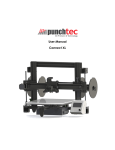
The User Manual of
Artifex
Desktop 3D Printer
http://3dmakerworld.com
Document date: January 6, 2014
(Check website for latest update)
CONTENTS
Contents
1 Introduction
1.1 Specifications . . . .
1.2 Safety . . . . . . . .
1.3 Acknowledgements .
1.4 Overview of chapters
.
.
.
.
.
.
.
.
.
.
.
.
.
.
.
.
.
.
.
.
.
.
.
.
.
.
.
.
.
.
.
.
.
.
.
.
.
.
.
.
.
.
.
.
.
.
.
.
.
.
.
.
.
.
.
.
.
.
.
.
.
.
.
.
.
.
.
.
.
.
.
.
.
.
.
.
2 Getting Started
2.1 Setting up software environment . . . . . . . . . . . . .
2.1.1 Installing electronics driver . . . . . . . . . . . .
2.1.2 Uploading firmware (Kit package only) . . . . .
2.1.3 Installing and configuring printing software . . .
2.2 Setting up printer hardware . . . . . . . . . . . . . . .
2.2.1 Checking mechanical motion (kit package only)
2.2.2 Leveling HBP . . . . . . . . . . . . . . . . . . .
2.2.3 Loading filaments . . . . . . . . . . . . . . . . .
2.3 Printing out your first 3D model . . . . . . . . . . . . .
3 Working with 3D Models
3.1 Getting 3D models . . . . . . . . . . . . . . . . . . . .
3.1.1 Creating your own 3D models . . . . . . . . . .
3.1.2 Downloading 3D models from online repositories
3.2 Generating G-code from 3D models . . . . . . . . . . .
3.2.1 Loading 3D models . . . . . . . . . . . . . . . .
3.2.2 Configuring Slic3r . . . . . . . . . . . . . . . . .
3.2.3 Slicing 3D models . . . . . . . . . . . . . . . . .
4 Printing with ABS Filaments
4.1 Configuring printing settings
4.1.1 The printer settings .
4.1.2 The slicing settings .
4.2 Preparing print surface . . .
5 Support
http: // 3dmakerworld. com
.
.
.
.
.
.
.
.
.
.
.
.
.
.
.
.
.
.
.
.
.
.
.
.
.
.
.
.
.
.
.
.
.
.
.
.
.
.
.
.
.
.
.
.
.
.
.
.
.
.
.
.
.
.
.
.
.
.
.
.
.
.
.
.
.
.
.
.
.
.
.
.
.
.
.
.
.
.
.
.
.
.
.
.
.
.
.
.
.
.
.
.
.
.
.
.
.
.
.
.
.
.
.
.
.
.
.
.
.
.
.
.
.
.
.
.
.
.
.
.
.
.
.
.
.
.
.
.
.
.
.
.
.
.
.
.
.
.
.
.
.
.
.
.
.
.
.
.
.
.
.
.
.
.
.
.
.
.
.
.
.
.
.
.
.
.
.
.
.
.
.
.
.
.
.
.
.
.
.
.
.
.
.
.
.
.
.
.
.
.
.
.
.
.
.
.
.
.
.
.
.
.
.
.
.
.
.
.
.
.
.
.
.
.
.
.
.
.
.
.
.
.
.
.
.
.
.
.
.
.
.
.
.
.
.
.
.
.
.
.
.
.
.
.
.
.
.
.
.
.
.
.
.
.
.
.
.
.
.
.
.
.
.
.
.
.
.
.
.
.
.
.
.
.
.
.
.
.
.
.
.
.
.
.
.
.
.
.
.
.
.
.
.
.
.
.
.
.
.
.
.
.
.
.
.
.
.
.
.
.
.
.
.
.
.
.
.
.
.
.
.
.
.
.
.
.
.
.
3
4
5
6
7
.
.
.
.
.
.
.
.
.
8
8
8
13
21
26
28
30
34
39
.
.
.
.
.
.
.
43
43
43
43
44
44
45
48
.
.
.
.
51
51
51
52
52
55
2
1 INTRODUCTION
1
Introduction
The 3DMakerWorld Artifex (Figure 1.1) is an open source desktop 3D printer. It makes
three-dimensional objects out of PLA and ABS filaments layer by layer. The printer’s frame
is based on the frame of MendelMax-2.0, and the design was heavily modified for printability, strength, wire management, vibration reduction, filament feeding, and compatibility
with other features in the extruder and heated build platform (HBP). The printer uses an
MakerGear hot-end and its compact extruder design. A durable 24v silicone rubber heater
is used in the HBP to achieve fast heating-up. The design of 3DMakerWorld Artifex 3D
Printer is open to the public under the Creative Commons Attribution-ShareAlike 3.0 Unported license (CC BY-SA 3.0).
Figure 1.1: The 3DMakerWorld Artifex 3D printer
http: // 3dmakerworld. com
3
1 INTRODUCTION
1.1
Specifications
Printing
Print technology
– Fused Filament Fabrication
Build space
– W × D × H: 230 × 310 × 190mm (9 × 12.2 × 7.5in)
– Volume: 13,547cm3 (827 in3 )
– Height extendable to 220mm (8.7in) in the middle of x-axis for additional 198
× 310 × 30mm (1,841cm3 , or 112in3 ) space
Layer resolution
– 0.05mm (0.002in)
Nozzle diameter
– 0.35mm (0.014in)
Print materials
– 1.75mm PLA and ABS
Speed
– Top print speed
∗ Infill or inner perimeter: 150mm/sec
∗ Outer perimeter: 100mm/sec
– Top non-print speed: 300mm/sec
Acceleration
– Top print acceleration:
∗ Infill: 3000mm/sec
∗ Perimeter: 1500mm/sec
– Top non-print acceleration: 3000mm/sec
Electrical
Power requirements
– 110/220 VAC
Electronics
– RAMBo
Hot-end
– MakerGear hot-end with 0.35mm nozzle
http: // 3dmakerworld. com
4
1 INTRODUCTION
Heated bed
– 24V 200W heated bed up to 120C
Cool fans
– Three 24V cooling fans for filament drive, print surface, and electronics
Mechanical
Overall dimension
– W × D × H: 484 × 482 × 480mm (19 × 19 × 19in)
Weight
– 11Kg (24lb)
Frame
– Aluminum extrusions
Motion
– X and Y axis: linear rails and GT2 belts
– Z axis: precision linear shafting and ACME leadscrews
Printed parts
– Black ABS
1.2
Safety
WARNING: The 3DMakerWorld Artifex 3D Printer generates high temperature and contains
fast moving mechanical parts which may cause injury or damage. Please follow the guidelines
carefully to operate the printer safely. 3D Maker World assumes no liability for any loss or
injury caused by operating the Artifex 3D Printer.
• Provide sufficient clear space around the printer to permit free motion of moving parts,
including the front-back movement of build platform, the up-down movement of X-axis
assembly, and the rotation of filament spool.
• When the printer is in operation, never touch moving parts, including belts, pulleys,
motor shafts, rail carriages, and lead screws.
• Never touch the extruder nozzle and heated bed without turning off the power and
allowing them to completely cool down.
• Always power off the printer and disconnect USB cable before any service or troubleshooting operation.
• Always discharge yourself by touching a grounded source before touching the electronics.
http: // 3dmakerworld. com
5
1 INTRODUCTION
• Never leave flammable materials near printer.
• Place the printer in a well-ventilated area for printing with ABS filaments.
1.3
Acknowledgements
As an open-source 3D printer, the 3DMakerWorld Artifex was designed with the inspiration
from many others’ work in the open source 3D printing community. We would like to address
our sincere acknowledgement to the following folks/groups for their great work, which has
inspired us in our design process:
• Makers Tool Works for the design of MendelMax 2.0
• kludgineer for the design of MendelMax 1.5: thingiverse.com/thing:20355
• MakerGear for the hot-end and extruder design
• Ultimachine for the creation of RAMBo electronics
• Ultibots for the design of power supply unit fan duct: thingiverse.com/thing:53876
• The RepRap community for the sharing of various 3D printing knowledge
The operation of Artifex 3D Printer is based on an open source software toolchain. We
want to thank people who have developed the following open source programs:
• Repetier-Host: the printing user interface
• Slic3r: G-code generator, included in the Repetier-Host
• Marlin: the firmware of 3D printer
• Arduino: used to upload and edit the firmware of Artifex 3D Printer
We would also like to thank makers for creating the following fantastic 3D models, which
we have printed out on the Artifex 3D Printer to demonstrate the machine capability:
• Torture Test by MAKE: thingiverse.com/thing:33902
• Surface Finish Test by whpthomas: thingiverse.com/thing:39050
• Cute Octopus by MakerBot: thingiverse.com/thing:27053
• Rubber Duck by willie: thingiverse.com/thing:139894
• Gear Vase by JelleAtProtospace: thingiverse.com/thing:19031
• Eiffel Tower by approx: thingiverse.com/thing:24068
http: // 3dmakerworld. com
6
1 INTRODUCTION
1.4
Overview of chapters
Chapter 2 will be focused on how to set up the software environment and the printer hardware
for printing using PLA filaments. By the end of Chapter 2, you will be able to print out
your first 3D model using a pre-generated g-code for the Artifex 3D printer.
Chapter 3 will discuss how to generate g-code from a 3D model of your choice, either
from your own creation or from an online 3D model repository. A few 3D modeling tools
and online 3D model repositories will be introduced. And the main content of Chapter 4
will be focused on the slicing settings of Slic3r.
Figure 1.2 shows the structure of Chapter 2 and 3.
Figure 1.2: Structure of Chapter 2 and 3
Chapter 4 will cover the printing parameter configuration and printer set-up for printing
with ABS filaments. Chapter 5 will list our support information for future assistance.
http: // 3dmakerworld. com
7
2 GETTING STARTED
2
Getting Started
2.1
Setting up software environment
The software set-up in this section is based on a Windows operating system. The similar steps
applies to set-ups for Mac or Linux based computers. All the software can be downloaded
on our website.
The set-up in this chapter The printing parameter configuration and printer
2.1.1
Installing electronics driver
Like other device drivers, the electronics driver of your 3D printer allows your computer to
recognize the printer when you connect it to the computer. The Artifex 3D Printer uses
the RAMBo electronics from Ultimachine. No installation is required for Mac and Linux
systems. The driver file for Windows, RAMBo USBdriver.zip, can be downloaded on our
website. Follow steps below to install the driver for Windows:
1. Download the driver and save it in a folder of your choice. In our case, we saved the
file on the desktop.
2. Unzip the compressed file using 7-Zip or other archive programs. (Figure 2.1)
Figure 2.1: Unzip the driver file using 7-Zip
3. Connect the printer to your computer via the provided USB cable. At the first time of
connecting Artifex to your computer, your computer will likely fail to allocate a driver
for the hardware to work correctly. We will manually update the device driver.
http: // 3dmakerworld. com
8
2 GETTING STARTED
4. Open the Device Manager under ”Control Panel → System and Security → System”.
Under ”Other devices”, you will find the RAMBo device, right click and select ”Update
Driver Software...”. (Figure 2.2)
Figure 2.2: Update driver software
5. A window will pop up, asking whether to ”Search automatically...” or ”Browse my
computer...”. Select ”Browse my computer...” (Figure 2.3)
http: // 3dmakerworld. com
9
2 GETTING STARTED
Figure 2.3: Select “Browse my computer...”
6. In the popped up window, select the folder where you unzipped the archive file. In
our case, the location is ”C:\Desktop\RAMBo USBdriver”. Then, click ”Next”. (Figure 2.4)
http: // 3dmakerworld. com
10
2 GETTING STARTED
Figure 2.4: Allocate the location of driver file
7. A security window may pop up (Figure 2.5). If so, click ”Install”.
Figure 2.5: Confirm software installation
8. After the installation, you will be noticed that ”Windows has successfully updated
your driver software”. Click ”Close”. (Figure 2.6)
http: // 3dmakerworld. com
11
2 GETTING STARTED
Figure 2.6: Installation completed successfully
9. Now, the RAMBo electronics will appear under the ”Ports (COM & LPT)”. Write
down the COM port which the electronics uses. We will need this information later
when setting up the printing software. In our case, it is COM3. (Figure 2.7)
http: // 3dmakerworld. com
12
2 GETTING STARTED
Figure 2.7: COM port used by the electronics board
2.1.2
Uploading firmware (Kit package only)
The firmware of your 3D printer is like the operating system of your computer. The Artifex
3D Printer uses a customized Marlin-based firmware.
• For a fully assembled Artifex 3D Printer, its firmware is already loaded before the
shipment. You can skip this section. In the future, if you need to update the firmware
for your Artifex 3D Printer, please follow steps listed in this section.
• For an Artifex 3D Printer kit, after you install the electronics, you need to upload its
firmware.
1. Download the Arduino software
The RAMBo electronics used in your Artifex 3D Printer is an Arduino-compatible control board. The Arduino integrated development environment (IDE) software will be
installed on your computer to communicate with the printer electronics. The Arduino
IDE software runs on Windows, Mac OS X, and Linux, and can be downloaded from
http: // 3dmakerworld. com
13
2 GETTING STARTED
http://arduino.cc/en/Main/Software. The following steps are based on the current
Arduino 1.0.5 released version for Windows.
• Download the Zip file of Arduino software (arduino-1.0.5-windows.zip), and
save it to your computer’s Desktop or a location of your choice.
• Unzip the file using 7-Zip or other archive software (Figure 2.8). The unzipped
files will appear in a folder named “arduino-1.0.5”.
Figure 2.8: Unzip the Arduino zip file using 7-Zip
• Open the folder and there is a file named “arduino.exe” (Figure 2.9). It is
the executable program of the Arduino IDE software. No further installation is
needed.
http: // 3dmakerworld. com
14
2 GETTING STARTED
Figure 2.9: The unzipped Arduino 1.0.5 files
2. Upload the firmware of Artifex 3D Printer
The Artifex 3D Printer is shipped with a customized Marlin-based firmware.
• Download the Artifex firmware from http://3dmakerworld.com/support/downloads,
save it to your computer’s Desktop or a location of your choice.
• Unzip the file using 7-Zip or other archive software. (Figure 2.10)
http: // 3dmakerworld. com
15
2 GETTING STARTED
Figure 2.10: Unzip the Artifex firmware zip file using 7-Zip
• Open the Arduino IDE software, arduino.exe. The software interface is shown in
Figure 2.11.
Figure 2.11: The Arduino IDE software
http: // 3dmakerworld. com
16
2 GETTING STARTED
• Click “File → Open...” (Figure 2.12).
Figure 2.12: Open files in the Arduino IDE software
• Select the file “Marlin.ino” in the unzipped Artifex firmware file folder
“C:\Desktop\ArtifexFirmware1.0\Marlin” (Figure 2.13), and click “Open”. Figure 2.14 shows the Arduino IDE with opened Artifex firmware files.
Figure 2.13: The main file of Artifex firmware “Marlin.ino”
http: // 3dmakerworld. com
17
2 GETTING STARTED
Figure 2.14: The Arduino IDE with opened Artifex firmware files
• Select “Tools → Board → Arduino Mega 2560 or Mega ADK”. (Figure 2.15)
Figure 2.15: Select the board type of Artifex electronics
• Select “Tools → Serial Port → COM3”. (Figure 2.16)
http: // 3dmakerworld. com
18
2 GETTING STARTED
Figure 2.16: Select the serial port of Artifex electronics
• Select “File → Upload” to upload the Artifex firmware to its electronics (Figure 2.17). Before uploading, the Arduino IDE will first compile the firmware files.
The progress of compiling and uploading is shown in the bottom status window.
http: // 3dmakerworld. com
19
2 GETTING STARTED
Figure 2.17: Upload the Artifex firmware
• If the uploading is successful, you will see the message of “Done uploading” in
the bottom status window (Figure 2.18). If the compiling or uploading is not
successful, the error message will be shown in the status window as well. Common
causes of uploading failure include: wrong Arduino board type, wrong serial port,
or serial port conflict (e.g., the same serial port is used by your printing software,
which will be covered later in this section). For other error message, please refer
to the Arduino manual or contact our technical support.
http: // 3dmakerworld. com
20
2 GETTING STARTED
Figure 2.18: Firmware uploading done successfully
2.1.3
Installing and configuring printing software
A printing software provides the user interface to operate your 3D printer. We recommand
the Repetier-Host printing software due to its user-friendly interface and all-in-one features.
Repetier-Host can work on Windows, Mac, and Linux systems. The following steps are based
on the Windows version 0.90C.
1. Download the Repetier-Host set-up file from http://www.repetier.com/download/.
2. Run the set-up file to install the Repetier-Host software. After the installation, open
the Repetier-Host. (Figure 2.19)
http: // 3dmakerworld. com
21
2 GETTING STARTED
Figure 2.19: The Repetier-Host interface
3. Configure the Repetier-Host for your Artifex 3D Printer.
• Open the Printer Settings from “Config → Printer Settings” (Figure 2.20).
Figure 2.20: Open the Printer Settings
• In the window of Printer Settings (Figure 2.21), enter the printer name “Artifex”
on the top, and configure settings on the “Connection” page as shown in the
figure. Make sure the port number matches the serial number used by your Artifex
3D Printer.
http: // 3dmakerworld. com
22
2 GETTING STARTED
Figure 2.21: Printer Settings: Connection
• Configure the settings on the “Printer” page (Figure 2.22). Depending on your
printing materials, the default temperature of extruder and heated bed can be set
to either 180C/70C (PLA), or 220C/95C (ABS).
http: // 3dmakerworld. com
23
2 GETTING STARTED
Figure 2.22: Printer Settings: Printer
• Configure the settings on the “Printer Shape” page. (Figure 2.23)
Figure 2.23: Printer Settings: Printer Shape
• Configure the settings on the “Advanced” page. Nothing to change on the page.
http: // 3dmakerworld. com
24
2 GETTING STARTED
Just click “OK” and the Repetier-Host is ready to use with your Artifex 3D
Printer. (Figure 2.24)
Figure 2.24: Printer Settings: Advanced
• Click the drop-down arrow next to the “Connect” button, and select “Artifex”
(Figure 2.25). The Repetier-Host is now connected with your Artifex 3D Printer,
as confirmed by the message shown on the bottom status bar (Figure 2.26).
http: // 3dmakerworld. com
25
2 GETTING STARTED
Figure 2.25: Connecting with Artifex 3D Printer
Figure 2.26: The Repetier-Host connected with Artifex 3D Printer
2.2
Setting up printer hardware
Caution: Before powering up your Artifex 3D Printer, check the voltage selection of the
Power Supply Unit (PSU) on the bottom left of your Artifex 3D Printer, and make sure it
matches the voltage supply in your area. (Figure 2.27)
http: // 3dmakerworld. com
26
2 GETTING STARTED
Figure 2.27: Voltage selection of PSU
Insert the power cord into the AC input receptacle on the back of your Artifex 3D Printer.
Plug the power cord into an electrical outlet, and turn on the power switch next to the AC
input receptacle. (Figure 2.28)
Figure 2.28: Power connection and switch
http: // 3dmakerworld. com
27
2 GETTING STARTED
2.2.1
Checking mechanical motion (kit package only)
The mechanical movement has been checked in a fully assembled Artifex 3D printer. The
process listed in this section is only needed if you are assembling your own Artifex 3D
printer from a kit package, although information provided here can help you gain better
understanding of your Artifex 3D printer even you start with a fully assembled Artifex.
Figure 2.29 shows the X/Y/Z-axis definition of your Artifex 3D Printer. The extruder
moves along the X- and Z-axis, and the heated build platform (HBP) moves along the Y-axis.
The extruder’s X/Y/Z position is defined relative to the HBP.
Figure 2.29: X/Y/Z-axis definition of Artifex 3D Printer
Figure 2.30 shows commands in the Manual Control page of Repetier-Host for mechanical
movement.
http: // 3dmakerworld. com
28
2 GETTING STARTED
Figure 2.30: Manual control commands for checking X/Y/Z-axis motion
Step 1 Checking moving directions
Use the X/Y/Z arrow commands to test the moving direction of extruder and HBP.
If either one moves in a wrong direction along X/Y/Z-axis, open the electronics case
by taking off its top cover to check the connection of motor cables on the electronics
board. The red wire of motor cable should face towards the front of printer (Figure
2.31).
Caution:
1. Make sure there is enough distance for the extruder/HBP to move freely without
bumping onto the frame/HBP before sending out a control command.
2. Power off the printer and unplug the USB cable before you open the electronics
case or flip the connector of any motor cable.
3. When opening the electronics case, be careful not to break the cable of electronics
fan, which is mounted on the top cover of electronics case.
http: // 3dmakerworld. com
29
2 GETTING STARTED
Figure 2.31: Connection of step motor cables (red wire: facing front)
Step 2 Checking homing functions
The X/Y/Z mechanical endstops are installed at the x = 0, y = 0, and z = 0 position,
respectively. During homing, whenever the X/Y/Z endstop is triggered, the motor(s)
in that axis will be stopped and the position of extruder’s nozzle tip will be registered
as the origin of that axis.
• Click the “Home X” icon. The extruder will move to the left until it triggers the
X-axis endstop.
• Click the “Home Y” icon. The HBP will move backwards untill it triggers the
Y-axis endstop.
• Z-axis homing will be tested in the next section when leveling HBP.
2.2.2
Leveling HBP
A 3D object is formed layer by layer by extruding the melt filament onto the last layer of
object. The first layer of object is directly printed onto the printing surface. In order to
http: // 3dmakerworld. com
30
2 GETTING STARTED
achieve successful and high-quality printing, it is very important to set a proper distance
between the nozzle tip and the HBP across the entire printing surface at the start of printing.
• If the nozzle tip is too far from the HBP, the print will not stick well to the printing
surface.
• If the nozzle tip is too close to the HBP, the extrusion flow may be blocked during
printing, and the nozzle tip may scratch the HBP or previous layers of print.
At the z = 0 position, a recommended distance between the nozzle tip and the HBP for
most printing tasks is 0.1mm, which is about the thickness of a piece of thin paper.
Step 1 Preparation
• Click the “Turn Motor Off” button on the Manual Control page of Repetier-Host
interface (Figure 2.30) to turn off power of all motors so you can perform manual
operation in the following steps.
• Check if X-axis is level with the frame. Measure the distance between the X-axis
rail and the top motor mount on both left and right sides (Figure 2.32). If these
two measurements are different, manually turn either left or right motor shaft
coupler to raise/lower the X-axis on one side to match with the height of another
side.
Figure 2.32: Checking the levelness of X-axis
• Adjust the 3-point bed leveling thumb screws to let the bottom of hex screw be
flush with the bottom of thumb screw (Figure 2.33). This operation is to ensure
http: // 3dmakerworld. com
31
2 GETTING STARTED
that the 3-point leveling thumb screws will have enough up/down adjusting room
for HBP leveling.
Figure 2.33: The bottom of thumb screw being flush with the bottom of hex screw
Step 2 Zeroing Z-axis
• Manually move the extruder to the middle of X-axis and the HBP to the middle
of Y-axis so the extruder’s nozzle tip points towards the center of HBP.
• Use the “-Z” arrow commands to carefully lower the extruder to get it close to
the HBP.
• Adjust the Z-axis endstop trigger screw in the back of right X-end (Figure 2.34)
so the extruder’s nozzle tip almost touches the HBP when the Z-axis endstop is
triggered. You may need to raise and home the Z-axis several times to finish this
step.
http: // 3dmakerworld. com
32
2 GETTING STARTED
Figure 2.34: Z-axis endstrop and the adjustable trigger screw
Step 3 Leveling HBP
• Manually move the extruder to the middle of HBP left edge.
• Slide the 0.1mm feeler gauge provided in your Artifex package, or a piece of thin
paper, between the nozzle tip and the HBP.
• Adjust the left leveling thumb screw until the feeler gauge, or the paper, can just
slide between the nozzle and the HBP with some resistance.
• Manually move the extruder to the right-front corner of HBP. Adjust the rightfront leveling thumb screw until the feeler gauge, or the paper, can just slide
between the nozzle and the HBP with some resistance.
• Manually move the extruder to the right-rear corner of HBP. Adjust the right-reat
leveling thumb screw until the feeler gauge, or the paper, can just slide between
the nozzle and the HBP with some resistance.
• Repeat the above steps for 2-3 times to ensure the HBP is level. After the HBP
leveling, the distance between nozzle tip and the HBP is about 0.1mm across the
print surface. (Figure 2.35)
http: // 3dmakerworld. com
33
2 GETTING STARTED
Figure 2.35: Position of nozzle tip after HBP leveling
Note:
1. Do not be confused with the 3-point thumb screws in the middle of Y-axis mount
plate and the bed tightening screws in the four corners of HBP. (Figure 2.36)
Figure 2.36: HBP thumb screws
2. When adjusting the 3-point thumb screws, you may feel it is very tight to turn
the screws. This is normal. The Artifex 3D Printer uses quite strong wave springs
for bed leveling to prevent the screw to get loose during printing.
2.2.3
Loading filaments
Step 1 Feeding filament through the filament guide tube
Free the end of filament from the filament spool, and cut off the bent section used to
secure the filament to the spool. Feed the filament into the rear end of filament guide
http: // 3dmakerworld. com
34
2 GETTING STARTED
tube (Figure 2.37), and push it through the tube until it reaches the filament drive in
the front end of filament guide tube.
Figure 2.37: Feeding filament through the filament guide tube
Step 2 Heating up extruder
On the “Manual Control” page of Repetier-Host, there is an “Extruder” section (Figure
2.38). After the Repetier-Host is connected with your Artifex 3D printer, the extruder
target temperature shows 180◦ C as we set in Chapter 2. Click the “Heat Extruder”
button to heat up the extruder to the target.
Figure 2.38: Extruder control commands on Repetier-Host interface
http: // 3dmakerworld. com
35
2 GETTING STARTED
The Repetier-Host provides a nice temperature monitoring interface. First, configure
the information you would like to monitor under the “Temperature” manu (Figure
2.39). Then, on the left side of the Repetier-Host, select the “Temperature Curve”
page to display the temperature information (Figure 2.40).
Figure 2.39: Top menu for temperature monitoring on Repetier-Host interface
http: // 3dmakerworld. com
36
2 GETTING STARTED
Figure 2.40: Temperature monitoring screen on Repetier-Host interface
Step 3 Extruding filament through the extruder
• Once the extruder temperature reaches a steady state at the target of 180◦ C, pop
up the filament guide tube from the filament drive, and gently push the filament
into the filament drive. (Figure 2.41)
http: // 3dmakerworld. com
37
2 GETTING STARTED
Figure 2.41: Feeding filament into filament drive
• Click the “↓” command on the Repetier-Host interface (Figure 2.38) to extrude
50mm of filament through the filament drive at the speed of 100mm/min.
• Continue gently pushing the filament downwards until you feel the pulling from
the extruder motor.
• If needed, click the “↓” command again to extrude out more filament until you
see a steady stream of melt filament extruded out of the extruder nozzle. (Figure
2.42)
http: // 3dmakerworld. com
38
2 GETTING STARTED
Figure 2.42: Extruded melt filament
2.3
Printing out your first 3D model
In this section, you will print out a 3D model from a pre-generated G-code file. The G-code
file contains a list of instructions to control your Artifex 3D printer to make a 3D model
layer by layer. Chapter 4 will discuss how to generate the g-code from a 3D model file to
print out any 3D model of your choice.
1. Before your printing, clean the print surface using 91% rubbing alcohol (Figure 2.43)
with a piece of paper towel. The 91% rubbing alcohol is available in most local grocery
stores.
http: // 3dmakerworld. com
39
2 GETTING STARTED
Figure 2.43: 91% alcohol for cleaning print surface
2. Download a G-code file, for example “CuteOcto PLA.gcode”, from our website, and
save it to your computer’s Desktop or a location of your choice.
3. On the Repetier-Host interface, click the “Load” button on the top menu bar (Figure
2.44). Locate the downloaded file “CuteOcto PLA.gcode” and open it.
Figure 2.44: Loading file from the Repetier-Host interface
4. The Repetier-Host interface with the loaded file is shown in Figure 2.45.
http: // 3dmakerworld. com
40
2 GETTING STARTED
Figure 2.45: The Repetier-Host interface with loaded G-code
5. Click the “Run Job” button on the top menu bar (Figure 2.46). The printer will follow
the instructions in the G-code to initialize its position and heat up the extruder and
HBP. Once both the extruder and HBP reach their target temperature, the printer
will start the print job.
Figure 2.46: Running print job from the Repetier-Host interface
6. After the print job is done, you will get your first 3D model printed out from your
Artifex 3D model (Figure 2.47). Wait until both the extruder and HBP completely
cool down before you take off the print off the HBP.
http: // 3dmakerworld. com
41
2 GETTING STARTED
Figure 2.47: Printed cute octopus 3D model
http: // 3dmakerworld. com
42
3 WORKING WITH 3D MODELS
3
Working with 3D Models
In this chapter, we will discuss how to generate the G-code for your Artifex 3D Printer from
a 3D model of your choice, either downloaded from an online 3D model repository or created
by your own. Discussion in this chapter is based on printing with PLA filaments. Printing
with ABS filaments will be covered in the next Chapter.
3.1
3.1.1
Getting 3D models
Creating your own 3D models
A 3D model can be created by various 3D modeling software. Some examples include:
Free 3D modeling software:
• OpenSCAD: http://www.openscad.org
• Blender: http://www.blender.org
• SketchUp: http://www.sketchup.com
• FreeCAD: http://www.freecadweb.org
• Tinkercad: http://www.tinkercad.com
Commercial 3D modeling software:
• SolidWorks: http://www.solidworks.com
• AutoCAD: http://www.autodesk.com
R
• Alibre (now Geomagic
): http://www.alibre.com
3.1.2
Downloading 3D models from online repositories
You can also download 3D models from online repositories, for example,
• Thingiverse: http://www.thingiverse.com
• GrabCAD: http://www.grabcad.com
A 3D model can be saved in different file formats. The STereoLithography (STL) format
is a format widely used for 3D printing. In the following discussion, it is assumed that the
3D model you created or downloaded is already saved in a STL file format.
http: // 3dmakerworld. com
43
3 WORKING WITH 3D MODELS
3.2
Generating G-code from 3D models
After you get a 3D model, you need to slice it into horizontal layers for your Artifex 3D
Printer to print it out layer by layer. The instructions which command your Artifex 3D
Printer to do the layer-by-layer printing are saved in a G-code file. The translation from a
digital 3D model into a G-code file is processed by a slicing program called slicer. Slic3r
(http://www.slic3r.org) is the slicer recommended for your Artifex 3D Printer, and it has
been integrated in the Repetier-Host interface. This section will guide you through the
process to use Slic3r to generate the G-code file from a 3D model of your choice in the
Repetier-Host interface.
3.2.1
Loading 3D models
1. Download the STL file (CuteOcto.stl) for the cute octopus model from our website,
and save it to your computer’s Desktop or a location of your choice.
2. On the Repetier-Host interface, click the “Load” button on the top menu bar. Locate
the downloaded file “CuteOcto.stl” and open it.
3. Once the loading is completed, the 3D model will be displayed on the left “3D View”
window, where you can rotate, zoom, move the model to view the 3D model. The
“Object Placement” page on the right side listed the file name of loaded 3D model,
available placement operations, and some model information. (Figure 3.1)
http: // 3dmakerworld. com
44
3 WORKING WITH 3D MODELS
Figure 3.1: Repetier-Host with loaded 3D model CuteOcto.stl
3.2.2
Configuring Slic3r
• Click the “Slicer” page next to the “Object Placement” page on the right side of
Repetier-Host interface. On the top of the “Slicer” page is the option for the Sli3r
slicer program (Figure 3.2).
http: // 3dmakerworld. com
45
3 WORKING WITH 3D MODELS
Figure 3.2: Slicer page on the Repetier-Host interface
• Click the “Configure” button in the “Slic3r” section, and a window will pop up showing
the Slic3r program (Figure 3.3).
Figure 3.3: Slic3r program window
http: // 3dmakerworld. com
46
3 WORKING WITH 3D MODELS
Slicing settings in Slic3r are organized into three sections: Print Settings, Filament Settings, and Printer Settings. The detailed explanation of all parameters in these sections is
available from the Slic3r Manual (http://manual.slic3r.org/). Some configuration examples
are provided on our website for you to start with your Artifex 3D Printer. The process below
shows how to import such configuration files into Slic3r to slice your 3D models. Once you
get more familiar with the Slic3r program and the printing process, you can tweak slicing
parameters to meet your specific needs for different models.
• Download a slicing configuration file, for example Artifex PLA.ini, from our website,
and save it to your computer’s Desktop or a location of your choice.
• In the Slic3r program window, click “File → Load ConFigure ..” (Figure 3.4), and
select the downloaded file Artifex PLA.ini.
Figure 3.4: Loading a configuration file in Slic3r
• On the “Print Settings” page, click the “Save” icon button next to the configuration file
name “Artifex PLA.ini”. A window will pop up for you to enter the name of current
Print Settings (Figure 3.5). Here, we just use the same name as the configuration file
“Artifex PLA”. Then, click “OK”. Do the same to save filament settings and printer
settings under the name “Artifex PLA”. Then, close the Slic3r program window.
http: // 3dmakerworld. com
47
3 WORKING WITH 3D MODELS
Figure 3.5: Saving print settings in Slic3r
3.2.3
Slicing 3D models
• On the Slicer page of Repetier-Host interface, select “Artifex PLA” for Print Settings,
Printer Settings, and Filament Settings (Extruder 1) in Slic3r section. (Figure 3.2)
• Click the “Slice with Slic3r” button, and a window will pop up showing the slicing
progress (Figure 3.6).
Figure 3.6: Slicing information window
http: // 3dmakerworld. com
48
3 WORKING WITH 3D MODELS
• Once the slicing is completed, the Repetier-Host will look like what shown in Figure 3.7,
which is the same as what you saw in the last chapter when you directly loaded a pregenerated G-code file.
Figure 3.7: Repetier-Host interface at the completion of model slicing
The Repetier-Host program provides an excellent capability to visualize the generated
G-code of your 3D models. There are three options for visualization (Figure 3.2): Show
Complete Code, Show Shingle Layer, and Show Layer Range. For example, you can preview
what the first layer of print will look like (Figure 3.8). When configuring your own slicing
settings, this visualization feature will become very handy to check the slicing result before
sending the job to your 3D printer.
http: // 3dmakerworld. com
49
3 WORKING WITH 3D MODELS
Figure 3.8: Previewing the first layer of print in Repetier-Host
http: // 3dmakerworld. com
50
4 PRINTING WITH ABS FILAMENTS
4
Printing with ABS Filaments
Printing with ABS filaments is very similar to printing with PLA filaments. The major
differences for printing with ABS are:
• It requires higher temperature for both extruder and HBP, and
• The print surface needs to be covered by print tapes for the print to better stick to the
HBP.
4.1
Configuring printing settings
Two configurations in Repetier-Host need to be changed to work with ABS filaments: the
printer settings, and the slicing settings.
4.1.1
The printer settings
The printer settings for printing with PLA filaments are shown in Section 2.1.3. For printing
with ABS filaments, the only difference will be the default extruder and heated bed temperatures. Change the Default Extruder Temperature to 220◦ C, and the Default Heated Bed
Temperature to 95◦ C. (Figure 4.1)
Figure 4.1: Printer Settings in Repetier-Host for printing with ABS
http: // 3dmakerworld. com
51
4 PRINTING WITH ABS FILAMENTS
4.1.2
The slicing settings
Download the slicing configuration file, Artifex ABS.ini, from our website. Then, follow the
steps in Sections 3.2.2 to update slicing settings for printing with ABS filaments. The main
difference from the settings for printing with PLA filaments are:
Print settings A brim of 2mm width is added for the print to better stick to the print
surface. (Note: The brim needs to be cut or teared off from the print after it is
finished and removed from the print surface. After removing the brim, you may see
some rough surface on the object along the cutting line. For small size objects, you
can print them out without brims for better surface finish.)
Filament settings Both extruder and bed are set at higher temperatures, and cooling is
turned off for printing with ABS filaments.
Printer settings In the Custom G-code, higher extruder and bed temperature are set
before the printing starts.
4.2
Preparing print surface
After extruded from the nozzle, ABS filaments can stick well to warm and clean print tapes.
Both PET tapes and Kapton tapes can be used for this purpose. PET tapes are easier to
be applied on the glass surface, and can last longer than Kapton tapes, while Kapton tapes
can provide stronger attachment to the print. In the following, we use a PET tape as the
example.
1. Taking off glass plate
(a) Loose thumb screws under the four HBP corners. (Figure 2.36)
(b) Slide printed HBP corners outward away from the bed to release the glass top
from the build platform. (Figure 4.2)
(c) Carefully take off the glass top and place it on a flat table surface.
http: // 3dmakerworld. com
52
4 PRINTING WITH ABS FILAMENTS
Figure 4.2: Releasing glass plate from the HBP
2. Applying PET tape on glass plate
There are many online tutorials on how to apply PET or Kapton tapes on glass plates
without bubbles. An often mentioned method is a “wet” method, where a thin layer
of water or soap water is applied before applying the tape to the glass plate. In our
process, we prefer a “dry” method for less clean-up afterwards. The main steps in our
process are similar to what introduced by Josef Prusa in his video, How to prepare
heatbed surface, although we do not use the sanding and applying “ABS juice” steps
shown in his video. Instead, we clean the print tape surface using 91% rubbing alcohol
in the end. The 3DMakerWorld Artifex 3D Printer comes with a 3-point leveling
system and adjustable Z-axis zeroing capability, which help achieve a leveled build
platform with its height fine tuned. In our experience, such leveled platform, together
with a clean and heated tape surface, is able to let ABS stick well to the print surface
without messing with Acetone for “ABS juice”. Please check Section 2.2.2 for how to
level the build platform.
(a) Place the glass plate on a flat table surface.
(b) Clean the glass surface with Windex or rubbing alcohol before applying the tape.
(c) Repeat the following steps to apply the PET tape strip by strip to cover the entire
glass plate as shown in Josef Prusa’s video, How to prepare heatbed surface. You
can apply some tape to secure the glass on the table while working through the
process.
Positioning PET tape Carefully position a strip of PET tape, which is 2 inch
wide and about 13 inch long in our case, along the edge of glass plate or the
edge of last strip to cover the glass surface without overlapping.
http: // 3dmakerworld. com
53
4 PRINTING WITH ABS FILAMENTS
Lifting PET tape While holding down one end of the tape, lift another end up
approaching the fixed end. Keep the tape stretched while lifting.
Removing air bubbles While holding the lifted end firmly, use a piece of paper
towel or a credit card to press the tape down little by little starting from the
fixed end, and to remove the air bubbles between the tape and the glass plate.
Continue through the tape.
(d) Trim off tape along the glass edges using a scissor or craft knife. (Caution: Be
careful of the sharp edges of scissors or knives.)
3. Installing glass plate
(a) Carefully place the tape covered glass plate back to the build platform on the top
of aluminum heat spreader.
(b) Slide printed HBP corners inward to secure the glass plate into the slots of HBP
corners.
(c) Tight up the thumb screws under the four HBP corners to hold them in place.
4. Cleaning print surface A clean surface is very important for the print to stick well
to the print tape. Clean the PET tape using 91% rubbing alcohol (Figure 2.43) with
a piece of paper towel.
Figure 4.3 shows the finished HBP with a PET tape covered glass plate.
Figure 4.3: The HBP with a PET tape covered glass plate
http: // 3dmakerworld. com
54
5 SUPPORT
5
Support
If you experience any difficulty when operating the Artifex 3D Printer, please contact us at:
• Email: [email protected]
• Phone: (913)897-8359
• Submit your questions: http://www.3dmakerworld.com/contacts
For updates of software/documents and other technical support topics, please visit us at
http://www.3dmakerworld.com/support.
Please review the Build Instructions (Figure 5.1) if you are building the Artifex 3D
Printer from a DIY kit.
Figure 5.1: The Build Instructions of Artifex 3D Printer
Thanks for your purchase of 3DMakerWorld Artifex 3D Printer.
Enjoy your printing!
http: // 3dmakerworld. com
55