1
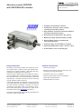
Absolute encoder TBD/TRD
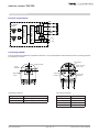
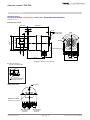
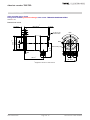
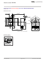
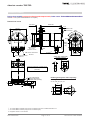
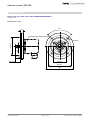
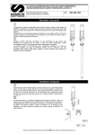
Installation drawing
Design form 58 with synchroniser flange and campled shaft, Order name: TRD58-SRA4096R4096C2ZD01
Shaft ø 12 mm (other shaft diameters on request)
Dimensions in mm
89 ±0.5***
18.8 ±0.5
ca. 5
3
6
4
70 ±0.1
Diagnosis LEDs
Access to the
preset button
120°
ø 50 f7
ø 58
+0.1
*
M4x8
Clamped shaft
Di = 12 H7
Insertion: 16 mm
EMC screw connections
M12x1.5
EMC screw connections
M16x1.5
ca. 57
Shaft
sealing
ring
ø50
ca. 70.5***
42 ±0.1
Clamp ring (Aluminium)
(in scope of delivery)
30
8
15
Maximum shaft length circulation of the
torque support arm = 23,2 mm +0,2 mm
(as shown)
PA locking washer
Torque support arm
(please order separatly)
Ordering code: ZRH-A-12-X
X = 6, 6,35, 8, 9,53, 10
19.5
**
Reducing bush (please order separatly)
8
X
12
7.2
9.3
Height adapter
* 2x screws DIN 912 M4x30 (VA) plus 2x lock washer (VA) plus 2x washer DIN 9021-4.3.
** 3x screws DIN 912 M4x10 (VA) plus 3x lock washer (VA).
*** singleturn version 14 mm shorter
Date: 30.04.2015
Page 11 of 12
Document no. TRD 11868 KE