1
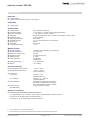
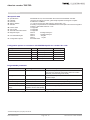
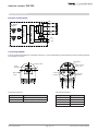
Absolute encoder TBD/TRD Technical Data Input data * 4 bytes position 4 bytes velocity (firmware version 1.02 or higher) Output data * 4 bytes preset Electrical data n Sensor system: n Operating voltage: n Power consumption: n Auflösung: n Measuring range: nTotal number of steps: nAbsolute accuracy: n Output code: n Code path: n Internal updating time ASIC with HALL elements + 13.5 VDC to + 30 VDC (reverse voltage protection) < 2 W, switch on current < 250 mA Resolution:4096 steps / 360°<) (12-bit) or 8192 steps / 360°<) (13-bit) 4096 revolutions Max. 25-bit ± 0.2 % (with reference to one revolution) Binary CW / CCW ≤ 2 ms Mechanical data n Operating speed: n Angular acceleration: n Moment of inertia (rotor): n Operating torque: n Starting torque: n Perm. shaft load: n Bearing service life **: n Weight: 1000 rpm max. (optionally up to 4000 rpm) 105 rad/s² max. 20 gcm² ≤ 8 Ncm (at 500 rpm) ≤ 4 Ncm 250 N axial 250 N radial > 109 revolutions ca. 0.450 kg Environmental data Operating temperature range: Storage temperature range: Resistance: To shock: To vibration: EMC standards: Protection type: (DIN EN 60529) - 40°C to + 85°C - 20°C to + 60°C (due to packaging) 500 m/s²; 11 ms DIN EN 60068-2-27 500 m/s²; 10 ... 2000 Hz DIN EN 60068-2-6 EN 61000-6-2 (interference immunity) EN 61000-6-4 (interference emission) (only with shielded connection cables) IP 66, IP 69K (on request) Electrical connections Connecting cap with threaded cable connections for: Supply voltage (+ UB = 24 VDC, - UB = 0 VDC), threaded cable connection M12x1.5 Bus in (A, B), threaded cable connection M16x1.5 Bus out (A‘, B‘), threaded cable connection M16x1.5 * ** These values apply at maximum shaft load. Higher values are achievable at lower loads. From the point of view of the control system. Date: 30.04.2015 Page 2 of 12 Document no. TRD 11868 KE