1
Absolute encoder TBD/TRD
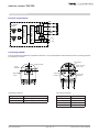
Electrical connection
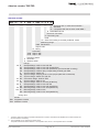
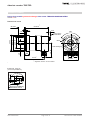
Principle circuit diagram
VP
N
S
ST
N
S
B
galvanic isolation
Controller
MT
PROFIBUS Controller
Hall - Sensor
Magnet
DC
A
DGND
DC
+ VS
- VS
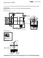
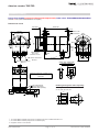
Connecting cap ZKD
The cap is listed and supplied as a separate order item. It can be separated from the absolute encoder for setting purposes
by releasing two screws.
DIP switches
Diagnosis LED‘s
Sub D connector
15 pin socket
Presetpushbutton
UB
SRD
C
Err
TWK-ELEKTRONIK
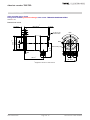
M3 mounting
screws
Connection
terminal 1
DÜSSELDORF
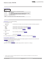
Connection terminal 1:
1
2
1
2
3
4
+ UB A
B A´ B´
Connection
terminal 2
Connection terminal 2:
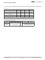
Designation
Signal
Designation
Signal
UB+
Supply voltage (24 VDC)
A
RXD/TXD-N
UB-
GND (0 VDC)
B
RXD/TXD-P
A'
RXD/TXD-N
B'
RXD/TXD-P
Date: 30.04.2015
Page 4 of 12
Document no. TRD 11868 KE