1
BL20 –
USER MANUAL
FOR
PROFINET
All brand and product names are trademarks or registered trade marks of the owner
concerned.
Edition 11/2008
© Hans Turck GmbH, Muelheim an der Ruhr
All rights reserved, including those of the translation.
No part of this manual may be reproduced in any form (printed, photocopy, microfilm or any
other process) or processed, duplicated or distributed by means of electronic systems
without written permission of Hans Turck GmbH & Co. KG, Muelheim an der Ruhr.
Subject to alterations without notice
Warning!
Before commencing the installation
Disconnect the power supply of the device.
Ensure that devices cannot be accidentally restarted.
Verify isolation from the supply.
Earth and short circuit.
Cover or enclose neighboring units that are live.
Follow the engineering instructions of the device concerned.
Only suitably qualified personnel in accordance with EN 50 110-1/-2 (VDE 0 105 Part 100)
may work on this device/system.
Before installation and before touching the device ensure that you are free of electrostatic
charge.
The functional earth (FE) must be connected to the protective earth (PE) or to the potential
equalization. The system installer is responsible for implementing this connection.
Connecting cables and signal lines should be installed so that inductive or capacitive interference do not impair the automation functions.
Install automation devices and related operating elements in such a way that they are well
protected against unintentional operation.
Suitable safety hardware and software measures should be implemented for the I/O interface so that a line or wire breakage on the signal side does not result in undefined states
in the automation devices.
Ensure a reliable electrical isolation of the low voltage for the 24 volt supply. Only use
power supply units complying with IEC 60 364-4-41 (VDE 0 100 Part 410) or HD 384.4.41
S2.
Deviations of the mains voltage from the rated value must not exceed the tolerance limits
given in the specifications, otherwise this may cause malfunction and dangerous operation.
Emergency stop devices complying with IEC/EN 60 204-1 must be effective in all operating modes of the automation devices. Unlatching the emergency-stop devices must not
cause restart.
Devices that are designed for mounting in housings or control cabinets must only be operated and controlled after they have been installed with the housing closed. Desktop or
portable units must only be operated and controlled in enclosed housings.
Measures should be taken to ensure the proper restart of programs interrupted after a
voltage dip or failure. This should not cause dangerous operating states even for a short
time. If necessary, emergency-stop devices should be implemented.
Wherever faults in the automation system may cause damage to persons or property,
external measures must be implemented to ensure a safe operating state in the event of a
fault or malfunction (for example, by means of separate limit switches, mechanical interlocks etc.).
The electrical installation must be carried out in accordance with the relevant regulations
(e. g. with regard to cable cross sections, fuses, PE).
All work relating to transport, installation, commissioning and maintenance must only be
carried out by qualified personnel. (IEC 60 364 and HD 384 and national work safety regulations).
All shrouds and doors must be kept closed during operation.
Table of contents
About this Manual
Documentation Concept .................................................................................................. 0-2
Overview .......................................................................................................................... 0-3
Prescribed Use ...............................................................................................................................0-3
Notes Concerning Planning /Installation of this Product................................................................0-3
Description of Symbols Used ........................................................................................... 0-4
1
BL20 Philosophy
The Basic Concept ........................................................................................................... 1-2
Flexibility .........................................................................................................................................1-2
Convenient Handling ......................................................................................................................1-2
BL20 Components............................................................................................................ 1-3
Gateways ........................................................................................................................................1-3
Power Distribution Modules ...........................................................................................................1-4
Electronic Modules .........................................................................................................................1-5
Base Modules .................................................................................................................................1-6
BL20 Economy ...............................................................................................................................1-7
End Plate ........................................................................................................................................1-7
End Bracket ....................................................................................................................................1-8
Jumpers ..........................................................................................................................................1-8
Marking Material .............................................................................................................................1-9
Shield Connection, 2-Pole for Analog Modules .............................................................................1-9
2
PROFINET IO
PROFINET......................................................................................................................... 2-2
Distributed I/O with PROFINET IO..................................................................................................2-2
Field Bus Integration.......................................................................................................................2-2
Address Assignment.......................................................................................................................2-3
Ethernet MAC Address ...................................................................................................................2-3
3
Technical Features
Function ........................................................................................................................... 3-2
Technical Data ................................................................................................................. 3-3
Gateway structure ..........................................................................................................................3-3
General Technical Data of a Station .............................................................................................3-4
Connection possibilities................................................................................................... 3-7
Field bus connection ......................................................................................................................3-7
Power Supply via terminal block with screw connection ...............................................................3-7
Service Interface Connection (female PS/2 connector)..................................................................3-7
Usage of the Software I/O-ASSISTANT ............................................................................ 3-9
D301151 - BL20-PROFINET 1108
1
Address Setting ............................................................................................................. 3-10
PROFINET-Operation Mode............................................................................................ 3-11
Rotary coding switch setting "000" ..............................................................................................3-11
GSDML-FIle .................................................................................................................... 3-12
SET Button ..................................................................................................................... 3-12
Parameterization............................................................................................................ 3-13
Gateway-Parameters ....................................................................................................................3-13
Parameter "module parameterization" .........................................................................................3-15
Module Parameters .....................................................................................................................3-16
Status Indicators/Diagnostic Messages Gateway .......................................................... 3-32
Diagnostic Messages via LEDs ....................................................................................................3-32
Diagnostic Messages via Software...............................................................................................3-34
Description of User Data for Acyclic Services .............................................................. 3-37
Description of the Acyclic Gateway User Data.............................................................................3-37
Description of the Acyclic Module User Data...............................................................................3-38
4
Connection of the PROFINET IO gateway to a Siemens PLC S7
Application Example ........................................................................................................ 4-2
New Project in Simatic Manager ....................................................................................................4-3
Setting the PG/ PC Interface ..........................................................................................................4-3
Installation of the GSDML-files .......................................................................................................4-5
PLC Configuration ..........................................................................................................................4-6
Scanning the network for PROFINET IO Nodes .............................................................................4-8
Configuration of the BL20 Station ................................................................................................4-10
Diagnosis with Step 7 .................................................................................................... 4-13
Diagnostic Messages in the Hardware Configuration ..................................................................4-13
Diagnosis Evaluation in the Application Program.........................................................................4-13
5
Integration of Technology Modules
Integration of the Counter Module BL20-1CNT-24VDC ................................................... 5-2
Count mode: data image ................................................................................................................5-2
Measurement mode: data image..................................................................................................5-14
Guide to setting the High and Low words ....................................................................................5-25
Setting the lower and upper measuring limits ..............................................................................5-29
Integration of the RS232 module BL20-1RS232 ............................................................ 5-34
Data Image ...................................................................................................................................5-34
Integration of the RS485/422 module BL20-1RS485/422.............................................. 5-37
Data Image ...................................................................................................................................5-37
Integration of the SSI module BL20-1SSI....................................................................... 5-40
Data image....................................................................................................................................5-40
2
D301151 - BL20-PROFINET 1108
Integration of the SWIRE Module BL20-E-1SWIRE5-46
Data mapping under PROFIBUS-DP............................................................................................5-46
6
Guidelines for Station Planning
Random Module Arrangement ......................................................................................... 6-2
Complete Planning .........................................................................................................................6-2
Maximum System Extension ..........................................................................................................6-2
Power Supply ................................................................................................................... 6-4
Module Bus Refreshing ..................................................................................................................6-4
Creating Potential Groups ..............................................................................................................6-7
Protecting the Service Interface on the Gateway ...........................................................................6-8
C-Rail (Cross Connection) ..............................................................................................................6-8
Direct Wiring of Relay Modules ....................................................................................................6-10
Plugging and Pulling Electronic Modules....................................................................... 6-11
Extending an Existing Station ........................................................................................ 6-12
Firmware Download ....................................................................................................... 6-13
7
Guidelines for Electrical Installation
General Notes .................................................................................................................. 7-2
General ...........................................................................................................................................7-2
Cable Routing .................................................................................................................................7-2
Cable Routing Inside and Outside of Cabinets ..............................................................................7-2
Lightning Protection .......................................................................................................................7-3
Transmission Media........................................................................................................................7-4
Potential Relationships .................................................................................................... 7-5
General ...........................................................................................................................................7-5
Electromagnetic Compatibility (EMC) .............................................................................. 7-6
Ensuring Electromagnetic Compatibility.........................................................................................7-6
Grounding of Inactive Metal Components......................................................................................7-6
PE Connection ................................................................................................................................7-6
Mounting Rails ................................................................................................................................7-7
Shielding of cables........................................................................................................... 7-8
Potential Compensation ................................................................................................... 7-9
Switching Inductive Loads..............................................................................................................7-9
Protection against Electrostatic Discharge (ESD............................................................................7-9
8
Glossary
9
Index
D301151 - BL20-PROFINET 1108
3
4
D301151 - BL20-PROFINET 1108
About this manual
Documentation concept .......................................................................................................2
Overview ..............................................................................................................................3
Prescribed use................................................................................................................................... 3
Notes concerning planning /installation of this product .................................................................... 3
Description of symbols used ................................................................................................4
D301151 - BL20-PROFINET 1108
0-1
About this manual
Documentation concept
This manual contains all information about the PROFINET-gateway of the BL20 product
series BL20 (BL20-GW-EN-PN).
The following chapters contain a short BL20 system description, a description of the fieldbus
system PROFINET, exact information about function and structure of the BL20 gateway for
PROFINET as well as all bus specific information concerning the connection to automation
devices, the maximum system extension etc.
The bus-independent I/O-modules for BL20 as well as all further fieldbus-independent chapters like mounting, labelling etc. are described in a separate manual.
BL20 I/O-modules (TURCK-Documentation-No.: English D300717)
Furthermore, the manual mentioned above contains a short description of the project planning and diagnostics software for TURCK I/O-systems, the engineering software I/O-ASSISTANT.
0-2
D301151 - BL20-PROFINET 1108
Overview
Overview
Attention
Please read this section carefully. Safety aspects cannot be left to chance when
dealing with electrical equipment.
This manual includes all information necessary for the prescribed use of BL20-GW-EN-PN. It
has been specially conceived for personnel with the necessary qualifications.
Prescribed use
Warning
The devices described in this manual must be used only in applications prescribed
in this manual or in the respective technical descriptions, and only with certified
components and devices from third party manufacturers.
Appropriate transport, storage, deployment and mounting as well as careful operating and
thorough maintenance guarantee the trouble-free and safe operation of these devices.
Notes concerning planning /installation of this product
Warning
All respective safety measures and accident protection guidelines must be considered carefully and without exception.
D301151 - BL20-PROFINET 1108
0-3
About this manual
Description of symbols used
Warning
This sign can be found next to all notes that indicate a source of hazards. This can
refer to danger to personnel or damage to the system (hardware and software) and
to the facility.
This sign means for the operator: work with extreme caution.
Attention
This sign can be found next to all notes that indicate a potential hazard.
This can refer to possible danger to personnel and damages to the system (hardware and software) and to the facility.
Note
This sign can be found next to all general notes that supply important information
about one or more operating steps.
These specific notes are intended to make operation easier and avoid unnecessary
work due to incorrect operation.
0-4
D301151 - BL20-PROFINET 1108
1
BL20 philosophy
The Basic concept ...............................................................................................................2
Flexibility ............................................................................................................................................ 2
Convenient handling .......................................................................................................................... 2
BL20 components ................................................................................................................3
Gateways ........................................................................................................................................... 3
– ECO-gateways ............................................................................................................................... 3
– Gateways with integrated power supply........................................................................................ 4
– Gateways without power supply .................................................................................................... 4
Power distribution modules ............................................................................................................... 4
Electronics modules .......................................................................................................................... 5
Base modules .................................................................................................................................... 6
BL20 economy................................................................................................................................... 7
End plate............................................................................................................................................ 7
End bracket ....................................................................................................................................... 8
Jumpers ............................................................................................................................................. 8
Marking material ................................................................................................................................ 9
Shield connection, 2-pole for analog modules.................................................................................. 9
D301151 - BL20-PROFINET 1108
1-1
BL20 philosophy
The Basic concept
BL20 is a modular IP20 I/O-system for use in industrial automation. It connects the sensors
and actuators in the field to the higher-level master.
BL20 offers modules for practically all applications:
Digital input and output modules
Analog input and output modules
Technology modules (RS232 interface,...)
A complete BL20 station counts as one station on the bus and therefore occupies one
fieldbus address in any given fieldbus structure. A BL20 station consists of a gateway, power
distribution modules and I/O-modules.
The connection to the relevant fieldbus is made via the bus-specific gateway, which is
responsible for the communication between the BL20 station and the other fieldbus stations.
The communication within the BL20 station between the gateway and the individual BL20
modules is realized via an internal module bus.
Note
The gateway is the only fieldbus-dependent module on a BL20 station. All other
BL20 modules are not dependent on the fieldbus used.
Flexibility
A BL20 station can contain modules in any combination, which means it is possible to adapt
the system to practically all applications in automated industries.
Convenient handling
All BL20 modules, with the exception of the gateway, consist of a base module and an electronic module.
The gateway and the base modules are either snapped onto a mounting rail or are directly
mounted onto the machine frame. The electronic modules are plugged onto the appropriate
base modules.
After disconnection of the load, the electronic modules can be plugged or pulled when the
station is being commissioned or for maintenance purposes, without having to disconnect the
field wiring from the base modules.
1-2
D301151 - BL20-PROFINET 1108
BL20 components
BL20 components
1
Gateways
The gateway connects the fieldbus to the I/O-modules. It is responsible for handling the entire
process data and generates diagnostic information for the higher-level master and the software tool I/O-ASSISTANT.
ECO-gateways
The BL20-ECO gateways enlarge the product portfolio of BL20. They offer an excellent cost/
performance ratio.
Further advantages of the BL20-ECO gateways:
Low required space: width 34 mm/ 1.34 inch
Integrated power supply
Can be combined with all existing standard modules (with tension clamp connection technology) and ECO modules
Simple wiring with „Push-in" tension clamp terminals
Setting of fieldbus address and bus terminating resistor via DIP-switches
Service interface for commissioning with I/O-ASSISTANT (without PLC)
Figure 1:
Gateway
BL20-E-GW-DP
D301151 - BL20-PROFINET 1108
1-3
BL20 philosophy
Gateways with integrated power supply
All standard gateways BL20-GWBR-××× as well as the BL20-gateways for DPV1 and
Ethernet (BL20-GW-DPV1, BL20-GW-EN, BL20-GW-EN-IP, BL20-PG-EN and BL20-PG-ENIP) offer an integrated power supply unit for feeding the gateway and the connected I/O
modules.
It is not necessary to supply each individual module with a separate voltage.
Figure 2:
BL20 gateway
for PROFINET
Gateways without power supply
Note
The gateways without integrated power supply unit need an additional power supply module (bus refreshing module) which feeds the gateway an the connected I/O
modules.
Power distribution modules
The power supply for gateways and I/O modules is fed to the power distribution modules;
therefore, it is not necessary to supply each individual module with a separate voltage.
Figure 3:
Power distribution module
1-4
D301151 - BL20-PROFINET 1108
BL20 components
Electronic modules
1
Electronic modules contain the functions of the BL20 modules (power distribution modules,
digital and analog input/output modules, and technology modules).
Electronic modules are plugged onto the base modules and are not directly connected to the
wiring. The assignment table in the Section "Ordering Information" of the "Appendix" shows
the possible combinations of electronic and base modules. They can be plugged or pulled
when the station is being commissioned or for maintenance purposes, without having to
disconnect the field wiring from the base modules.
Figure 4:
Electronic
module in slice
design
Figure 5:
Electronic
module in block
design
D301151 - BL20-PROFINET 1108
1-5
BL20 philosophy
Base modules
The field wiring is connected to the base modules. These are constructed as terminals in
block and slice designs and are available in the following variations with either tension clamp
or screw connections: 2-/3-wire (2-channel), 4-wire (2-channel) and 4 x 2-/3-wire (4-channel).
The assignment table in the Section "Ordering Information" of the "Appendix" shows the
possible combinations of electronic and base modules.
Figure 6:
Base module
with tension
clamp connection
Figure 7:
Base module
with screw connection
Figure 8:
Base module in
block design
1-6
D301151 - BL20-PROFINET 1108
BL20 components
BL20 economy
1
With the BL20 Economy modules the electronic and connection technology is integrated into
a single housing. Thus, the selection of a base module is unnecessary. Within a station the
Economy modules can be combined with the modules with separate electronic/connection
technology, provided that the base modules feature tension spring connections.
Figure 9:
BL20 Economy
End plate
An end plate on the right-hand side physically completes the BL20 station. An end bracket
mounted into the end plate ensures that the BL20 station remains secure on the mounting rail
even when subjected to vibration.
Figure 10:
End plate
D301151 - BL20-PROFINET 1108
1-7
BL20 philosophy
End bracket
A second end bracket to the left of the gateway is necessary, as well as the one mounted into
the end plate to secure the station.
Figure 11:
End bracket
Jumpers
Jumpers (QVRs) are used to bridge a connection level of a 4-wire base module. They can be
used to connect potentials in relay modules (bridging the relay roots); thus considerably
reducing the amount of wiring.
Figure 12:
Jumpers
1-8
D301151 - BL20-PROFINET 1108
BL20 components
Marking material
1
Labels: for labeling BL20 electronic modules.
Markers: for colored identification of connection levels of BL20 base modules.
Dekafix connector markers: for numbering the mounting slots on BL20 base modules.
Figure 13:
Marking material
Shield connection, 2-pole for analog modules
The 2-pole shield connection can be used to connect signal-cable shielding to the base
modules of analog input and output modules. A special tension-clamp operating tool (BL20ZBW5-2) is required to mount the shield connection onto the base module.
Figure 14:
Shield connection
D301151 - BL20-PROFINET 1108
1-9
BL20 philosophy
1-10
D301151 - BL20-PROFINET 1108
2
PROFINET IO
PROFINET.............................................................................................................................2
Distributed I/O with PROFINET IO..................................................................................................... 2
– Device Model ................................................................................................................................. 2
Field bus integration .......................................................................................................................... 2
– UDP/IP communication .................................................................................................................. 2
– Real-time communication (RT) ....................................................................................................... 3
– The services of PROFINET IO ........................................................................................................ 3
Address assignment .......................................................................................................................... 3
Ethernet MAC address ...................................................................................................................... 3
D301151 - BL20-PROFINET 1108
2-1
PROFINET IO
PROFINET
PROFINET is the innovative open standard for the implementation of end-to-end integrated
automation solutions based on Industrial Ethernet. With PROFINET, simple distributed I/O
and time-critical applications can be integrated into Ethernet communication just as well as
distributed automation system on an automation component basis.
Distributed I/O with PROFINET IO
Distributed I/O is connected into communication through PROFINET IO. Here, the familiar
I/O view of PROFIBUS is retained, in which the peripheral data from the field devices are periodically transmitted into the process model of the control system.
Device Model
PROFINET IO describes a device model oriented to the PROFIBUS framework, consisting of
places of insertion (slots) and groups of
I/O channels (subslots). The technical characteristics of the field devices are described by the
so-called GSD (General Station Description) on an XML basis.
Field bus integration
PROFINET offers a model for integration of existing field buses like PROFIBUS, AS-Interface,
and INTERBUS.
This allows the construction of arbitrarily mixed systems consisting of fieldbus- and Ethernetbased segments. Thus a smooth technology transition is possible from fieldbus-based
systems to PROFINET. The large number of existing fieldbus systems makes it necessary to
support their simple integration into PROFINET for reasons of investment protection.
The integration is done with so-called "proxies". A proxy is a device which connects an underlying fieldbus with PROFINET. The proxy concept allows the device manufacturer, the plant
and machine builder as well as the end user a high degree of investment protection.
Communications in PROFINET contain different levels of performance:
The non-time-critical transmission of parameters, configuration data, and switching information occurs in PROFINET in the standard channel based on UDP and IP. This establishes the basis for the connection of the automation level with other networks (MES, ERP).
For the transmission of time critical process data within the production facility, there is a
Real-Time channel (RT) available. For particularly challenging tasks, the hardware based
communication channel Isochronous Real-Time (IRT) can be used for example in case of
Motion Control Applications and high performance applications in factory automation.
UDP/IP communication
For non-time-critical processes, PROFINET uses communications with the standard Ethernet
mechanisms over UDP/IP which follow the international standard IEEE 802.3.
Similar to standard Ethernet, PROFINET field devices are addressed using a MAC and an IP
address. In UDP/IP communications, different networks are recognized based on the IP
address. Within a network, the MAC address is a unique criterion for the addressing of the
target device. PROFINET field devices can be connected to the IT world without limitations.
A prerequisite for this is that the corresponding services, for instance file transfer, must be
implemented in the field device involved. This can differ from manufacturer to manufacturer.
2-2
D301151 - BL20-PROFINET 1108
PROFINET
Real-time communication (RT)
A data communication over the UDP/IP channel is provided with a certain amount of administrative and control information for addressing and flow control, all of which slows data
traffic.
To enable Real-Time capability for cyclical data exchange, PROFINET abandons partially IP
addressing and flow control over UDP for RT communications. The communication mechanisms of the Ethernet (Layer 2 of the ISO/OSI model) are very suitable for this. RT communications can always run in parallel with NRT communications.
The services of PROFINET IO
Cyclic data exchange
For the cyclic exchange of process signals and high-priority alarms, PROFINET IO uses
the RT channel.
Acyclic data exchange (record data)
The reading and writing of information (read/write services) can be performed acyclically
by the user. The following services run acyclically in PROFINET IO:
– parameterization of individual submodules during system boot
– reading of diagnostic information
– reading of identification information according to the "Identification and Maintenance
(I&M) functions"
– reading of I/O data
Address assignment
In IP-based communications, all field devices are addressed by an IP address.
PROFINET uses the Discovery and Configuration Protocol (DCP) for IP assignment.
In the factory configuration, each field device has, among other things, a MAC address and a
symbolic name stored. These information are enough to assign each field device a unique
name (appropriate to the installation).
Address assignment is performed in two steps:
1 Assignment of a unique plant specific name to the field device.
2 Assignment of the IP address by the IO-Controller before system boot based on the plant
specific (unique) name.
Both steps occur through the integrated standard DCP protocol.
Ethernet MAC address
The Ethernet MAC address is a 6-byte-value which serves to definitely identify an Ethernet
device. The MAC address is determined for each device by the IEEE (Institute of Electrical and
Electronics Engineers, New York).
The first 3 bytes of the MAC address contain a manufacturer identifier (Turck:
00:07:46:xx:xx:xx). The last 3 bytes can be chosen freely by the manufacturer for each device
and contain a definite serial number.
D301151 - BL20-PROFINET 1108
2-3
2
PROFINET IO
The MAC address can be read out using the software tool I/O-ASSISTANT.
Note
The antecedent description contains a short overview about the properties and the
functions of the PROFINET field bus system.
It has been taken from the brochure of the PROFIBUS user organization e.V. (version 2006).
A detailed system description can be found in the standards IEC 61158 and IEC
61784 and in the PROFIBUS-guidelines and -profiles (www.profibus.com).
2-4
D301151 - BL20-PROFINET 1108
3
Technical features
Function ...............................................................................................................................2
Technical data......................................................................................................................3
Gateway structure ............................................................................................................................. 3
General technical data of a station .................................................................................................. 4
– Approvals and tests ....................................................................................................................... 6
Connection possibilities.......................................................................................................7
Field bus connection ......................................................................................................................... 7
– Ethernet-connection 7
Power Supply via terminal block with screw connection .................................................................. 7
Service interface connection (female PS/2 connector)...................................................................... 7
– Connection with I/O-ASSISTANT-connection cable ...................................................................... 8
Usage of the software I/O-ASSISTANT.................................................................................9
Address setting .................................................................................................................10
PROFINET-operation mode ................................................................................................11
Rotary coding switch setting “000“ ................................................................................................. 11
GSDML-fIle .........................................................................................................................12
SET button .........................................................................................................................12
Parameterization................................................................................................................13
Gateway-parameters ....................................................................................................................... 13
– Description of the gateway-parameters ....................................................................................... 13
Parameter "module parameterization" ............................................................................................ 15
Module parameters ......................................................................................................................... 16
– Parameters BL20-E-1SWIRE 31
Status iIndicators/diagnostic messages gateway ..............................................................32
Diagnostic messages via LEDs ....................................................................................................... 32
– .LED displays ............................................................................................................................... 32
Diagnostic messages via software .................................................................................................. 34
– Gateway diagnostic messages .................................................................................................... 34
– Channel-specific diagnostic messages of the modules .............................................................. 35
Description of user data for acyclic services ....................................................................37
Description of the acyclic gateway user data.................................................................................. 37
Description of the acyclic module user data ................................................................................... 38
D301151 - BL20-PROFINET 1108
3-1
Technical features
Function
BL20-gateways for PROFINET are used tio connect BL20 IO modules with the field bus
system PROFINET.
The gateway handles the entire process data traffic between the I/O-level and the fieldbus
and generates diagnostic information for higher-level nodes and the software tool I/O-ASSISTANT.
3-2
D301151 - BL20-PROFINET 1108
Technical data
Technical data
Figure 15:
BL20-GW-ENPN
GW-EN-PN
GW
A
3
Ios
B
A serviceinterface
B module bus
LEDs
C SET-button
D rotary coding
switches
E Ethernet
F Ethernet LEDs
G power supply
C
D
10/100 MBit
E
MS
LNK/
ACT
F
+
-
+
-
G
Gateway structure
Figure 16:
Structure of a
BL20-GW-ENPN
f ield bus
(external)
serviceinterface
controller
external RAM
– internal RAM
external
ROM-flash
module bus
(internal)
– WDG
D301151 - BL20-PROFINET 1108
3-3
Technical features
General technical data of a station
Attention
The auxiliary power supply must comply with the stipulations of SELV (Safety Extra
Low Voltage) according to IEC 364-4-41.
Table 1:
Technical data
Supply voltage
field supply
UL nominal value (permissible range)
24 VDC (18 to 30 VDC)
IL max. field current
10 A
System
24 VDC
Usys nominal value (permissible range)
24 VDC (18 to 30 VDC)
Isys
max. 500 mA
IMB (supply of the module bus nodes)
max. 1,5 A
Physical interfaces
field bus
transmission rate
10/100 Mbit/s
passive LWL can be connected
current consumption max. 100 mA
field bus connection technology
RJ45 female connector
field bus shielding connection
via Ethernet cable
Address setting
3 decimal rotary coding switches
Service interface
PS/2 female connector
Isolation voltages
URS (Ethernet/ service interface)
500 V AC
UEN (Ethernet/ module bus)
500 V DC
Usys (UL to Usys)
1000 V DC
Ambient conditions
Ambient temperature
3-4
– tAmbient
0 to +55 °C / 32 to 131 °F
– tStore
-25 to +85 °C / 13 to 185 °F
Relative humidity
according to IEC 61 131-2/
EN 50 178
Noxious gas
– SO2: 10 ppm (rel. humidity < 75 %, noncondensing)
– H2S: 1.0 ppm (rel. humidity < 75 %, noncondensing)
D301151 - BL20-PROFINET 1108
Technical data
Resistance to vibration according to IEC 61131-2
10 to 57 Hz, Constant
amplitude 0.075 mm / 0.003 inch, 1g
Yes
57 to 150 Hz, Constant
acceleration 1 g
Yes
Mode of vibration
Frequency sweeps with a change in speed of
1 Octave/min
Period of oscillation
20 frequency sweeps per axis of coordinate
3
Shock resistant according to IEC 68-2-27 18 shocks, sinusoidal half-wave 15 g peak
value/11 ms, in each case in ± direction per
space coordinate
Resistance to repetitive shock according 1 000 shocks, half-sinus 25 g peak value/6 ms,
to IEC 68-2-29
in each case in ± direction per space coordinate
Topple and fall according to IEC 68-2-31 and free fall according to IEC 68-2-32
Weight
< 10 kg
Height of fall
1.0 m / 39.37 inch
Weight
10 to 40 kg
Height of fall
0.5 m / 19.69 inch
Test runs
7
Device with packaging, electrically tested printed-circuit board
Electromagnetic compatibility (EMC) according to EN 50 082-2 (Industry)
Static electricity according to EN 61 0004-2
– Discharge through air (direct)
8 kV
– Relay discharge (indirect)
4 kV
Electromagnetic HF fields according to
EN 61 000-4-3 and ENV 50 204
10 V/m
Conducted interferences induced by HF
fields according to EN 61 000-4-6
10 V
Fast transients (Burst) according to EN 61 000-4-4
Emitted interference according to EN 50
081-2 (Industry)
according to EN 55 011 Class A, Group 1
Warning
This device can cause radio disturbances in residential areas and in small industrial
areas (residential, business and trading). In this case, the operator can be required
to take appropriate measures to suppress the disturbance at his own cost.
D301151 - BL20-PROFINET 1108
3-5
Technical features
Approvals and tests
Table 2:
Approvals and
tests
Description
Approvals
UL
CSA
in preparation
Tests (EN 61131-2)
3-6
Cold
DIN IEC 68-2-1, temperature -25 °C / -13 °F, duration
96 h; not in use
Dry heat
DIN IEC 68-2-2, Temperature +85 °C / 185 °F, duration 96 h; device not in use
Damp heat, cyclic
DIN IEC 68-2-30, temperature +55 °C / 131 °F, duration 2 cycles every 12 h; device in use
Operational life MTBF
120 000 h
Pollution severity according to
IEC 664 (EN 61 131-2)
2
Protection class according to
IEC 529
IP20
D301151 - BL20-PROFINET 1108
Connection possibilities
Connection possibilities
Field bus connection
3
Ethernet-connection
The connection to Ethernet is realized via female RJ45 connector:
Figure 17:
female RJ45
connector
87654321
1 = TX +
2 = TX
3 = RX +
4 = n.c.
5 = n.c.
6 = RX
7 = n.c.
8 = n.c.
Power Supply via terminal block with screw connection
The power supply is realized via terminal block with screw connection technology.
Table 3:
Pin assignment
the terminal
blocks
Signal
Description
USYS +
System supply (Gateway, module bus)
USYS UL+
Field supply (max. 10 A)
UL-
Service interface connection (female PS/2 connector)
The service interface is used to connect the gateway to the project planning and diagnostic
software I/O-ASSISTANT.
Note
All BL××-Ethernet™ gateways offer the possibility to directly access the I/O-ASSISTANT via Ethernet.
The service interface is designed as a 6 pole PS/2-connection.
Two types of cables can be used to connect the service interface to a PC.
special I/O-ASSISTANT-connection cable from TURCK
(IOASSISTANT-ADAPTERKABEL-BL20/BL67; Ident-no.: 6827133)
Commercially available PS/2 cable with adapter cable SUB-D/ PS/2
D301151 - BL20-PROFINET 1108
3-7
Technical features
Connection with I/O-ASSISTANT-connection cable
Figure 18:
BL20-gateway
connected to
PC via special
cable
b
B
c
C
a
A
The I/O-ASSISTANT-cables have a PS/2 male connector (connection for female connector on
gateway) and a SUB-D female connector (connection for male connector on PC).
Figure 19:
PS/2 male connector on the
connection cable to the gateway (top view)
4 3
5
2
6
Figure 20:
9-pole SUB-D
female connector on the cable
for connecting
to PC (top view)
3-8
1
5
4
9
3
8
2
7
1
6
D301151 - BL20-PROFINET 1108
Usage of the software I/O-ASSISTANT
Usage of the software I/O-ASSISTANT
The software tool I/O-ASSISTANT should only be connected in Force Mode during the initial
operation.
3
Note
A permanent connection between I/O-ASSISTANT and PROFINET gateway during
the active process data trafic may lead to disturbances in the PROFINET communication.
D301151 - BL20-PROFINET 1108
3-9
Technical features
Address setting
Achtung
In PROFINET IO, the connected device is not identified by it’s IP address, but recognized and addressed by it’s device name.
The selection of a device name for a special IO device can thus be compared to the
setting of the PROFIBUS address for a DP slave.
The device name can be freely chosen.
Note
It is not necessary to address the station’s internal module bus.
3-10
D301151 - BL20-PROFINET 1108
PROFINET-operation mode
PROFINET-operation mode
The gateway BL20-GW-EN-PN is set to the PROFINET-operation mode (switch position
"700") when delivered.
3
This mode assures a PROFINET-compliant operation of the gateway.
Adr. × 100
Figure 21:
Decimal rotary
coding switches
for address setting
9 0 1
2
8
3
7
6 5 4
Set
9 0 1
9 0 1
8
2
8
7
3
7
2
3
6 5 4
6 5 4
Adr. × 10
Adr. × 1
000
1-254
300
400
500
600
700
: 192.168.1.254
: Static rotary
: BootP
: DHCP
: PGM
: PGM-DHCP
: PROFINET
Note
To be able to communicate via the I/O-ASSITANT with a gateway in PROFINETmode - the rotary coding switches are set to “700“-, it is first of all necessary to assign a valid IP address to the gateway. This can be done for example by using the
HW-Config or the Primary Setup Tool from Siemens).
Additionally, the I/O-ASSISTANT can only access the gateway via ForceMode if the
connection between gateway and PROFINET is cut off.
Rotary coding switch setting “000“
With the setting “000“ of the rotary coding switches, the gateway is set to address
192.168.1.254 for IP-based services. In this mode, for example the I/O-ASSISTANT can
communicate with the gateway. A PROFINET-communication is not possible in this mode.
D301151 - BL20-PROFINET 1108
3-11
Technical features
GSDML-fIle
You can download the actual GSDML file for the gateway BL20-GW-EN-PN “GSDML-V××Turck-BL20-×××.xml“ from our Home-page www.turck.com.
SET button
Pressing the SET-button under the cover on the gateway for about 10 seconds is used to
store the factory default values to the gateway.
This function is only available in the ”PROFINET-operation mode“.
Default-values:
IP address:
0.0.0.0
Subnet mask:
0.0.0.0
Device name:
TURCK-BL20-default
Attention
When storing the device name or the IP address or when resetting the gateway to
the default values, the GW-LED switches to orange.
During this time, the gateway’s voltage supply must not be interrupted. In case of a
power failure, faulty data will be stored in the gateway.
Note
Resetting the gateway is only possible when the station is not connected to the
fieldbus (no AR active).
3-12
D301151 - BL20-PROFINET 1108
Parameterization
Parameterization
Gateway-parameters
3
The BL20 gateways for PROFINET use 5 bytes of parameters, of which byte 3 and 4 contain
the user-specific parameter data.
Description of the gateway-parameters
The texts in the columns parameter name and value correspond to those defined in the
general station description files (GSDML-files).
Table 4:
Gateway
parameters
Byte/
Value
parameter
name
A defaultsettings
Byte 3:
Meaning
bit 0 and 1: outputs module sequence deviation
00
output 0 A
The gateway switches the outputs of modules to "0".
No error information is transmitted.
01
output substitute value
The gateway switches the outputs of all modules to
"0" (with the exception of analog output modules .
Error information is transmitted to the analog output
modules. Depending on their configuration, these
modules set their outputs either to "0" or to a default
value, or to maintain the original values. The nonconfigured analog output modules set their outputs
to "0".
10
hold current value
The gateway maintains the actual output settings of
all modules (with the exception of analog output
modules). Error information is transmitted to the
analog output modules. Depending on their configuration, these modules set their outputs either to "0" or
to a default value, or maintain the original values. The
non-configured analog output modules maintain their
current output settings.
11
exchange process data The gateway carries on exchanging process data
with the other module bus stations. No error information is transmitted.
bit 2 and 3: outputs module sequence error
00
output 0 A
The gateway switches the outputs of modules to "0".
No error information is transmitted.
01
output substitute value
The gateway switches the outputs of all modules
(with the exception of analog output modules) to "0".
Error information is transmitted to the analog output
modules. Depending on their configuration, these
modules set their outputs either to "0" or to a default
value, or to maintain the original values. The nonconfigured analog output modules set their outputs
to "0".
D301151 - BL20-PROFINET 1108
3-13
Technical features
Table 4:
Gateway
parameters
A defaultsettings
Byte/
Value
parameter
name
Meaning
10
hold current value
The gateway maintains the actual output settings of
all modules (with the exception of analog output
modules). Error information is transmitted to the
analog output modules. Depending on their configuration, these modules set their outputs either to "0" or
to a default value, or maintain the original values. The
non-configured analog output modules maintain their
current output settings.
11
exchange process data The gateway carries on exchanging process data
with the other module bus stations. No error information is transmitted.
bit 4 and 5: outputs fieldbus error
00
output 0 A
The gateway switches the outputs of the modules to
"0". No error information is transmitted.
01
output substitute value
The gateway switches the outputs of all modules
(with the exception of analog output modules) to "0".
Error information is transmitted to the analog output
modules. Depending on their configuration, these
modules set their outputs either to "0" or to a default
value, or maintain the original values. The non-configured analog output modules set their outputs to "0".
11
Hold current value
The gateway maintains the actual output settings of
all modules (with the exception of analog output
modules). Error information is transmitted to the
analog output modules. Depending on their configuration, these modules set their outputs either to "0" or
to a default value, or maintain the original values. The
non-configured analog output modules maintain their
current output settings.
Byte 4:
bit 1: Diagnostic from modules
0
activate A
Diagnostic messages and alarms are generated.
1
deactivate
Diagnostic messages and alarms are disabled.
– Bit 2: VO diagnostics
0
activate A
1
deactivate
The monitoring function for the field supply VO (from
gateway and power feeding modules) is activated.
If this parameter is set but the parameter
"Diagnostics from modules" (see bit 1) deactivated,
then only the voltage supply at the gateway is monitored. A monitoring of the voltage supply at the power
feeding module is not realized.
– Bit 3 to 5: reserved
3-14
D301151 - BL20-PROFINET 1108
Parameterization
Table 4:
Gateway
parameters
Byte/
Value
parameter
name
A defaultsettings
– Bit 6: Static configuration
Meaning
3
0
activate A
Changes in the station configuration are stored in the
gateway following a power-on reset.
1
deactivate
If the static configuration is deactivated, a dynamic
configuration take-over is realized directly following
station configuration changes (important for acyclic
parameterization).
– Bit 7: reserved
Parameter "module parameterization"
Each parameterizable module, gets the additional parameter "module parameterization" via
the GSDML-file of the gateway.
Note
This parameter is not part of the module parameters, but is only important for the
communication between gateway and the modules.
This parameter extension is always necessaray, even if the module is parameterized
via an IO-supervisor.
"module parameterization" activated
The module receives its parameter settings from the controller, IO-supervisor, I/O-ASSISTANT or similar.
In this case, parameter changes which were done in the meantime for example by a
configuration tool or similar will be overwritten with the valid parameter data set.
"module parameterization" deactivated
Changes in the parameter settings are ignored for the respective module. The stored
parameter data will be used.
Note
If the "module parameterization" is activated and a module is replaced by a new
one, the gateway has to be operated with active VI , in order to keep the module’s
parameter-settings for the new module.
Vo has to be switched-off and the station has to be separated from the field bus.
Now, the gateway sends the parameters defined for the old module, into the new
module. This parameter extension is always necessaray, even if the module is parameterized via an IO-supervisor.
D301151 - BL20-PROFINET 1108
3-15
Technical features
Module parameters
Table 5:
Module parameters
Assigment
A defaultsetting
BL20-4DI-NAMUR
Ch.
0 to 3
Parameter
Value
Meaning
0
Input filter x
0
1
– deactivated (input filter 0,25 ms) A
– activated (input filter 2,5 ms)
1
Digital input x
0
1
– normal A
– inverted
2
Short-circuit
monitoring x
0
1
– deactivate A
– activate
3
Short circuit diag- 0
nosis x
1
– deactivate A
– activate
4
Open circuit
monitoring x
– deactivate A
– activate
5
Open circuit diagnosis x
– deactivate A
– activate
6
Input on diagnostic x
– output substitute value A
– hold current value
7
Substitute value
on diag x
– off A
– on
Byte Bit
0 to
3
BL20-1AI-I(0/4...20MA)
0
0
0
Current mode
0
1
– 0...20 mA A
– 4...20 mA
1
Value
representation
0
1
– Integer (15 bit + sign) A
– 12 bit (left-justified)
2
Diagnostic
0
1
– release A
– block
BL20-2AI-I(0/4...20MA)
0/1
3-16
0/1
0
Current mode
0
1
– 0...20 mA A
– 4...20 mA
1
Value
representation
0
1
– Integer (15 bit + sign) A
– 12 bit (left-justified)
2
Diagnostic
0
1
– release A
– block
3
Channel K1
0
1
– activate A
– deactivate
D301151 - BL20-PROFINET 1108
Parameterization
Table 5:
Module parameters
Assigment
A Defaultsetting
BL20-1AI-U(-10/0...+10VDC)
Ch.
0
Parameter
Value
Meaning
Byte Bit
0
3
0
Voltage mode
0
1
– 0...10 V A
– -10...+10 V
1
Value
representation
0
1
– Integer (15 bit + sign) A
– 12 bit (left-justified)
2
Diagnostic
0
1
– release A
– block
BL20-2AI-U(-10/0...+10VDC)
0/1
0/1
0
Voltage mode
0
1
– 0...10 V A
– -10...+10 V
1
Value
representation
0
1
– Integer (15 bit + sign) A
– 12 bit (left-justified)
2
Diagnostic
0
1
– release A
– block
3
Channel K1
0
1
– activate A
– deactivate
D301151 - BL20-PROFINET 1108
3-17
Technical features
Table 5:
Module parameters
Assigment
Ch.
Parameter
Value
Meaning
0
1
– 50 Hz A
– 60 Hz
Byte Bit
BL20-2AI-PT/NI-2/3
0
0
1
3-18
0
Mains
suppression K1
1
Value
0
representation K1 1
– Integer (15 bit + sign) A
– 12 bit (left-justified)
2
Diagnostic K1
0
1
– release A
– block
3
Channel K1
0
1
– activate A
– deactivate
4 - 7 Element K1
0000
0001
0010
0011
0100
0101
0110
0111
1000
1001
1010
1001
1100
1101
1110
1111
– Pt100, -200..850 °C A
– Pt100, -200..150 °C
– Ni100, -60..250 °C
– Ni100, -60..150 °C
– Pt200, -200..850 °C
– Pt200, -200..150 °C
– Pt500, -200..850 °C
– Pt500, -200..150 °C
– Pt1000, -200..850 °C
– Pt1000, -200..150 °C
– Ni1000, -60..250 °C
– Ni1000, -60..150 °C
– Resistance, 0..100 Ω
– Resistance, 0..200 Ω
– Resistance, 0..400 Ω
– Resistance, 0..1000 Ω
0
0
1
– 2-wire A
– 3-wire
Measurement
Mode K1
D301151 - BL20-PROFINET 1108
Parameterization
Table 5:
Module parameters
Assigment
A Defaultsettingen
BL20-2AI-PT/NI-2/3
Ch.
1
Parameter
Value
Meaning
Byte Bit
1
3
3
0
Mains
suppression K2
1
Value
0
representation K2 1
– Integer (15 bit + sign) A
– 12 bit (left-justified)
2
Diagnostic K2
0
1
– release A
– block
3
Channel K2
0
1
– activate A
– deactivate
4 - 7 Element K2
0000
0001
0010
0011
0100
0101
0110
0111
1000
1001
1010
1001
1100
1101
1110
1111
– Pt100, -200..850 °C A
– Pt100, -200..150 °C
– Ni100, -60..250 °C
– Ni100, -60..150 °C
– Pt200, -200..850 °C
– Pt200, -200..150 °C
– Pt500, -200..850 °C
– Pt500, -200..150 °C
– Pt1000, -200..850 °C
– Pt1000, -200..150 °C
– Ni1000, -60..250 °C
– Ni1000, -60..150 °C
– Resistance, 0..100 Ω
– Resistance, 0..200 Ω
– Resistance, 0..400 Ω
– Resistance, 0..1000 Ω
0
0
1
– 2-wire A
– 3-wire
0
1
– 50 Hz A
– 60 Hz
Measurement
Mode K2
0
1
– 50 Hz A
– 60 Hz
BL20-2AI-THERMO-PI
0
0
0
Mains
suppression K1
1
Value
0
representation K1 1
– Integer (15 bit + sign) A
– 12 bit (left-justified)
2
Diagnostic K1
0
1
– release A
– block
3
Channel K1
0
1
– activate A
– deactivate
D301151 - BL20-PROFINET 1108
3-19
Technical features
Table 5:
Module parameters
Assigment
Ch.
Parameter
Value
Meaning
Byte Bit
BL20-2AI-THERMO-PI
A Defaultsettingen
0
0
4 - 7 Element K1
0000
0001
0010
0011
0100
0101
0110
0111
1000
1001
1010
1011
– type K, -270..1370 °C A
– type B, +100...1820 °C
– type E, -270..1000 °C
– type J, -210..1200 °C
– type N, -270..1300 °C
– type R, -50..1760 °C
– type S, -50..1540 °C
– type T, -270..400 °C
– ±50 mV
– ±100 mV
– ±500 mV
– ±1000 mV
1
1
0
Mains
suppression K2
0
1
– 50 Hz A
– 60 Hz
1
Value
0
representation K2 1
– Integer (15 bit + sign) A
– 12 bit (left-justified)
2
Diagnostic K2
0
1
– release A
– block
3
Channel K2
0
1
– activate A
– deactivate
0000
0001
0010
0011
0100
0101
0110
0111
1000
1001
1010
1011
– type K, -270..1370 °C A
– type B, +100...1820 °C
– type E, -270..1000 °C
– type J, -210..1200 °C
– type N, -270..1300 °C
– type R, -50..1760 °C
– type S, -50..1540 °C
– type T, -270..400 °C
– ±50 mV
– ±100 mV
– ±500 mV
– ±1000 mV
0
1
– 0...10V/ 0...20 mA A
– -10...10V/ 4...20 mA
1
4 - 7 Element K2
BL20-4AI-U/I
0 to 3
3-20
0 to
3
0
range x
1
value representa- 0
tion x
1
– Integer (15 bit + sign) A
– 12 bit (left-justified)
2
Diagnostic x
0
1
– release A
– block
3
Channel x
0
1
– activate A
– deactivate
4
Operation mode x 0
1
– voltage A
– current
D301151 - BL20-PROFINET 1108
Parameterization
Table 5:
Module parameters
Assigment
A Defaultsettingen
BL20-1AO-I(0/4...20MA)
Ch.
0
Parameter
Value
Meaning
Byte Bit
0
3
0
Current mode
0
1
– 0...20 mA A
– 4...20 mA
1
Value
representation
0
1
– Integer (15 bit + sign) A
– 12 bit (left-justified)
1 to
2
Substitute value
A1
The substitute value will be transmitted if the respective parameters of
the gateway have been set to „output
substitute value“.
BL20-2AO-I(0/4...20MA)
0
0
0
Current mode
0
1
– 0...20 mA A
– 4...20 mA
1
Value
representation
0
1
– Integer (15 bit + sign) A
– 12 bit (left-justified)
3
Channel K1
0
1
– activate A
– deactivate
1 to
2
1
3
Substitute value
A1
The substitute value will be transmitted if the respective parameters of
the gateway have been set to „output
substitute value“.
0
Current mode
0
1
– 0...20 mA A
– 4...20 mA
1
Value
representation
0
1
– Integer (15 bit + sign) A
– 12 bit (left-justified)
3
Channel K2
0
1
– activate A
– deactivate
4 to
5
D301151 - BL20-PROFINET 1108
Substitute value
A2
The substitute value will be transmitted if the respective parameters of
the gateway have been set to „output
substitute value“.
3-21
Technical features
Table 5:
Module parameters
Assigment
Ch.
Parameter
Value
Meaning
Byte Bit
BL20-2AO-U(-10/0...+10VDC)
0
0
0
Voltage mode
0
1
– 0...10 V A
– -10...+10 V
1
Value
representation
0
1
– Integer (15 bit + sign) A
– 12 bit (left-justified)
1 to
2
1
3
Substitute value
A1
The substitute value will be transmitted if the respective parameters of
the gateway have been set to „output
substitute value“.
0
Voltage mode
0
1
– 0...10 V A
– -10...+10 V
1
Value
representation
0
1
– Integer (15 bit + sign) A
– 12 bit (left-justified)
4 to
5
Substitute value
A2
The substitute value will be transmitted if the respective parameters of
the gateway have been set to „output
substitute value“.
BL20-1CNT-24VDC, Zählbetriebsart
0
3-22
0
0 -5
Counter mode
100000
100001
100010
– continuous count A
– single-action count
– periodical count
1
0
Gate
function
0
1
– abort count procedure A
– interrupt count procedure
1
Digital input DI
0
1
– normal A
– inverted
2/ 3
Function DI
00
01
10
11
– input A
– HW gate
– Latch-Retrigger when edge pos.
– synchronisation when edge pos.
4
Synchronisation
0
1
– single-action A
– periodical
5/ 6
Main count direc- 00
tion
01
10
– none A
– up
– down
D301151 - BL20-PROFINET 1108
Parameterization
Table 5:
Module parameters
Assigment
Ch.
Parameter
Value
Meaning
Byte Bit
3
BL20-1CNT-24VDC, counter mode
A Defaultsetting
0
Lower count limit -2 147 483 648 (-231) to 0
2 to
5
Lower count limit -32768 A to 0 (Signed16)
(HWORD)
Lower count limit -32 768 to 32 767
(LWORD)
(Signed16); 0 A
Upper count limit 0 to + 2147483647 (231-1)
6 to
9
Upper count limit 0 to 32767 A (Unsigned16)
(HWORD)
Upper count limit 0 to 65535 A (Unsigned16)
(LWORD)
10
Hysteresis
0 A to 255 (Unsigned8)
11
0/ 7
Pulse duration
DO1, DO2
[n*2ms]
0 A to 255 (Unsigned8)
12
0
Substitute value
DO
0
1
0A
1
1
Diagnostic DO1
0
1
on A
off
2/ 3
Function DO1
00
01
10
11
– output A
– on when cnt value >= ref. value
– on when cnt value <= ref. value
– pulse when cnt val. = ref. value
5/ 6
Function DO2
00
01
10
11
– output A
– on when cnt value >= ref. value
– on when cnt value <= ref. value
– pulse when cnt val. = ref. value
D301151 - BL20-PROFINET 1108
3-23
Technical features
Table 5:
Module parameters
Assigment
Ch.
Parameter
Value
Meaning
Byte Bit
BL20-1CNT-24VDC, counter mode
A Defaultsettingen
0
13
14
0/ 1
Signal evaluation 00
(A,B)
01
10
11
pulse and direction A
rotary sensor: single
rotary sensor: double
rotary sensor: fourfold
2
Sensor/input filter 0
(A)
1
2,5 μs (200 kHz) A
25 μs (20 kHz)
3
Sensor/input filter 0
(B)
1
2,5 μs (200 kHz) A
25 μs (20 kHz)
4
Sensor/input filter 0
(DI)
1
2,5 μs (200 kHz) A
25 μs (20 kHz)
5
Sensor (A)
0
1
– normal A
– inverted
7
Direction input (B) 0
1
– normal A
– inverted
0
Group
diagnostics
0
1
– release A
– block
4/ 5
Behaviour CPU/
master STOP
00
01
10
11
– turn off DO1 A
– proceed with operating mode
– DO1 switch to substitute value
– DO1 hold last value
BL20-1CNT-24VDC, measurement mode
0
0
0 -5
Measurement
mode
100000
100010
– frequency
measurement A
– revolutions
measurement
– period duration measurement
100001
1
2 to
4
3-24
1
Digital input DI
0
1
– normal A
– inverted
2
Function DI
0
1
– input A
– HW gate
Lower limit
0 to 16 777 214 x 10-3
Lower limit
(HWORD)
0 A to 255 (Unsigned8)
Lower limit
(LWORD)
0 A to 65535
D301151 - BL20-PROFINET 1108
Parameterization
Table 5:
Module parameters
Assigment
A Defaultsettingen
BL20-1CNT-24VDC, measurement mode
Ch.
Parameter
Meaning
Byte Bit
3
Upper limit
1 to 16 777 215 x 10-3
Upper limit
(HWORD)
0 A to 255 (Unsigned8)
Upper limit
(LWORD)
0 A to 65535
8 to
9
Integration time
[n*10ms]
1 to 1 000;
10 A
10 to
11
Sensor pulse per 1A to 65535
revolution
5 to
7
0
Value
12
13
14
0
Substitute value
DO1
0
1
0A
1
1
Diagnostic DO1
0
1
– on A
– off
2 -4
Function DO1
00
01
10
11
– output A
– outside of limit
– below lower limit
– above upper limit
0 - 1 Signal evaluation 00
(A,B)
01
– pulse and direction A
– rotary sensor: single
2
Sensor/input filter 0
(A)
1
– 2,5 μs (200 kHz) A
– 25 μs (20 kHz)
3
Sensor/input filter 0
(B)
1
– 2,5 μs (200 kHz) A
– 25 μs (20 kHz)
4
Sensor/input filter 0 1
(DI)
– 2,5 μs (200 kHz) A
– 25 μs (20 kHz)
5
Sensor (A)
0
1
– normal A
– inverted
7
Direction input (B) 0
1
– normal A
– inverted
0
Group
diagnostics
0
1
– release A
– block
4 -5
Behaviour CPU/
master STOP
00
01
10
11
– turn off DO1 A
– proceed with operating mode
– DO1 switch to substitute value
– DO1 hold last value
D301151 - BL20-PROFINET 1108
3-25
Technical features
Table 5:
Module parameters
Assigment
A Defaultsettingen
BL20-1RS232
Ch.
0
3-26
Parameter
Value
Meaning
0 -4
Bit transfer rate
0
1
2
3
4
5
6
7
8
9
10
11
12
13
14
15
– reserved
– 300 bit/s
– 600 bit/s
– 1200 bit/s
– 2400 bit/s
– 4800 bit/s
– 9600 bit/s
– 14400 bit/s
– 19200 bit/s
– 28800 bit/s
– 38400 bit/s
– 57600 bit/s
– 115200 bit/s
– reserved
– reserved
– reserved
6
Disable
ReducedCtrl
1
Constant setting:
The diagnostic messages are shown in
Byte 6 of the process input data (independently from “Diagnosis"). Byte 6 of
the process output data contains 2
bits, with which the receive or transmit
buffer can be cleared.Byte 7 contains
the status or control byte. User data
are represented in Bytes 0 - 5.
7
Diagnostics
0
1
– Enable A
– Inhibit:
Diagnosis activated/diagnosis deactivated: This affects the separate
fieldbus-specific diagnostic
message – not the diagnosis
embedded in the process input data.
Byte Bit
0
D301151 - BL20-PROFINET 1108
Parameterization
Table 5:
Module parameters
Assigment
A Defaultsettingen
BL20-1RS232
Ch.
0
Parameter
Value
Meaning
Byte Bit
1
3
0
Stop bits
0
1
– 1 stop bit
– 2 stop bits A
1 to
2
Parity
0
1
– None
– Odd: A
The parity bit is set so that the total
number of bits (data bits plus parity
bit) set to 1 is odd.
– Even:
The parity bit is set so that the total
number of bits (data bits plus parity
bit) set to 1 is even.
2
3
Data bits
0
– The number of data bits is 7. A
– The number of data bits is 8.
1
4 to
5
Flow control
0
1
2
3
2
0 to
7
3
0 - 7 XOFF character
D301151 - BL20-PROFINET 1108
XON character
– None:A Data flow control is switched
off.
– “XON/XOFF": Software handshake
(XON/XOFF) is switched on.
– “RTS/CTS" Hardware handshake
(RTS/CTS) is switched on.
– reserved
0 – 255
(17 A)
– XON character: This character is
used to start the transmission of data
from the data terminal device if the
software handshake is active.
0 – 255
(19 A)
– XOFF character: This character is
used to stop the transmission of data
from the data terminal device if the
software handshake is active.
3-27
Technical features
Table 5:
Module parameters
Assigment
A Defaultsetting
BL20-1RS485/422
Ch.
0
3-28
Parameter
Value
Meaning
0 to
4
Bit transfer rate
0
1
2
3
4
5
6
7
8
9
10
11
12
13
14
15
– reserved
– 300 bit/s
– 600 bit/s
– 1200 bit/s
– 2400 bit/s
– 4800 bit/s
– 9600 bit/s
– 14400 bit/s
– 19200 bit/s
– 28800 bit/s
– 38400 bit/s
– 57600 bit/s
– 115200 bit/s
– reserved
– reserved
– reserved
6
Disable
ReducedCtrl
1
Constant setting:
The diagnostic messages are shown in
Byte 6 of the process input data (independently from “Diagnosis"). Byte 6 of
the process output data contains 2
bits, with which the receive or transmit
buffer can be cleared.Byte 7 contains
the status or control byte. User data
are represented in Bytes 0 - 5.
7
Diagnostics
0
1
– Enable A
– Inhibit:
Diagnosis activated/diagnosis deactivated: This affects the separate
fieldbus-specific diagnostic
message – not the diagnosis
embedded in the process input data.
Byte Bit
0
D301151 - BL20-PROFINET 1108
Parameterization
Table 5:
Module parameters
Assigment
A Defaultsettingen
BL20-1RS485/422
Ch.
0
Parameter
Value
Meaning
Byte Bit
1
3
0
Stop bits
0
1
– 1 stop bit
– 2 stop bits A
1 -2
Parity
0
1
– None
– Odd: A
The parity bit is set so that the total
number of bits (data bits plus parity
bit) set to 1 is odd.
– Even:
The parity bit is set so that the total
number of bits (data bits plus parity
bit) set to 1 is even.
2
3
Data bits
0
1
– The number of data bits is 7. A
– The number of data bits is 8.
4 to
5
Flow control
0
– None:A
Data flow control is switched off.
– “XON/XOFF":
Software handshake (XON/XOFF) is
switched on.
– “RTS/CTS" Hardware handshake
(RTS/CTS) is switched on.
– reserved
1
2
3
2
0 to
7
3
0 - 7 XOFF character
D301151 - BL20-PROFINET 1108
XON character
0 – 255 (17 – XON character for RS422 operation:
A)
This character is used to start the
transmission of data from the data
terminal device if the software handshake is active.
0 – 255
(19 A)
– XOFF character for RS422 operation:
This character is used to stop the
transmission of data from the data
terminal device if the software handshake is active.
3-29
Technical features
Table 5:
Module parameters
Assigment
A Defaultsettingen
BL20-1SSI
Ch.
0
Parameter
Value
Meaning
Sensor data
cable test
0
– Activate: A
Data cable is checked for ZERO.
– Deactivate:
After the last valid bit, there will be no
check that the data cable is at ZERO.
Byte Bit
0
5
1
1
3-30
0 to
3
Number of invalid 0 to 15
bits (LSB)
The number of invalid bits in the position value delivered by the SSIencoder at the LSB end. The significant word length of the position value
transmitted to the module bus master
is thus: SSI_FRAME_LEN INVALID_BITS_MSBINVALID_BITS_LSB. The invalid bits at
the LSB end are removed by shifting
the position value to the right, starting
with the LSB.
(Default: 0 Bit = 0 x 0). Basically,
INVALID_BITS_MSB +
INVALID_BITS_LSB must be smaller
than SSI_FRAME_LEN.
D301151 - BL20-PROFINET 1108
Parameterization
Table 5:
Module parameters
Assigment
A Defaultsettingen
BL20-1SSI
Ch.
1
Parameter
Value
Meaning
Byte Bit
3
1
4 to
6
Number of invalid 0 to 7
bits (MSB)
The number of invalid bits in the position value delivered by the SSIencoder at the MSB end. The significant word length of the position value
transmitted to the module bus master
is thus: SSI_FRAME_LEN INVALID_BITS_MSBINVALID_BITS_LSB. The invalid bits at
the MSB end are set to zero by
masking the position value. Basically,
INVALID_BITS_MSB +
INVALID_BITS_LSB must be smaller
than SSI_FRAME_LEN. Default: 0 =
0hex
2
0 to
3
Bit transmission
rate
0
1
2
3
4
5
6
7
8 to 15
– 1000000 bit/s
– 500000 bit/s
– 250000 bit/s
– 125000 bit/s
– 100000 bit/s
– 83000 bit/s
– 71000 bit/s
– 62500 bit/s
– reserved
3
0 to
5
Number of data
frame bits
1 to 32
Number of bits in the SSI data frame.
Basically, SSI_FRAME_LEN must be
larger than INVALID_BITS.
Default: 25 = 19hex
7
Data format
0
Binary coded: A
The SSI-encoder transmits data in
binary code
GRAY coded:
The SSI-encoder transmits data in
Gray code
1
Parameters BL20-E-1SWIRE
see Chapter 5 ”Integration of technology modules”, page 5-52
D301151 - BL20-PROFINET 1108
3-31
Technical features
Status iIndicators/diagnostic messages gateway
Diagnostic messages are displayed in two different ways:
via the LEDs
via the respective configuration software
Diagnostic messages via LEDs
Every BL20 gateway displays the following statuses via LEDs:
2 LEDs for module bus communication (module bus LEDs): GW and IOs
2 LEDs for the Ethernet communication (fieldbus-LEDs): LINK/ACT and MS.
.LED displays
Table 6:
LED-displays
LED
Status
Meaning
GW
Off
CPU not supplied.
Green
Firmware active, gateway
ready to operate and
transmit
-
Green,
flashing, 1 Hz
Firmware not active.
If LED "IOs" red → Firmware download necessary
Green,
flashing, 4 Hz
Firmware active, gateway
hardware defect.
Replace the gateway.
Off
CPU not supplied.
– Check the voltage supply at the
gateway.
Green
Module bus is running,
the configured module bus
station corresponds to the
physically connected
station, communication is
active.
Green,
flashing 1 Hz
Station is in the
I/O-ASSISTANT Force
Mode.
– Deactivate the
I/O-ASSISTANT Force Mode.
Green,
flashing 4 Hz
Maximum number of
modules at the gateway is
exceeded.
– Check the number of modules
connected to the gateway,
dismount modules
Red
Controller is not ready, VCC – Check wiring at the gateway and
level is not within the
the voltage supply.
required range →
– Dismount modules
possible reasons:
– Replace the gateway.
– too many modules
connected to the gateway
– short circuit in connected
module
– hardware error in
– gateway
IOs
3-32
Remedy
D301151 - BL20-PROFINET 1108
Status iIndicators/diagnostic messages gateway
Table 6:
LED-displays
LED
Status
Meaning
Remedy
IOs
Red flashing,
4 Hz
no module bus communication
– At least one module has to be
plugged and has to be able to
communicate with the gateway.
Red/green
flashing, 1 Hz
Adaptable modification of
the physically connected
station;
data transfer possible
– Check the physical station for
pulled or new but not planned
modules.
Off
No Ethernet link
– Check the Ethernet-connection
Green
Link, 100 Mbit/s
LINK/
ACT
Green flashing Ethernet Traffic 100 Mbit/s
MS
Yellow
Link, 10 Mbit/s
Yellow,
flashing
Ethernet Traffic 10 Mbit/s
Green
Displays the logical
connection PROFINET IO
controller
Green, flashing The gateway has received a
identifica-tion command
from configurator
Red
D301151 - BL20-PROFINET 1108
No connection to a
PROFINETIO controller
established
3-33
3
Technical features
Diagnostic messages via software
The diagnostic messages are displayed in the corresponding software of the PROFINET PLC
as diagnostic error codes.
For the meaning of the individual error codes error codes, please refer to the following section.
Gateway diagnostic messages
Table 7:
GatewayDiagnostics
Value (dec.)
Diagnostics meaning for the gateway
Error codes (1 to 9 acc. the standards)
2
Undervoltage:
Undervoltage Channel 0: Undervoltage at USYS
Undervoltage Channel 1: Undervoltage at UL
Error codes (16 to 31, manufacturer specific)
3-34
16
Parametrization error/ configuration error
– Station configuration changed
→ The configuration is currently deviating from the reference list of
modules. Process data can still be exchanged with the module bus
stations which are at present connected to the module bus. The constellation of the module bus station that is set in the configuration software
(CheckConfig-Cmd) of the corresponding controller serves as a reference.
– Master configuration error
– → Display: Configuration error/ Parameterizing error at channel 1
→ The actual list of modules has been altered in such a manner, that no
process data can be exchanged with the module bus stations which are at
present connected to the module bus.
– Station configuration error
– → Display: Configuration error/ Parameterizing error at channel 0
→ The gateway could not prepare the station’s configuration to be read
out.
22
Communication error
– Module bus error
→ Communication with the module bus station on the module bus is not
possible.
D301151 - BL20-PROFINET 1108
Status iIndicators/diagnostic messages gateway
Channel-specific diagnostic messages of the modules
The channel-specific diagnostic messages are defined as follows:
Table 8:
channel-spec.
diagnostics
Value
(dec.)
3
Diagnostics
Error-Codes (1 to 9 according to DP-spec.)
1
short-circuit
2
Undervoltage at channel
Exception for BL20-BR-24VDC
Undervoltage channel 0: Undervoltage at USYS
Undervoltage channel 1: Undervoltage at UL
Exception for BL20-PF-24VDC
Undervoltage channel 1: Undervoltage at UL
4
overload
5
overtemperature
6
wire-break
7
upper limit value exceeded
8
lower limit value exceeded
9
error
Error-Codes (16 to 28, manufacturer-specific)
16
Parameterization error
After a validity check, the parameter data are (partially) rejected by the
module. Check the context of parameters.
21
Hardware failure
The module detected a hardware failure. Exchange the module.
22
Communication failure
The module detected a communication problem at its ports, e. g. RS232/
485/422, SSI or other interface. Check the connection or the function of the
attached devices.
23
Direction error
The direction is detected to be wrong. Check the parameterization or the
control interface versus use case.
24
User software error
The module detected an user application software error. Check the interoperability of the user application software revisions. Reinitialize user the application software of the module.
25
Cold-junction compensation error
The module detected a defect or missing cold-junction compensation.
26
Sensor supply load dump
The module detected a load dump at the sensor supply.
D301151 - BL20-PROFINET 1108
3-35
Technical features
Table 8:
channel-spec.
diagnostics
Value
(dec.)
28
3-36
Diagnostics
Common Error
The module detected an error. Refer to the
I/O-module manuals for a more detailed description of possible errors. Error
types can depend on the operation mode and the parameterization.
D301151 - BL20-PROFINET 1108
Description of user data for acyclic services
Description of user data for acyclic services
The acyclic data exchange is done via Record Data CRs (CR-> Communication Relation).
Via these Record Data CRs the reading and writing of the following services is realized:
3
Writing of AR data
Writing of configuration data
Reading and writing of device data
Reading of diagnostic data
Reading of I/O data
Reading of Identification Data Objects (I&M functions)
Reading of differences between the expected and the actually plugged modules
Description of the acyclic gateway user data
Table 9:
Gateway User
Data
Index
Name
Data type r/w
Remark
1
GatewayParameter
DWORD
r
Parameter data the gateway
2
Gateway
designation
STRING
r
Productname of the gateway
3
Gateway revision
STRING
r
Firmware-revision of the
gateway
4
Vendor ID
WORD
r
Ident number for TURCK
5
Gateway name
STRING
r
Name assigned to the gateway
6
Gateway type
STRING
r
Device type of the gateway
7
Device ID
WORD
r
Ident number of the gateway
8 to
23
reserved
24
Gateway diagnosis
WORD
r
Diagnosis data of the gateway
25 o 31
reserved
32
Module input list
Array of
BYTE
r
List of all input channels in the
station
33
Module output list
Array of
BYTE
r
List of all output channels in
the station
34
Modul diag. list
Array of
BYTE
r
List of all module diagnosis
messages
35
Module
parameter list
Array of
BYTE
r
List of all module parameters
36 to
45039
reserved
(dec.)
D301151 - BL20-PROFINET 1108
3-37
Technical features
Table 9:
Gateway User
Data
Index
Name
Data type r/w
Remark
(dec.)
45040
I&M functions
45041 to
45055
I&M1 to IM15
functions
r/w
Identification & Maintainingservices
Actually not supported
Description of the acyclic module user data
Table 10:
Module User
Data
3-38
Index
Name
Data type r/w
Remark
1
Modul parameters
DWORD
r
Parameter rof the module
2
Modul type
ENUM
UINT8
r
Module type
3
Modul version
UINT8
r
Firmware-Revision of the
module
4
Module ID
DWORD
r
Ident number of the module
5 to 18
reserved
19
Input data
20 to 22
reserved
23
Output data
24 to 31
reserved
32 to 255
Profile-specific
(dec.)
tp
specific
r
Input data of the respective
module
specific
r/w
Output data of the respective
module
These indices are reserved for the data of several
module profiles (e. g. RFID). The definitions of the
profile indices can be found in the respective
module descriptions.
D301151 - BL20-PROFINET 1108
4
Connection of the PROFINET IO gateway to a Siemens PLC S7
Application example.............................................................................................................2
New project in Simatic Manager ....................................................................................................... 3
Setting the PG/ PC interface ............................................................................................................. 3
Installation of the GSDML-files .......................................................................................................... 5
PLC configuration .............................................................................................................................. 6
Scanning the network for PROFINET IO nodes................................................................................. 8
Configuration of the BL20 station.................................................................................................... 10
Diagnostic with Step 7 .......................................................................................................13
Diagnostic messages in the hardware configuration....................................................................... 13
Diagnostic evaluation in the application program ........................................................................... 13
– Diagnose with SFB 52 in OB1 ...................................................................................................... 14
– Diagnostic with SFB 54 in case of error/ alarm in the alarm OB .................................................. 15
D301151 - BL20-PROFINET 1108
4-1
Connection of the PROFINET IO gateway to a Siemens PLC S7
Application example
In order to configure the connection of a BL20-gateway with a Siemens PLC S7, the software
package „SIMATIC Manager“, version 5.4 with Service Pack 3 from Siemens is used.
Note
A correct representation of BL××-parameter texts can only be guaranteed using
Step7-version V 5.4, SP3, HF1 or higher.
Hardware:
Siemens-PLC S7, CPU 315-2-PN/DP, 6ES7 315-2EG10-0AB0, firmware V2.3:2
BL20-station with a gateway BL20-GW-EN-PN for the connection to PROFINET IO with
the following BL20 example station:
Table 11:
Module
Example station
4-2
Data width
Process
Process
input
output
Alignment
GW
BL20-GW-EN-PN
0
BL20-2AI-I(0/4...20MA)
2 word
-
word by word
1
BL20-4DI-24VDC-P
4 bit
-
bit by bit
2
BL20-E-8DI-24VDC-P
8 bit
-
bit by bit
3
BL20-1RS232
4 word
4 word
word by word
5
BL20-4DI-24VDC-P
4 bit
-
bit by bit
6
BL20-2AI-I(0/4...20MA)
2 word
-
word by word
7
BL20-2AI-THERMO-PI
2 word
-
word by word
D301151 - BL20-PROFINET 1108
Application example
New project in Simatic Manager
Create a new project in the Simatic Manager using the "File → new" command.
Add a Simatic Station to the project with "Insert → Station...". In this example, a "Simatic 300Station" is used.
4
Figure 22:
Adding a
Simatic Station
to the project
The configuration of the PROFINET IO-network is done subsequently in the hardware configuration (HW config) of the software.
Setting the PG/ PC interface
In order to be able to build up the communication between the PLC an your PG/ PC via
Ethernet, the respective interface/ network interface of the PG/ PC has to be activated.
The configuration of the interface is done via the dialog " Set PG/PC Interface" command.
Open this dialog in the Simatic software for example via the "Options → Set PG/PC Interface..." command or directly in the Windows Control Panel for your PG/PC.
Figure 23:
Command "Set
PG/PC Interface"
D301151 - BL20-PROFINET 1108
4-3
Connection of the PROFINET IO gateway to a Siemens PLC S7
Figure 24:
"Set PG/PC interface" in the
Control Panel
Select your interface for the connection between S7 PLC and Ethernet-network and confirm
the settings.
Figure 25:
Select PG/PC
interface
4-4
D301151 - BL20-PROFINET 1108
Application example
Installation of the GSDML-files
In the hardware configuration "HW config", open the "Options → Install GSD file" command
in order to install new GSD-files.
Figure 26:
Install GSD-files
4
Define the directory for the TURCK GSDML-files by browsing the directories and add the
BL20 PROFINET IO gateway to the hardware catalog.
Figure 27:
Install GSDMLfile
D301151 - BL20-PROFINET 1108
4-5
Connection of the PROFINET IO gateway to a Siemens PLC S7
The BL20 gateway can now be found under "PROFINET IO → Additional Field Devices →
I/O → TURCK".
Figure 28:
BL20 gateway
in the hardware
catalog
PLC configuration
Chose the profile rack "RACK-300" for the Siemens CPU from the catalog and add it to the
network window.
After this, select the Siemens CPU from the hardware catalog. In this example a CPU 315-2
PN/DP, version 6ES7 315-2EG10-0AB0 (V 2.3.2) is used.
Figure 29:
Selecting the
CPU
4-6
D301151 - BL20-PROFINET 1108
Application example
In the dialog "Properties Ethernet Interface", the IP address and the subnet mask for the
S7 CPU are defined.
Figure 30:
Properties
Ethernet interface
4
The subnet is added using the "New..." button.
Figure 31:
Add new Ethernet subnet
D301151 - BL20-PROFINET 1108
4-7
Connection of the PROFINET IO gateway to a Siemens PLC S7
Scanning the network for PROFINET IO nodes
The Simatic hardware configuration offers the possibility to browse the PROFINET IO network
using a broadcast command in order to find active PROFINET IO nodes. The active nodes are
identified via their MAC address.
Open the respective dialog box by using "PLC → Ethernet → Edit Ethernet Node".
Figure 32:
Configure
Ethernet node
Browse the network for active network nodes identified by means of their MAC address, by
using the button "Browse" in the field "Ethernet node".
Figure 33:
Browse the
network
4-8
D301151 - BL20-PROFINET 1108
Application example
All PROFINET IO nodes found in the network answer the command sending their MAC
address and their device name.
Select a node and close the dialog with "OK".
The features of the selected node are now shown in the in the dialog "Edit Ethernet Node".
In this dialog, the node’s IP configuration or device name can be adapted, if necessary for the
application.
Figure 34:
Adaptation of
the Ethernet
node configuration
Attention
Here, you can also assign an application specific device name to the devices which
were found.
Please observe, that the device name assigned here has to be similar to the device
name assigned to the node in the properties dialog box (see Figure 28: "Dialog box:
Properties TURCK").
If this is not guaranteed, the PLC will not be able to clearly identify the node!
D301151 - BL20-PROFINET 1108
4-9
4
Connection of the PROFINET IO gateway to a Siemens PLC S7
Configuration of the BL20 station
Now, the BL20 gateway is chosen from the hardware catalog and added to the configuration.
Select the gateway under "PROFINET IO → Additional Field Devices → I/O → TURCK" and
add it to the Ethernet-network.
Figure 35:
Select BL20
gateway
A double-click on the gateway-symbol opens the dialog "Properties TURCK". Enter the
gateway’s device name in this dialog.
Note
When being operated for the first time, the default-device name of the TURCK BL20
gateways for PROFINET is "TURCK-BL20-default". The IP-Address is 0.0.0.0.
4-10
D301151 - BL20-PROFINET 1108
Application example
Figure 36:
Dialog box:
Properties
TURCK
4
Attention
In PROFINET IO, the connected device is not identified by it’s IP address, but recognized and addressed by it’s device name.
The selection of a device name for a special I/O device can thus be compared to the
setting of the PROFIBUS address for a DP slave.
The device name can be freely chosen.
Attention
When storing the device name or the IP address or when resetting the gateway to
the default values, the GW-LED switches to orange.
During this time, the gateway’s voltage supply must not be interrupted. In case of a
power failure, faulty data will be stored in the gateway.
D301151 - BL20-PROFINET 1108
4-11
Connection of the PROFINET IO gateway to a Siemens PLC S7
After the assignment of the device name, the I/O modules, which are connected to the BL20
gateway, are added to the station configuration. They have to be selected from the Hardware
Catalog in the same order as they appear physically in the station.
Figure 37:
Add I/O-modules to the station
Save your hardware configuration via "Station →Save and Compile" and download it to the
PLC via "PLC →Download...".
The hardware configuration is completed.
4-12
D301151 - BL20-PROFINET 1108
Diagnostic with Step 7
Diagnostic with Step 7
Diagnostic messages in the hardware configuration
The BL20 gateways for PROFINET show gateway diagnostics and channel-specific module
diagnostics in the hardware configuration of the Step 7-software.
Furthermore a special help text, which clearly specifies the error, is given for each diagnostic
message:
Figure 38:
Diagnosis of the
PROFINET
gateways in the
hardware config
A gateway
diagnosis
B channel-specific module
diagnosis
C manufacturerspecific help
texts
A
B
C
Diagnostic evaluation in the application program
In PROFINET IO, a vendor-independent structure for data records with diagnostic information
has been defined. Diagnostic information is generated only for disturbed channels.
The following pages show two possibilities for diagnosis evaluation within an application
program.
Note
Please refer to the Step 7 online help or the respective Simatic documentation
("PROFINET IO - From PROFIBUS DP to PROFINET IO - Programming manual",
document number A5E00298268-02) for all complete and actual information about
the diagnosis evaluation.
D301151 - BL20-PROFINET 1108
4-13
4
Connection of the PROFINET IO gateway to a Siemens PLC S7
Diagnose with SFB 52 in OB1
Using the SFB52, the diagnosis evaluation is done with every cycle of the application
program.
In principle, SFB 52 can be called in any organization block.
Note
Please refer to the complete and actual description of SFB 52 in the software’s online help.
Table 12:
input data
SFB 52
Table 13:
output data
SFB 52
4-14
Parameter
name
Meaning
REQ
REQ = 1, starts data transfer
ID
Logical address (HW config) of the BL20I/O-module to be addressed.
When addressing the gateway, the Diagnostic address given in HW
config has to be entered.
Note:
If the module is an output module, bit 15 has to be set (example: for
address 5: ID: = DW#16#8005). In combi-modules, the smaller of the two
addresses should be specified.
INDEX
Data record number; in PROFINET specify the number of the PROFINET
diagnosis data record for the reading of channel diagnosis (diagnosis
data records: W#16#800Ahex to W#16#E00Ahex, according to PROFINET
specification).
MLEN
Maximum length of the data to be read.
Parameter
name
Meaning
VALID
New data record has been received and is valid.
BUSY
BUSY = 1:
The read operation is not yet complete.
ERROR
ERROR = 1:
An error occurred during the read operation
STATUS
Error code of the function block (see Siemens online help for SFB54
"RALRAM")
LEN
Length of loaded data.
RECORD
Destination area for the read data record.
D301151 - BL20-PROFINET 1108
Diagnostic with Step 7
Diagnostic with SFB 54 in case of error/ alarm in the alarm OB
Signal and function modules with diagnosis function detect interrupts and generate a diagnosis alarm. A response to this alarm is done via alarm Organization Blocks.
Based on the OB number and start information for the interrupt event, you already have some
first information about its cause and location.
Detailed information about the interrupt event in this error OB can be read using SFB 54 (Read
supplementary interrupt information).
The interrupt evaluation is done as follows:
Diagnostic event:
→ Alarm-OB is called
→ SFB 54 is called.
→ Diagnostic data is stored in the AINFO (header information and supplementary interrupt
information) and TINFO (OB start information and housekeeping information) destination
areas.
Note
Please refer to the Step 7 online help or the respective Simatic documentation
("PROFINET IO - From PROFIBUS DP to PROFINET IO - Programming manual",
document number A5E00298268-02) for all complete and actual information about
the diagnosis evaluation.
Table 14:
input data
SFB 54
Table 15:
output data
SFB 54
Parameter name Meaning
MODE
Operation mode
F_ID
Logical start address of the module from which interrupt information
should be received.
MLEN
Maximum length of diagnosis information to be received in bytes.
Parameter name Meaning
NEW
A new interrupt has been received.
STATUS
Error code of SFB or IO controller.
ID
Start address of component (module) from which an interrupt was
received Bit 15 contains the I/O identifier:
"0" for an input address,
"1" for an output address.
LEN
Length of the received interrupt information in bytes.
TINFO
(Task information) Destination area for OB start information and housekeeping information.
AINFO
(Alarm information) Destination area for header information and supplementary interrupt information.
D301151 - BL20-PROFINET 1108
4-15
4
Connection of the PROFINET IO gateway to a Siemens PLC S7
Note
Please refer to the Step 7 online help or the respective Simatic documentation
("PROFINET IO - From PROFIBUS DP to PROFINET IO - Programming manual",
document number A5E00298268-02) for all complete and actual information about
the AINFO and TINFO.
4-16
D301151 - BL20-PROFINET 1108
5
Integration of technology modules
Integration of the Counter Module BL20-1CNT-24VDC .......................................................2
Count mode: data image ................................................................................................................... 2
– Process output data ....................................................................................................................... 2
– Process input data ......................................................................................................................... 6
– Parameters for count mode ........................................................................................................... 8
– Diagnostics for count mode ......................................................................................................... 13
Measurement mode: data image..................................................................................................... 14
– Process output for measurement mode ...................................................................................... 14
– Process input for measurement mode 18
– Parameters for measurement mode ............................................................................................ 20
– Diagnostics for measurement mode ............................................................................................ 24
Guide to setting the high and low words......................................................................................... 25
– Setting the lower and upper limit ................................................................................................. 25
Setting the lower and upper measuring limits ................................................................................. 29
Integration of the RS232 module BL20-1RS232 ................................................................34
Data image....................................................................................................................................... 34
– Process input data (PDin)............................................................................................................. 34
– Process output data (PDout) ........................................................................................................ 35
Integration of the RS485/422 module BL20-1RS485/422..................................................37
Data image....................................................................................................................................... 37
– Process input data (PDin).............................................................................................................. 37
– Process output data (PDout) ........................................................................................................ 38
Integration of the SSI module BL20-1SSI...........................................................................40
Data image....................................................................................................................................... 40
– Process input data (PDin) ............................................................................................................. 40
– Process output data (PDout) ........................................................................................................ 44
Integration of the SWIRE module BL20-E-1SWIRE ............................................................46
Data mapping under PROFIBUS-DP............................................................................................... 46
– Process input ............................................................................................................................... 46
– Process output ............................................................................................................................. 47
– Diagnostics ................................................................................................................................... 48
– Parameter ..................................................................................................................................... 52
D301151 - BL20-PROFINET 1108
5-1
Integration of technology modules
Integration of the Counter Module BL20-1CNT-24VDC
Count mode: data image
Process output data
The process output data is the data that is output from the PLC via the gateway to the BL201CNT-24VDC module.
The BL20 module allows some parameters to be modified during operation.
The other parameters must be changed prior to commissioning.
Note
The current count operation is stopped if parameters are changed during operation.
Note
The parameters modified via the process output data are not retentive. The commissioning after a power failure is based on the parameter data of the configuration
tool or default configuration.
The data is transferred in 8 byte format:
The first 2 bytes are not yet assigned.
Two control bytes contain the control functions for transferring the parameter values, for
starting/stopping the measurement, for acknowledging errors and for resetting the status
bit.
Four bytes provide the parameter values for "Load direct", "Load in preparation", "Reference value 1", "Reference value 2" or "Behaviour of the digital outputs".
Structure of the data bytes in PROFIBUS-DP with "Load value direct/in preparation", "Reference value 1" or "Reference value 2".
Table 16:
PDOut with
"Load value
direct/
in preparation",
"Reference
value 1" or
"Reference
value 2"
Bit
7
6
5
4
3
2
1
0
Byte
0
X
1
X
2
X
X
X
LOAD_
DO_
PARAM
LOAD_
CMP_
VAL2
LOAD_
CMP_
VAL1
LOAD_ LOAD_
PREPAR VAL
E
3
EXTF_
ACK
CTRL_
DO2
SET_
DO2
CTRL_
DO1
SET_
DO1
RES_
STS
CTRL_
SYN
X = reserved
SW_
GATE
4
5
6
Load value direct,
Load value in preparation,
Reference value 1 or
Reference value 2
7
5-2
D301151 - BL20-PROFINET 1108
Integration of the Counter Module BL20-1CNT-24VDC
Structure of the data bytes in PROFIBUS-DP with "Function and behaviour of DO1/DO2":
Table 17:
PDOut with
"Function and
behaviour of
DO1/DO2"
X = reserved
Bit
7
6
5
4
3
2
1
0
Byte
0
X
1
X
2
X
X
X
LOAD_
DO_
PARAM
LOAD_C LOAD_C LOAD_ LOAD_
MP_
MP_
PREPAR VAL
VAL2
VAL1
E
3
EXTF_
ACK
CTRL_
DO2
SET_
DO2
CTRL_
DO1
SET_
DO1
4
X
5
5
Pulse duration
6
Hysteresis value
7
RES_
STS
CTRL_
SYN
SW_
GATE
X
MODE_DO2
Table 18:
Control bit
Meaning of the
data bits
(process output)
Explanations
A Unlike the
MODE_DO2
physical digital
output DO1,
output DO2 is
only a data value that is indicated with the
data bit
STS_DO2 of
the process
input.
Only valid if LOAD_DO_PARAM: "0" →"1".
The virtualA output DO2 can show the status of the data bit
SET_DO2 or comparison results if CTRL_DO2 = 1.
MODE_DO2 defines which function DO2 is to accept:
– 00: The output DO2 shows the status of the control bit
SET_DO2.
This must be released with CTRL_DO2 = 1.
– 01:Output DO2 indicates:
Counter status ≥ reference value 2
– 10:Output DO2 indicates:
Counter status ≤ reference value 2
– 11:Output DO2 indicates:
Counter status = reference value 2
A pulse is generated for indicating equal values. The pulse
duration is defined by byte 2 of this process output.s
D301151 - BL20-PROFINET 1108
MODE_DO1
5-3
Integration of technology modules
Table 18:
Control bit
Meaning of the
data bits
(process output)
Explanations
MODE_DO1
Only valid if LOAD_DO_PARAM: "0" →"1".
The physical output DO1 can show the status of the data bit
SET_DO1 or comparison results if CTRL_DO1 = 1.
MODE_DO1 defines which function DO1 is to accept:
– 00: The output DO1 shows the status of the control bit
SET_DO1. This must be released with CTRL_DO1 = 1.
– 01:Output DO1 indicates:
Counter status ≥ reference value 1
– 10:Output DO1 indicates:
Counter status ≤ reference value 1
– 11:Output DO1 indicates:
Counter status = reference value 1
A pulse is generated for indicating equal values. The pulse
duration is defined by byte 2 of this process output.
Hysteresis value
(0 to 255)
The reference value 1/2 can be assigned a hysteresis value in
order to generate a response at DO1/DO2 with hysteresis. This
will prevent the excessive on and off switching of DO1/DO2 if
the count value fluctuates too quickly around the reference
value.
Pulse
duration
(0 to 255) unit: ms
If the DO1/DO2 outputs are set to indicate counter status
= reference value 1/2, a longer pulse is sometimes required to
indicate equal values.
EXTF_ ACK
Error acknowledgement
The error bits must be acknowledged with the control bit
EXTF_ACK after the cause of the fault has been rectified. This
control bit must then be reset again. Any new error messages
are not set while the EXTF_ACK control bit is set!
CTRL_ DO2
0: The virtualA output DO2 is blocked.
1: The virtualA output DO2 is released.
SET_ DO2
If CTRL_DO2 = 1 and the virtualA output DO2 is set to indicate
the value SET_DO2, DO2 can be set and reset directly with
SET_DO2.
DO2 can be set for this function via the process output
(MODE_DO2 = 00 and LOAD_DO_PARAM "0" →"1").
The output DO2 can also be set before commissioning via the
separate parameter data. The default setting for DO2 is to indicate the status of SET_DO2.
CTRL_DO1
0: The output DO1 is blocked.
1: The output DO1 is released.
5-4
D301151 - BL20-PROFINET 1108
Integration of the Counter Module BL20-1CNT-24VDC
Table 18:
Control bit
Meaning of the
data bits
(process output)
SET_DO1
Explanations
If CTRL_DO1 = 1 and the physical output DO1 is set to indicate
the value SET_DO1, DO1 can be set and reset directly with
SET_DO1.
DO1 can be set for this function via the process output
(MODE_DO1 = 00 and LOAD_DO_PARAM "0" →"1"). The
output DO2 can also be set before commissioning via the
separate parameter data. The default setting for DO1 is to
display the value of SET_DO1.
RES_STS
"0" →"1" Initiate resetting of status bits. Status bits STS_ND,
STS_UFLW, STS_OFLW, STS_CMP2, STS_CMP1, STS_SYN
(process input) are reset.
Bit RES_STS_A = 1 (process input) acknowledges that the
reset command has been received. RES_STS can now be reset
to 0.
CTRL_SYN
Release synchronization
1: "0" →"1" (rising edge) at the physical DI input enables the
counter value to be set (synchronized) once/periodically to the
load value.
SW_GATE
"0" →"1": Counting is started (release).
"1" →"0": Counting is stopped.
The starting and stopping of the counting operation with a data
bit is implemented with a so-called "SW gate". The HW gate is
also provided in addition for stopping and starting the counting
operation via the DI hardware input. If this function is configured a positive signal must be present at this input in order to
activate the SW gate (AND logic operation).
LOAD_
DO_PARAM
Parameter definition of the DO1 physical output and the
virtualA DO2 output
"0" →"1": DO1 and DO2 can indicate the status of data bit
SET_DO1 and SET_DO2 or comparison results. The latest telegram (MODE_DO1 and MODE_DO2) indicates the function
required for DO1 and DO2.
LOAD_
CMP_VAL2
Parameter definition of reference value 2
"0" →"1": The value in bytes 0 to 3 is accepted as a reference
value 2.
LOAD_
CMP_VAL1
Parameter definition of reference value 1
"0" →"1": The value in bytes 0 to 3 is accepted as a reference
value 1.
LOAD_
PREPARE
Parameter definition of Load counter in preparation
"0" →"1": The value in bytes 0 to 3 is accepted as the new load
value.
LOAD_VAL
Parameter definition of Load counter direct
"0" →"1": The value in bytes 0 to 3 is accepted directly as the
new count value.
D301151 - BL20-PROFINET 1108
5-5
5
Integration of technology modules
Process input data
Process input data is data from the connected field device that is transmitted via the BL201CNT-24VDC module to the PLC. This is transferred in an 8-byte format as follows:
2 bytes contain status information.
1 byte contains the diagnostics data.
4 bytes are used to represent the counter value.
Structure of the data bytes in PROFIBUS-DP
Table 19:
PDIn
X = reserved
Bit
7
6
5
4
3
2
1
0
Byte
0
X
1
STS_ND STS_UF STS_OF STS_
LW
LW
CMP2
STS_
CMP1
x
2
Status
STS_
DN
STS_
UP
X
STS_
DO2
STS_
DO1
X
STS_
DI
STS_
GATE
3
Diagn.
ERR_
24Vdc
ERR_
DO
ERR_
PARA
X
X
RES_
STS_A
ERR_
LOAD
STS_
LOAD
4
Count value
STS_
SYN
5
6
7
Table 20:
Meaning of the
data bits
(process input)
5-6
Bits
Explanations
ERR_24Vdc
Short-circuit sensor supply
This diagnostics information must be acknowledged with the
EXTF_ACK (process output) control bit.
ERR_DO
Short-/open circuit/excess temperature at the output DO1
This diagnostics information must be acknowledged with the
EXTF_ACK (process output) control bit.
ERR_PARA
– 1: There is a parameter error. ERR_PARA is a group diagnostics bit. With the separate diagnostics message bits 3 to 6
describe the parameter errors in more detail.
– 0: The parameter definition is correct as per specification.
RES_STS_A
– 1:Resetting of status bits running. The last process output
telegram contained: RES_STS = 1.
– 0: The last process output telegram contained: RES_STS = 0.
D301151 - BL20-PROFINET 1108
Integration of the Counter Module BL20-1CNT-24VDC
Table 20:
Meaning of the
data bits
(process input)
Bits
Explanations
ERR_LOAD
– 1: Error with load function
Control bits LOAD_DO_PARAM, LOAD_CMP_VAL2,
LOAD_CMP_VAL1, LOAD_PREPARE and LOAD_VAL must
not be set at the same time during the transfer.
An incorrect value was transferred with the control bits.
Example:
Values above the upper count limit or below the lower count
limit were selected for Load value direct or Load value in
preparation.
STS_LOAD
Status of load function
Set if the Load function is running.
STS_DN
1: Status direction down.
STS_UP
1: Status direction up.
STS_DO2
The DO2 status bit indicates the status of digital output DO2.
STS_DO1
The DO1 status bit indicates the status of digital output DO1.
STS_DI
The DI status bit indicates the status of digital input DI.
STS_GATE
1: Counting operation running.
STS_ND
Status zero crossing
Set on crossing zero in counter range when counting without
main direction.
This bit must be reset by the RES_STS control bit.
STS_UFLW
Status lower count limit
Set if the count value goes below the lower count limit.
This bit must be reset by the RES_STS control bit.
STS_OFLW
Status upper count limit
Set if the counter goes above the upper count limit.
This bit must be reset by the RES_STS control bit.
STS_CMP2
Status comparator 2
This status bit indicates a comparison result for comparator 2
if:
– The output DO2 is released with CTRL_DO2 = 1.
and
– a comparison is run via MODE_DO2 = 01, 10 or 11.
Otherwise STS_CMP2 simply indicates that the output is or
was set. STS_CMP2 is also set if DO2 SET_DO2 = 1 when the
output is not released.
This bit must be reset by the RES_STS control bit.
D301151 - BL20-PROFINET 1108
5-7
5
Integration of technology modules
Table 20:
Meaning of the
data bits
(process input)
Bits
Explanations
STS_CMP1
Status comparator 1
This status bit indicates a comparison result for comparator 1
if:
– The output DO1 is released with CTRL_DO1 = 1.
and
– a comparison is run via MODE_DO1 = 01, 10 or 11.
Otherwise STS_CMP1 simply indicates that the output is or
was set. It must be acknowledged with RES_STS (process
output). The bit is reset immediately if acknowledgement takes
place when the output is still set. STS_CMP1 is also set if DO1
SET_DO1 = 1 when the output is not released.
This bit must be reset by the RES_STS control bit.
STS_SYN
Status synchronization
After synchronization is successfully completed the STS_SYN
status bit is set.
This bit must be reset by the RES_STS control bit.
Parameters for count mode
Parameters consist of data that has to be sent to the module so that it can operate correctly
in the application concerned.
Some parameters refer to the physical inputs/outputs A,B,DI,DO.
The parameters are stored in a non-volatile memory before being checked. The parameters
that are not mode-dependent are evaluated and processed first of all. If some of the modedependent parameters have an error, the appropriate diagnostics message is initiated and the
bits in the check-back interface/process input are set.
(X = reserved)
Bit 7
Bit 6
Bit 5
Bit 4
Byte 0
(15/16)
X
X
counter mode
Byte 1
(14/15)
X
main count
direction
Bit 3
Bit 2
synchro- function DI
nization
Bit 1
Bit 0
digital
input DI
gate
function
Byte 2
(13/14) to
lower count limit
Byte 5
(10/11)
Byte 6 (9/
10) to
upper count limit
Byte 9 (6/
7)
5-8
Byte 10
(5/6)
hysteresis
Byte 11
(4/5)
pulse duration
D301151 - BL20-PROFINET 1108
Integration of the Counter Module BL20-1CNT-24VDC
Bit 7
Bit 6
Bit 5
Bit 4
Bit 3
Byte 12
(3/4)
function DO2
function DO1
Byte 13
(2/3)
sensor (A)
direction
input (B)
sensor/ sensor/
input
input
filter (DI) filter (B)
Byte 14
(1/2)
X
X
behavior CPU/
master stop
Byte 15
(0/1)
X
X
X
X
Bit 2
Bit 1
Bit 0
diagnostic
DO1
substitute
value D
O1
sensor/
input
filter (A)
signal evaluation
(A,B)
X
X
X
group
diagnostics
X
X
X
X
The list parameters are set by means of a fieldbus configuration tool or the I/Oassistant software package. Some parameters cannot be modified online. These parameters must be
defined before commissioning. Some parameters can also be modified via the process output
after commissioning →„Process output data”.
Note
The current count operation is stopped if parameters are changed during operation.
Table 21:
Parameters for
count modes
Designation
Description
Value
A default value – Group diagnostics
0A
Release A
Separate diagnostics is released.
1
Block
Separate diagnostics is blocked.
– Behavior CPU/master stop
00 A
turn off DO1 A
A failure of the higher-level PLC causes output DO1 to
be switched off or held.
01
Proceed with
operating mode
A failure of the higher-level PLC causes the module to
continue operating without restriction.
10
DO1 switch
substitute value
A failure of the higher-level PLC causes output DO1 to
assume the value specified at Substitute value DO1.
11
DO1 hold last value
A failure of the higher-level PLC causes output DO1 to
retain the status in the event of a failure
– Signal evaluation (A,B)
00 A
Pulse and
direction A
D301151 - BL20-PROFINET 1108
In this mode input B can control up and down counting.
5-9
5
Integration of technology modules
Table 21:
Parameters for
count modes
A Default value
Designation
Description
Value
01
rotary sensor: single
10
rotary sensor:
double
11
rotary sensor: fourfold
– Sensor/Input filter (A)
0A
1
2.5 ms (200 kHz) A
25 ms (20 kHz)
– Sensor/Input filter (B)
0A
1
An input filter at inputs A,B and DI can suppress highfrequency interference and thus increase the accuracy
of the counting.
The limit frequency can be adapted to the application:
20 kHz or 200 kHz
2.5 ms (200 kHz) A
25 ms (20 kHz)
– Sensor/Input filter (DI)
0A
1
2.5 ms (200 kHz) A
25 ms (20 kHz)
– sensor (A)
00 A
01
Normal
Inverted
– direction input (B)
0A
1
Normal
Inverted
– function DO1
00 A
Output
01
On when cnt. value
≥ ref. value
10
On when cnt. value
≤ ref. value
11
Pulse when cnt.
value = ref. value
– function DO2
5-10
00 A
Output
01
On when cnt. value
≥ ref. value
10
On when cnt. value
≤ ref. value
11
Pulse when cnt.
value = ref. value
D301151 - BL20-PROFINET 1108
Integration of the Counter Module BL20-1CNT-24VDC
Table 21:
Parameters for
count modes
Designation
Description
Value
– substitute value DO1
A Default value
0A
1
0
1
This value determines the state of output DO1 in the
event of a failure if:
behavior CPU/master stop = 10
– diagnostic DO1
0A
On
The Short-/open circuit DO diagnostic message is not
blocked.
1
Off
The Short-/open circuit DO diagnostic message is
blocked.
– hysteresis
0 A to 255 0 to 255 (UINT)
– Pulse duration DO1, DO2 [n*2ms]
0 A to 255 0 to 255 (UINT)
– count mode
000000 A continuous count
000001
single-action count
000010
periodical count
000011
to
011111
Reserve
– gate function
0A
abort count procedure
If the counting operation is aborted, counting begins
from the load value on restart.
1
interrupt count
procedure
If the counting operation is interrupted, the counter
continues on restart from the actual counter value.
– digital input DI
0A
1
Normal
Inverted
– function DI
00 A
Input
01
HW gate
10
latch retrigger function when edge pos.
D301151 - BL20-PROFINET 1108
Hardware release
5-11
5
Integration of technology modules
Table 21:
Parameters for
count modes
A Default value
Designation
Description
Value
11
synchronization
when edge pos.
– Synchronization
0A
1
single-action
periodical
– main count direction
00 A
01
10
A In some PLCs
the count limits
(one double word
each) consist of a
High Word
(HWORD) and Low
Word (LWORD).
The relevant ranges
are stated.
None
Up
Down
– lower count limit (HWORD) B
8000
0000 A
to 0 (hex)
-327681 to 0 (SUINT)
If the upper or lower count limit is reached, the count
value jumps to the load value, the lower count limit or
the upper count limit, depending on the count mode
and the main count direction.
– lower count limit (LWORD) B
8000
0000 A
to 0 (hex)
-32768 to 32767
(SINT) (0)
see above: „lower count limit"
– upper count limit (HWORD) B
0 to
7FFF
FFFF A
(hex)
0 to 32767 (SINT)
see above: „lower count limit"
– upper count limit (LWORD) B
0 to
7FFF
FFFF A
(hex)
5-12
0 to 655351 (SINT)
see above: „lower count limit"
D301151 - BL20-PROFINET 1108
Integration of the Counter Module BL20-1CNT-24VDC
Diagnostics for count mode
The parameter setting for the PROFIBUS-DP gateway provides the Gateway Diagnostics
parameter for selecting between two different diagnostics displays. Choose "Devices, ID,
Channel Diagnostics" to select more detailed diagnostics indication. The diagnostics
message will then consist of the following elements:
2 bytes of gateway diagnostics (device-related diagnostics)
64 bits of ID-specific diagnostics
n x 3 bytes of channel-specific diagnostics (n: number of channels with active diagnostics)
With channel-specific diagnostics, the use of an error number enables the type of error to be
indicated in plain text (e.g. Parameter error).
When Device-related Diagnostics is selected, an abbreviated diagnostics message is generated that simply shows the gateway diagnostics (device-related diagnostics). The diagnostics
bytes of all station modules are attached that support diagnostics.
Note that the Measurement mode diagnostics is only set in conjunction with another diagnostics bit.
Table 22:
Meaning and
position of the
data bits
(diagnostics)
Name of error
type
Position Explanations
short-/open
circuit ERR_DO
0
Short-/open circuit/excess temperature at output DO1.
This diagnostics information must be acknowledged with the
EXTF_ACK (process output) control bit.
short-circuit
sensor pwr
supply
1
Short-circuit of sensor supply.
This diagnostics information must be acknowledged with the
EXTF_ACK control bit.
end of counter
range wrong
2
The following parameter errors are indicated:
Upper count limit = lower count limit
Upper count limit ≤lower count limit
Upper count limit < 0
The numerical values are displayed as two's complement
values. The permissible range for the upper count limit is therefore: 0hex....7FFF FFFDhex; 7FFF FFFEhex; 7FFF FFFFhex
The decimal value range for this SINT value is: 0...2147483645;
2147483646; 2147483647
start of counter
range wrong
3
The following parameter errors are indicated:
Lower count limit = upper count limit
Lower count limit ≤upper count limit
Lower count limit > 0
The numerical values are displayed as two's complement
values. The permissible range for the lower count limit is therefore: 8000 0000hex...FFFF FFFEhex;
FFFF FFFFhex; 0hex
The decimal value range for this SINT value is: -2147483648...2,-1.0
invert-DI+latchretr. not perm.
4
Inverting the digital input signal with the Latch Retrigger function is not permissible.
D301151 - BL20-PROFINET 1108
5-13
5
Integration of technology modules
Table 22:
Meaning and
position of the
data bits
(diagnostics)
Name of error
type
Position Explanations
main count direc- 5
tion wrong
The value (11) for selecting the main count direction is incorrect.
Permissible values:
00 → None
01 → Up
10 → Down
operating mode
wrong
6
The value (XXXX11) for selecting the operating mode is incorrect.
Permissible values for count mode:
000000 Continuous count
000001 Single-action count
000010 Periodical count
Permissible values for measurement mode:
100000 → Frequency measurement
100001 → Revolutions measurement
100010 → Period duration measurement
measurement
mode
7
This message is always shown in conjunction with other diagnostics messages and indicates that measurement mode is
active. This message never occurs in count mode.
Note
Counting should not be started if there is a parameter error (diagnostics bits 2 to 6)!
Measurement mode: data image
Process output for measurement mode
The process output data is the data that is output from the PLC via the gateway to the BL201CNT-24VDC module.
The BL20-1CNT-24VDC module allows some parameters to be modified during operation.
The other parameters must be changed prior to commissioning.
Note
The current count operation is stopped if parameters are changed during the measuring operation.
Note
The parameters modified via the process output data are not retentive. The commissioning after a power failure is based on the parameter data of the configuration
tool or default configuration.
5-14
D301151 - BL20-PROFINET 1108
Integration of the Counter Module BL20-1CNT-24VDC
The data is transferred in 8 byte format:
The first 2 bytes are not yet assigned.
Two control bytes contain the control functions for transferring the parameter values, for
starting/stopping the measurement, for acknowledging errors and for resetting the status
bit.
Four bytes represent the parameter values for Lower limit or Upper limit, Function of DO1
or Integration time.
Structure of the data bytes in PROFIBUS-DP with „Function of DO1" set:
Table 23:
Bit
Structure of the
data bytes with Byte
„Function of
0
DO1" set
X = reserved
7
6
5
4
3
2
1
0
X
1
X
2
X
X
X
LOAD_
DO_
PARAM
X
LOAD_ LOAD_ LOAD_
INTTIME UPLIMIT LOLIMIT
3
EXTF_
ACK
X
X
CTRL_
DO1
SET_
DO1
RES_
STS
4
X
5
X
6
X
7
X
X
SW_
GATE
MODE_DO1
Structure of the data bytes in PROFIBUS-DP with „Lower limit" or „Upper limit" set:
Table 24:
Bit
Structure of the
data bytes with Byte
„Lower limit" or
„Upper limit" set 0
X = reserved
7
6
5
4
3
2
1
0
X
1
X
2
X
X
X
LOAD_
DO_
PARAM
X
LOAD_ LOAD_ LOAD_
INTTIME UPLIMIT LOLIMIT
3
EXTF_
ACK
X
X
CTRL_
DO1
SET_
DO1
RES_
STS
X
SW_
GATE
4
5
Lower limit or upper limit
6
7
D301151 - BL20-PROFINET 1108
5-15
5
Integration of technology modules
Structure of the data bytes in PROFIBUS-DP with
„Integration time set":
Table 25:
Bit
Structure of the
data bytes with Byte
„Integration
0
time set"
X = reserved
7
6
5
4
3
2
1
0
X
1
X
2
X
X
X
LOAD_
DO_
PARAM
X
LOAD_ LOAD_ LOAD_
INTTIME UPLIMIT LOLIMIT
3
EXTF_
ACK
X
X
CTRL_
DO1
SET_
DO1
RES_
STS
4
X
5
X
6
Integration time
X
SW_
GATE
7
Table 26:
Control bit
Meaning of the
data bits
(process output)
5-16
Explanations
EXTF_ ACK
Error acknowledgement
The ERR_DO or ERR_24Vdc error bits must be acknowledged
with the control bit EXTF_ACK after the cause of the fault has
been rectified. This control bit must then be reset again. Any
new error messages are not set while the EXTF_ACK control bit
is set!
CTRL_DO1
– 0: The output DO1 is blocked.
– 1: The output DO1 is released.
SET_DO1
If CTRL_DO1 = 1 and the physical output DO1 is configured for
indicating the value SET_DO1, DO1 can be set and reset
directly with SET_DO1.
DO1 can be set for this function via the process output
(MODE_DO1 = 00 and LOAD_DO_PARAM 0 →1).
The output DO1 can also be set before commissioning via the
separate parameter data. The default setting for DO1 is to
display the value of SET_DO1.
RES_STS
0 →1 Initiate resetting of status bits. The STS_UFLW,
STS_OFLW and STS_CMP1 (process input) status bits are
reset. Bit RES_STS_A = 1 (process input) acknowledges that
the reset command has been received. RES_STS can now be
reset to 0.
SW_GATE
0 → 1: Measuring is started (software release).
1 → 0: Measuring is stopped.
D301151 - BL20-PROFINET 1108
Integration of the Counter Module BL20-1CNT-24VDC
Table 26:
Control bit
Meaning of the
data bits
(process output)
LOAD_DO_PARAM
Explanations
Parameter setting of the physical output DO1
0 → 1: DO1 can indicate the status of different data bits as a
signal. The current telegram (byte 0) determines the data bits to
which DO1 is to refer.
LOAD_ INTTIME
Parameter setting of the Integration time
0 → 1: Bytes 0 to 1 of this process output represent a factor for
forming the Integration time for frequency measurement and
for determining the rotational speed. The integration time can
be adjusted between 10 ms and 10 s in 10 ms increments and
is produced by multiplying the factor x 10 ms.
With period duration measurement, this factor determines the
number of periods measured in order to calculate a mean
value.
A factor 1 to 1000 (1hex to 3E8hex) is permissible.
LOAD_ UPLIMIT
Parameter setting of the upper measuring limit
0 → 1: The value in bytes 0 to 3 is accepted directly as the new
upper measuring limit. LOAD_UPLIMT:
1 to 200 000 000 x 10-3 Hz
1 to 25 000 000 x 10-3 rpm
1 to 100 000 000 ms
LOAD_ LOPLIMIT
Parameter setting of the lower measuring limit
0 A 1: The value in bytes 0 to 3 is accepted directly as the new
lower measuring limit.
LOAD_LOLIMIT:
0 to 199 999 999 x10-3 Hz
0 to 24 999 999 x 10-3 rpm
0 to 99 999 999 ms
MODE_DO1
MODE_DO1 is only valid if LOAD_DO_PARAM: 0 →1. The
physical output DO1 can show the status of the data bit
SET_DO1 or comparison results if
CTRL_DO1 = 1.
MODE_DO1 defines which function DO1 is to accept:
– 00: The output DO1 indicates the status of the control bit
SET_DO1.
– 01: The output DO1 indicates a measurement outside of the
limits, i.e. above the upper measuring limit or below the lower
measuring limit. STS_OFLW = 1 or STS_UFLW = 1 (process
input).
– 10: Output DO1 indicates a value below the lower measuring
limit. STS_UFLW = 1 (process input)
– 11:Output DO1 indicates a value above the upper measuring
limit. STS_OFLW = 1 (process input)
D301151 - BL20-PROFINET 1108
5-17
5
Integration of technology modules
Process input for measurement mode
Process input data is data from the connected field device that is transmitted via the BL201CNT-24VDC module to the PLC. This is transferred in an 8-byte format as follows:
2 bytes contain status information.
1 byte contains the diagnostics data.
Four bytes are used to contain the measured values.
Structure of the data bytes in PROFIBUS-DP
Table 27:
PDIn
X = reserved
Bit
7
6
5
4
3
2
1
0
Byte
7
X
6
X
STS_UF STS_OF X
LW
LW
STS_
CMP1
x
5
Status
STS_
DN
STS_
UP
X
X
STS_
DO1
X
STS_
DI
STS_
GATE
4
Diagn.
ERR_
24Vdc
ERR_
DO
ERR_
PARA
X
X
RES_
STS_A
ERR_
LOAD
STS_
LOAD
3
measured value
X
2
1
0
Table 28:
Meaning of the
data bits
(process input)
5-18
Bits
Explanations
ERR_24Vdc
Short-circuit sensor supply
This diagnostics information must be acknowledged with the
EXTF_ACK (process output) control bit.
ERR_DO
Short-/open circuit/excess temperature at the output DO1
ERR_PARA
– 1: There is a parameter error. ERR_PARA is a group diagnostics bit. With the separate diagnostics message bits 3 to 6
describe the parameter errors in more detail.
– 0: The parameter definition is correct as per specification.
RES_STS_A
– 1:Resetting of status bits running. The last process output
telegram contained: RES_STS = 1.
– 0: The last process output telegram contained: RES_STS = 0.
D301151 - BL20-PROFINET 1108
Integration of the Counter Module BL20-1CNT-24VDC
Table 28:
Meaning of the
data bits
(process input)
Bits
Explanations
ERR_LOAD
1: Error with load function
The control bits LOAD_UPLIMIT and LOAD_LOLIMIT must not
be set simultaneously during the transfer.
The value of LOAD_UPLIMT and LOAD_LOLIMIT was selected
outside of the permissible range.
Permissible values for LOAD_LOLIMIT:
0 to 199 999 999 x10-3 Hz
0 to 24 999 999 x 10-3 rpm
0 to 99 999 999 ms
Permissible values for LOAD_UPLIMIT:
1 to 200 000 000 x 10-3 Hz
1 to 25 000 000 x 10-3 rpm
1 to 100 000 000 ms
STS_LOAD
Status of load function
Set if the Load function is running.
STS_DN
Direction status: down.
The direction is determined by a signal at the physical input B.
The Signal evaluation parameter (A, B): must be set to pulse
and direction.
STS_UP
Direction status: up.
The direction is determined by a signal at the physical input B.
The Signal evaluation parameter (A, B): must be set to pulse
and direction.
STS_DO1
The DO1 status bit indicates the status of digital output DO1.
STS_DI
The DI status bit indicates the status of digital input DI.
STS_GATE
1: Measuring operation running.
STS_UFLW
1: The lower measuring limit was undershot.
The bit must be reset with RES_STS: 0 →1.
STS_OFLW
1: The upper measuring limit was exceeded.
The bit must be reset with RES_STS: 0 →1.
STS_CMP1
1: Measuring terminated
The measured value is updated with every elapsed time
interval. The end of a measurement (expiry of the time interval)
is indicated with the status bit STS_CMP1.
The bit must be reset with RES_STS: 0 →1.
D301151 - BL20-PROFINET 1108
5-19
5
Integration of technology modules
Parameters for measurement mode
Parameters consist of data that has to be sent to the module so that it can operate correctly
in the application concerned.
Some parameters refer to the physical inputs/outputs A, B, DI, DO.
The parameters are stored in a non-volatile memory before being checked. The parameters
that are not mode-dependent are evaluated and processed first of all. If some of the modedependent parameters have an error, the appropriate diagnostic message is initiated and the
bits in the check-back interface/process input are set. (X = reserved)
B6
B5
Byte 0 (15/16) X
X
measurement mode
Byte 1(14/15)
X
X
B7
X
B4
X
B3
B2
function DI
B1
B0
digital
X
input DI
Byte 2 (13/14)
Byte 5 (12/13) lower limit (LWORD)
Byte 4 (11/12) lower limit (HWORD)
Byte 5 (10/11)
Byte 6 (9/10)
upper limit (LWORD)
Byte 7 (8/9)
upper limit (HWORD)
Byte 8 (7/8)
integration time [n*10ms]
Byte 9 (6/7)
Byte 10 (5/6)
sensor pulses per revolution
Byte 11 (4/5)
5-20
Byte 12 (3/4)
X
Byte 13 (2/3)
direcsensor (A)
tion
input (B)
Byte 14 (1/2)
X
X
behavior CPU/
master STOP
X
X
X
Group
diagnostics
Byte 15 (0/1)
X
X
X
X
X
X
X
X
X
function DO1
diagnostic
DO1
substitute
value
DO1
sensor/ sensor/ sensor/ signal evaluation
input
input
input
(A,B)
filter (DI) filter (B) filter (A)
X
D301151 - BL20-PROFINET 1108
Integration of the Counter Module BL20-1CNT-24VDC
Table 29:
Parameters for
measurement
mode
Designation
Description
Value
A Default value – measurement mode
100000 A frequency measurement
The module counts the pulses received within a specified integration time.
100001
revolutions measurement
In this operating mode, the counter module counts the
pulses received from a rotary sensor within a
predefined integration time.
100010
period duration
measurement
In this operating mode the counter module measures
the precise time between two rising edges of the
counter signal in ms by counting the pulses of an exact
internal quartz crystal reference frequency (1 MHz).
100011
to
111111
reserved
-
– digital input DI
0A
1
Normal
Inverted
– function DI
00 A
Input
01
HW gate
Hardware release
10 to
11
reserved
-
Designation
Description
Value
– lower limit (HWORD) B
0A
0 to 255 (SINT)
Lower limit for
– 0 to fmax-1
– 0 to nmax-1
– 0 to tmax-1
– lower limit (LWORD) B
0A
0 to 65 535 (SINT)
– upper limit (HWORD) B
255 A
0 to 255
Upper limit for
– 1 to fmax
– 1 to nmax
– 1 to tmax
– upper limit (LWORD) B
65 535 A
0 to 65 535
– integration time [n*10 ms]:" or number of periods
D301151 - BL20-PROFINET 1108
5-21
5
Integration of technology modules
Table 29:
Parameters for
measurement
mode
A Default value
B In some PLCs
Designation
Description
Value
10 A
1 to 1000
the count limits
(one double
word each) con– sensor pulses per revolution
sist of a High
Word (HWORD)
1 to 65 535 (SINT)
1A
and Low Word
(LWORD). The
relevant ranges
– substitute value DO1
are stated.
0A
1
0
1
Factor for forming an integration time (frequency
measurement) and number of measured periods for
determining an average period duration.
This parameter is used to determine the rotational
speed.
This value determines the state of output DO1 in the
event of a failure if:
behavior CPU/Master STOP = 10
– diagnostic DO1
0A
On
The Short-/open circuit DO diagnostics message is not
blocked.
1
Off
The Short-/open circuit DO diagnostics message is
blocked.
– function DO1
00 A
Output
01
outside of limits
10
below lower limit
11
above upper limit
Behaviour of the digital outputs DO1/DO2.
– signal evaluation (A,B)
5-22
00 A
Pulse and direction
In this mode input B can receive a signal for the rotational direction.
The process entry/check-back interface returns the
status rotation direction via STS_DN and STS_UP.
01
rotary sensor: single
The evaluation options can be set in the BL20 counter
module configuration. The following settings are
possible:
– Single
– Double
– Fourfold
10 to 11
reserved
-
D301151 - BL20-PROFINET 1108
Integration of the Counter Module BL20-1CNT-24VDC
Table 29:
Parameters for
measurement
mode
Designation
Description
Value
– Sensor/Input filter (A)
0A
1
2.5 ms (200 kHz) A
25 ms (20 kHz)
– Sensor/Input filter (B)
0A
1
An input filter at inputs A,B and DI can suppress highfrequency interference and thus increase the accuracy
of the counting.
The limit frequency can be adapted to the application:
20 kHz or 200 kHz
2.5 ms (200 kHz) A
25 ms (20 kHz)
– Sensor/Input filter (DI)
0A
1
2.5 ms (200 kHz) A
25 ms (20 kHz)
– sensor (A)
00 A
01
Normal
Inverted
– direction input (B)
0A
1
Normal
Inverted
– Group diagnostics
0A
Release A
Separate diagnostics is released.
1
Block
Separate diagnostics is blocked.
– Behavior CPU/master stop
00 A
turn off DO1 A
A failure of the higher-level PLC causes output DO1 to
be switched off or held.
01
Proceed with
operating mode
A failure of the higher-level PLC causes the module to
continue operating without restriction.
10
DO1 switch
substitute value
A failure of the higher-level PLC causes output DO1 to
assume the value specified at Substitute value DO1.
DO1 hold last value
A failure of the higher-level PLC causes output DO1 to
retain the status in the event of a failure
11
D301151 - BL20-PROFINET 1108
5-23
5
Integration of technology modules
Diagnostics for measurement mode
The parameter setting for the PROFIBUS-DP gateway provides the Gateway Diagnostics
parameter for selecting between two different diagnostics displays. Choose "Devices, ID,
Channel Diagnostics" to select more detailed diagnostics indication. The diagnostics
message will then consist of the following elements:
Two bytes of gateway diagnostics (device-related diagnostics)
64 bits of ID-specific diagnostics
n x 3 bytes of channel-specific diagnostics (n: number of channels with active diagnostics)
With channel-specific diagnostics, the use of an error number enables the type of error to be
indicated in plain text (e.g. Parameter error).
When Device-related Diagnostics is selected, an abbreviated diagnostics message is generated that simply shows the gateway diagnostics (device-related diagnostics). The diagnostics
bytes of all station modules are attached that support diagnostics.
The Measurement mode diagnostic should only be set together with another diagnostics bit.
Table 30:
Meaning and
position of the
data bits (diagnostics)
5-24
Name of error Position
type
Explanation
short-/open
circuit
ERR_DO
0
Short-/open circuit/excess temperature at the output DO1
This diagnostics information must be acknowledged with the
EXTF_ACK control bit.
short-circuit
sensor pwr
supply
1
Short-circuit of sensor supply
This diagnostics information must be acknowledged with the
EXTF_ACK control bit.
sensor pulse
wrong
2
This error signal refers to the parameter value Sensor pulses
per revolution. The latest configuration tools prevent an incorrect value from being entered.
integration
time wrong
3
The value for the integration time is incorrect.
The permissible value range is: 1 to 1000
This enables permissible integration times (frequency
measurement/revolutions measurement) from 10 ms to
10 000 ms in 10 ms increments and for period duration
measurement averaging over 1 to 1000 periods.
upper limit
wrong
4
The value for the upper limit is incorrect.
Permissible value range: 1 to 16777215
lower limit
wrong
5
The value for the lower limit is incorrect.
Permissible value range: 0 to 16777214
D301151 - BL20-PROFINET 1108
Integration of the Counter Module BL20-1CNT-24VDC
Table 30:
Meaning and
position of the
data bits (diagnostics)
Name of error Position
type
Explanation
operating
mode wrong
The value (XXXX11) for selecting the operating mode is incorrect.
Permissible values for count mode:
000000 →Continuous count
000001 →Single-action count
000010 →Periodical count
Permissible values for measurement mode:
100000 →Frequency measurement
100001 →Revolutions measurement
100010 →Period duration measurement
6
measurement 7
mode
This message is always shown in conjunction with other diagnostics messages and indicates that messages refer to an
active measurement mode.
Guide to setting the high and low words
Setting the lower and upper limit
The lower count limit is divided as follows
(range: -2 147 483 648 (-231) to 0) in a High and a Low word:
Convert your decimal count limit to hexadecimal format.
Example:
The lower count limit is to be -123 456. This decimal value is represented in hexadecimal
format (double word) as FFFE 1DC0.
The hexadecimal value (double word) is divided into a High word (FFFE) and a Low word
(1DC0). Both these values must be converted from hexadecimal to decimal values as
many controllers only accept decimal values for setting parameters.
Due to the fact that many tools and PCs can only process hexadecimal values in unsigned
format during the conversion from hexadecimal to decimal values (i.e. bit 15 is not interpreted as a sign bit but as a value), negative values (bit 15 = 1) must be converted manually.
The following applies to the Low word:
If bit 15 is not set, the Low word is converted to the corresponding positive decimal value.
In the example:
Low word (hexadecimal): 1DC0
D301151 - BL20-PROFINET 1108
5-25
5
Integration of technology modules
Low word (binary): 0001 111 1100 0000
Bit 0:
20
= 1
x 0 = 0
Bit 1:
21
= 2
x 0 = 0
Bit 2:
22
= 4
x 0 = 0
Bit 3:
23
= 8
x 0 = 0
Bit 4:
24
= 16
x 0 = 0
Bit 5:
25
= 32
x 0 = 0
Bit 6:
26
= 64
x 1 = 64
Bit 7:
27
= 128
x 1 = 128
Bit 8:
28
= 256
x 1 = 256
Bit 9:
29
= 512
x 0 = 0
Bit 10: 210 = 1024
x 1 = 1024
Bit 11: 211 = 2048
x 1 = 2048
Bit 12: 212 = 4096
x 1 = 4096
Bit 13: 213 = 8192
x 0 = 0
Bit 14: 214 = 1638
4
x 0 = 0
Bit 15: 215 = 3276
8
x 0 = 0
Low word (decimal): 7 616
If bit 15 is set, the reciprocal value is formed. This procedure is described in the following
for the High word.
The same principle applies to the High word:
If bit 15 is not set, the High word is converted to the correponding positive decimal value.
If bit 15 is set, the reciprocal value of the hexadecimal value is formed:
The high word (hex) is subtracted from the hexadecimal value FFFF. 1 is added to the
result.
Example:
FFFF - FFFE = 0001
0001 + 1 = 0002
This value is converted to the corresponding decimal value:
In the example:
0002 is converted to 2
The result will be negative, as bit 15 is set in the High word (hex) (FFFE in signed format).
You receive as a decimal value for FFFE: -2
5-26
D301151 - BL20-PROFINET 1108
Integration of the Counter Module BL20-1CNT-24VDC
In the example:
High word (hexadecimal): FFFE
High word (binary): 1111 1111 1111 1110
High word (decimal): -2
The calculated values are entered in the appropriate entry lines of the parameter mask for
the BL20 counter module (count mode).
Figure 39:
Entering the lower
count limit as a
High and Low
word (dez.)
5
The upper count limit is divided as follows
(range: 0 to +2 147 483 647 (231-1)) in a High and a Low word:
Convert your decimal count limit to hexadecimal format. The upper count limit is always a
positive value.
Example:
The upper count limit is to be 12 345 678. This decimal value is represented in hexadecimal
format (double word) as 00BC 614E.
The hexadecimal value (double word) is divided into a High word (00BC) and a Low word
(614E).
The Low value is converted to a decimal value:
In the example:
Low word (hexadecimal): 614E
D301151 - BL20-PROFINET 1108
5-27
Integration of technology modules
Low word (binary): 0110 0001 0100 1110
Bit 0:
20
= 1
x 0 = 0
Bit 1:
21
= 2
x 1 = 2
Bit 2:
22
= 4
x 1 = 4
Bit 3:
23
= 8
x 1 = 8
Bit 4:
24
= 16
x 0 = 0
Bit 5:
25
= 32
x 0 = 0
Bit 6:
26
= 64
x 1 = 64
Bit 7:
27
= 128
x 0 = 0
Bit 8:
28
= 256
x 1 = 256
Bit 9:
29
= 512
x 0 = 0
Bit 10: 210 = 1024
x 0 = 0
Bit 11: 211 = 2048
x 0 = 0
Bit 12: 212 = 4096
x 0 = 0
Bit 13: 213 = 8192
x 1 = 8192
Bit 14: 214 = 1638
4
x 1 = 16384
Bit 15: 215 = 3276
8
x 0 = 0
Low word (decimal): 24 910
The same principle applies to the High word:
In the example:
High word (hexadecimal): 00BC
High word (binary): 0000 0000 1011 1100
High word (decimal): 188
The calculated values are entered in the appropriate entry lines of the parameter mask for
the BL20 counter module (count mode).
5-28
D301151 - BL20-PROFINET 1108
Integration of the Counter Module BL20-1CNT-24VDC
Figure 40:
Entering the upper
count limit as a
High and Low
word (dez.)
5
Setting the lower and upper measuring limits
The lower measuring limit is divided as follows into a High and a Low word:
Convert your decimal measuring limit to hexadecimal format.
Example:
The lower measuring limit is to be 654 321. This decimal value is
represented in hexadecimal format (double word) as 0009 FBF1.
The hexadecimal value (double word) is divided into a High word (0009) and a Low word
(FBF1).
The Low value is converted to a decimal value:
In the example:
Low word (hexadecimal): FBF1
D301151 - BL20-PROFINET 1108
5-29
Integration of technology modules
Low word (binary): 1111 1011 1111 0001
Bit 0:
20
= 1
x 1 = 1
Bit 1:
21
= 2
x 0 = 0
Bit 2:
22
= 4
x 0 = 0
Bit 3:
23
= 8
x 0 = 0
Bit 4:
24
= 16
x 1 = 16
Bit 5:
25
= 32
x 1 = 32
Bit 6:
26
= 64
x 1 = 64
Bit 7:
27
= 128
x 1 = 128
Bit 8:
28
= 256
x 1 = 256
Bit 9:
29
= 512
x 1 = 512
Bit 10: 210 = 1024
x 0 = 0
Bit 11: 211 = 2048
x 1 = 2048
Bit 12: 212 = 4096
x 1 = 4096
Bit 13: 213 = 8192
x 1 = 8192
Bit 14: 214 = 1638
4
x 1 = 16384
Bit 15: 215 = 3276
8
x 1 = 32768
Low word (decimal): 64 497
The same principle applies to the High word:
In the example:
High word (hexadecimal): 0009
High word (binary): 0000 0000 0000 1001
High word (decimal): 9
5-30
D301151 - BL20-PROFINET 1108
Integration of the Counter Module BL20-1CNT-24VDC
The calculated values are entered in the appropriate entry lines of the parameter mask
for the BL20 counter module (measurement mode).
Figure 41:
Entering the lower
measuring limit as
a High and Low
word (dez.)
5
The upper measuring limit is divided as follows into a High and a Low word:
Convert your decimal measuring limit to hexadecimal format.
Example:
The upper measuring limit is to be 782 955. This decimal value is represented in hexadecimal format (double word) as 000B F26B.
The hexadecimal value (double word) is divided into a High word (000B) and a Low word
(F26B).
The Low value is converted to a decimal value:
In the example:
Low word (hexadecimal): F26B
D301151 - BL20-PROFINET 1108
5-31
Integration of technology modules
Low word (binary): 1111 0010 0110 1011
Bit 0:
20
= 1
x 1 = 1
Bit 1:
21
= 2
x 1 = 2
Bit 2:
22
= 4
x 0 = 0
Bit 3:
23
= 8
x 1 = 8
Bit 4:
24
= 16
x 0 = 0
Bit 5:
25
= 32
x 1 = 32
Bit 6:
26
= 64
x 1 = 64
Bit 7:
27
= 128
x 0 = 0
Bit 8:
28
= 256
x 0 = 0
Bit 9:
29
= 512
x 1 = 512
Bit 10: 210 = 1024
x 0 = 0
Bit 11: 211 = 2048
x 0 = 0
Bit 12: 212 = 4096
x 1 = 4096
Bit 13: 213 = 8192
x 1 = 8192
Bit 14: 214 = 1638
4
x 1 = 1638
4
Bit 15: 215 = 3276
8
x 1 = 3276
8
Low word (decimal): 62 059
The same principle applies to the High word:
In the example:
High word (hexadecimal): 000B
High word (binary): 0000 0000 0000 1011
High word (decimal): 11
5-32
D301151 - BL20-PROFINET 1108
Integration of the Counter Module BL20-1CNT-24VDC
The calculated values are entered in the appropriate entry lines of the parameter mask
for the BL20 counter module (measurement mode).
Figure 42:
Entering the upper
measuring limit as
a High and Low
word
5
D301151 - BL20-PROFINET 1108
5-33
Integration of technology modules
Integration of the RS232 module BL20-1RS232
Data image
Process input data (PDin)
The incoming data are stored in the receive-buffer of the BL20-1RS232 module, segmented
and transferred to the PLC via the module bus and the gateway.
The transmission is realized in a 8-byte format, structured as follows:
6 byte user data
1 byte diagnostic data
1 status byte, used to guarantee error free data-transmission.
Figure 43:
Process input
data
Table 31:
Meaning of the
data bits
(process input)
5-34
Designation
Value
Meaning
BufOvfl;
FrameErr;
HndShErr;
HwFailure;
PrmErr
0 - 255
Diagnostic information (correspond to the diagnostic information in the diagnosis telegram).
These diagnostics are always displayed and independent to
the setting of the parameter „Diagnostics".
STAT
0-1
1: The communication with the data terminal equipment (DTE)
is error free
0: The communication with the data terminal equipment (DTE)
is disturbed. A diagnosis message is generated if the parameter „Diagnostics" is set to „0/ release". The diagnostic data
show the cause of the communication disturbance.
The user has to set back this bit in the process output data by
using STATRES.
TX_CNT_ACK
0-3
The value TX_CNT_ACK is a copy of the value TX_CNT.
TX_CNT has been transmitted together with the last data
segment of the process output data.
TX_CNT_ACK is an acknowledge for the successful transmission of the data segment with TX_CNT.
D301151 - BL20-PROFINET 1108
Integration of the RS232 module BL20-1RS232
Table 31:
Meaning of the
data bits
(process input)
Designation
Value
Meaning
RX_CNT
0-3
This value is transferred together with every data segment.
The RX_CNT values are sequential:
00->01->10->11->00...
(decimal: 0->1->2->3->0...)
Errors in this sequence show the loss of data segments.
RX_BYTE_CN
T
0-7
Number of the valid bytes in this data segment.
Process output data (PDout)
Process output data are data which are sent from the PLC via the gateway and the BL201RS232 module to a connected field device.
The data received from the PLC are loaded into the transmit- buffer in the BL20-1RS232
module.
The fieldbus specific transmission for PROFIBUS-DP is realized in a 8-byte format which is
structured as follows:
6 byte user data
1 byte containing signals to flush the transmit- and receive buffer.
1 control byte, used to guarantee error free data-transmission.
Figure 44:
Process output
data
D301151 - BL20-PROFINET 1108
5-35
5
Integration of technology modules
Table 32:
Designation
Meaning of the
data bits
(process output)
Value
Meaning
RXBUF FLUSH 0 - 1
This bit is used to flush the receive-buffer.
If STATRES = 1:
The command RXBUF FLUSH = 1 is ignored.
If STATRES = 0:
RXBUF FLUSH = 1 causes the flushing of the receive-buffer.
TXBUF FLUSH 0-1
This bit is used to flush the transmit-buffer.
If STATRES = 1:
The command TXBUF FLUSH = 1 is ignored.
If STATRES = 0:
TXBUF FLUSH = 1 causes the flushing of the tranceive-buffer.
0-1
This bit is set to reset the STAT bit in the process input data.
With the change from 1 to 0 the STAT bit is reset (from 0 to 1).
STATRES
If this bit is 0, all changes in TX_BYTE_CNT, TX_CNT and
RX_CNT_ACK are ignored.
Flushing the transmit-/ receive-buffer with RXBUF FLUSH/
TXBUF FLUSH is possible.
If this bit is 1 or with the change from 0 to 1, the flushing of the
transmit-/ receive-buffer with RXBUF FLUSH/ TXBUF FLUSH
is not possible.
RX_CNT_ACK 0-3
5-36
The value RX_CNT_ACK is a copy of the value RX_CNT.
TX_CNT has been transmitted together with the last data
segment of the process input data.
TX_CNT_ACK is an acknowledge for the successful transmission of the data segment with RX_CNT.
TX_CNT
0-3
This value is transferred together with every data segment.
The TX_CNT values are sequential:
00->01->10->11->00...
(decimal: 0->1->2->3->0...)
Errors in this sequence show the loss of data segments.
TX_BYTE_CN
T
0-7
Number of the valid user data in this data segment. In
PROFIBUS-DP, the data segments contain a maximum
number of 6 bytes of user data.
D301151 - BL20-PROFINET 1108
Integration of the RS485/422 module BL20-1RS485/422
Integration of the RS485/422 module BL20-1RS485/422
Data image
Process input data (PDin)
The incoming data are stored in the receive-buffer of the BL20-1RS485/422 module,
segmented and transferred to the PLC via the module bus and the gateway.
5
The transmission is realized in a 8-byte format, structured as follows:
6 byte user data
1 byte diagnostic data
1 status byte, used to guarantee error free data-transmission.
Figure 45:
Process input
data
Table 33:
Meaning of the
data bits
(process input)
Designation
Value
Meaning
BufOvfl;
FrameErr;
HndShErr;
HwFailure;
PrmErr
0 - 255
Diagnostic information (correspond to the diagnostic information in the diagnosis telegram).
These diagnostics are always displayed and independent to
the setting of the parameter „Diagnostics".
STAT
0-1
1: The communication with the data terminal equipment (DTE)
is error free
0: The communication with the data terminal equipment (DTE)
is disturbed. A diagnostic message is generated if the parameter „Diagnostics" is set to „0/ release". The diagnostic data
show the cause of the communication disturbance.
The user has to set back this bit in the process output data by
using STATRES.
D301151 - BL20-PROFINET 1108
5-37
Integration of technology modules
Table 33:
Meaning of the
data bits
(process input)
Designation
Value
Meaning
TX_CNT_ACK
0-3
The value TX_CNT_ACK is a copy of the value TX_CNT.
TX_CNT has been transmitted together with the last data
segment of the process output data.
TX_CNT_ACK is an acknowledge for the successful transmission of the data segment with TX_CNT.
RX_CNT
0-3
This value is transferred together with every data segment.
The RX_CNT values are sequential:
00->01->10->11->00...
(decimal: 0->1->2->3->0...)
Errors in this sequence show the loss of data segments.
RX_BYTE_
CNT
0-7
Number of the valid bytes in this data segment.
Process output data (PDout)
Process output data are data which are sent from the PLC via the gateway and the BL201RS485/422 module to a connected field device.
The data received from the PLC are loaded into the transmit- buffer in the BL20-1RS485/422
module.
The fieldbus specific transmission for PROFIBUS-DP is realized in a 8-byte format which is
structured as follows:
6 byte user data
1 byte containing signals to flush the transmit- and receive buffer.
1 control byte, used to guarantee error free data-transmission.
Abbildung 46:
Process output
data
5-38
D301151 - BL20-PROFINET 1108
Integration of the RS485/422 module BL20-1RS485/422
Table 34:
Designation
Meaning of the
data bits
(process output)
Value
RXBUF FLUSH 0 - 1
Meaning
This bit is used to flush the receive-buffer.
If STATRES = 1:
The command RXBUF FLUSH = 1 is ignored.
If STATRES = 0:
RXBUF FLUSH = 1 causes the flushing of the receive-buffer.
TXBUF FLUSH 0-1
This bit is used to flush the transmit-buffer.
If STATRES = 1:
The command TXBUF FLUSH = 1 is ignored.
If STATRES = 0:
TXBUF FLUSH = 1 causes the flushing of the tranceive-buffer.
0-1
This bit is set to reset the STAT bit in the process input data.
With the change from 1 to 0 the STAT bit is reset (from 0 to 1).
STATRES
If this bit is 0, all changes in TX_BYTE_CNT, TX_CNT and
RX_CNT_ACK are ignored.
Flushing the transmit-/ receive-buffer with RXBUF FLUSH/
TXBUF FLUSH is possible.
If this bit is 1 or with the change from 0 to 1, the flushing of the
transmit-/ receive-buffer with RXBUF FLUSH/ TXBUF FLUSH
is not possible.
RX_CNT_ACK 0-3
The value RX_CNT_ACK is a copy of the value RX_CNT.
TX_CNT has been transmitted together with the last data
segment of the process input data.
TX_CNT_ACK is an acknowledge for the successful transmission of the data segment with RX_CNT.
TX_CNT
0-3
This value is transferred together with every data segment.
The TX_CNT values are sequential:
00->01->10->11->00...
(decimal: 0->1->2->3->0...)
Errors in this sequence show the loss of data segments.
TX_BYTE_CN
T
0-7
Number of the valid user data in this data segment. In
PROFIBUS-DP, the data segments contain a maximum
number of 6 bytes of user data.
D301151 - BL20-PROFINET 1108
5-39
5
Integration of technology modules
Integration of the SSI module BL20-1SSI
Data image
Process input data (PDin)
The field input data is transferred from the connected field device to the BL20-1SSI module.
The process input data is the data that is transferred to the PLC from the BL20-1SS1 via a
gateway.
This is transferred in an 8 byte format as follows:
4 bytes are used for representing the data that was read from the register with the address
stated at REG_RD_ADR.
When necessary, 1 byte represents the register address of the read data and an acknowledgement that the read operation was successful.
1 byte can be used to transfer status messages of the SSI encoder. This byte also contains
an acknowledgement that the write operation to the register was successful and indication
of an active write operation.
1 byte contains the results of comparison operations with the SSI encoder value.
1 byte contains messages concerning the communication status between the BL20-1SSI
module and the SSI encoder, as well as other results of comparison operations.
The following table describes the structure of the 8 x 8 bits of the process input data.
STS (or ERR) contains non-retentive status information, i.e. the bit concerned indicates the
actual status.
FLAG describes a retentive flag that is set in the event of a particular event. The bit concerned
retains the value until it is reset.
Figure 47:
Process input
data
5-40
D301151 - BL20-PROFINET 1108
Integration of the SSI module BL20-1SSI
Table 35:
Meaning of the
data bits
(process input)
Designation
Value
REG_RD_DATA
0... 232-1
Meaning
Content of the register to be read if REG_RD_ABORT =
0. If REG_RD_ABORT = 1, then REG_RD_DATA = 0.
0
The reading of the register stated at REG_RD_ADR was
accepted and executed. The content of the register is
located in the user data range (REG_RD_DATA Bytes
0-3).
1
The reading of the register stated at REG_RD_ADR was
not accepted.The user data range (REG_RD_DATA
Bytes 0-3) is zero.
REG_RD_ADR
0...63
The reading of the register stated at REG_RD_ADR was
not accepted.The user data range (REG_RD_DATA
Bytes 0-3) is zero.
REG_WR_ACEPT
0
The writing of user data for process output to the
register with the address stated at REG_WR_ADR in
the process output data could not be executed.
1
The writing of user process output data to the register
with the address stated at REG_WR_ADR in the
process output data was successfully completed.
0
No modification of the data in the register bank by
process output, i.e. REG_WR = 0.
A write job would be accepted with the next telegram
of process output data. (handshake for data transmission to the register.)
1
A modification of the register contents by a process
output was initiated, i.e. REG_WR = 1.
A write job would not be accepted with the next telegram of process output data.
0
These four bits transfer the status bits of the SSI
encoder with the status messages of the SSI module.
With some SSI encoders, the status bits are transferred
together with the position value.
REG_RD_ABORT
REG_WR_AKN
SSI_STS3
1
SSI_STS2
0
1
SSI_STS1
0
1
SSI_STS0
0
1
STS_UP (LED UP)
D301151 - BL20-PROFINET 1108
0
The SSI encoder values are decremented or the values
are constant.
1
The SSI encoder values are incremented.
5-41
5
Integration of technology modules
Table 35:
Meaning of the
data bits
(process input)
Designation
Value
STS_DN (LED DN)
0
The SSI encoder values are incremented or the values
are constant.
1
The SSI encoder values are decremented.
0
A comparison of the register contents has produced
the following result: (REG_SSI_POS) < (REG_CMP2)
1
A comparison of the register contents has produced
the following result: (REG_SSI_POS) ≥ (REG_CMP2)
0
Default status, i.e. the register contents have not yet
matched (REG_SSI_POS) = (REG_CMP2) since the last
reset.
1
The contents of the registers match (REG_SSI_POS) =
(REG_CMP2). This marker must be reset with
CLR_CMP2 = 1 in the process output data.
0
A comparison of the register contents has produced
the following result: (REG_SSI_POS) ≠ (REG_CMP2)
1
A comparison of the register contents has produced
the following result: (REG_ SSI_POS) = (REG_CMP2)
0
A comparison of the register contents has produced
the following result: (REG_SSI_POS) < (REG_CMP1)
1
A comparison of the register contents has produced
the following result: (REG_ SSI_POS) ≥ (REG_CMP1)
0
Default status, i.e. the register contents have not yet
matched (REG_SSI_POS) = (REG_CMP1) since the last
reset.
1
The contents of the registers match: (REG_SSI_POS) =
(REG_CMP1). This marker must be reset when
CLR_CMP1 = 1 in the process output data.
0
A comparison of the register contents has produced
the following result: (REG_SSI_POS) ≠ (REG_CMP1)
1
A comparison of the register contents has produced
the following result: (REG_ SSI_POS) = (REG_CMP1)
0
The SSI encoder is read cyclically.
1
Communication with the SSI encoder is stopped as
STOP = 1 (process output) or ERR_PARA = 1.
0
The parameter set of the module has been accepted.
1
Operation of the module is not possible with the
present parameter set.
REL_CMP2
FLAG_CMP2
STS_CMP2
REL_CMP1
FLAG_CMP1
STS_CMP1
STS_STOP
ERR_PARA
5-42
Meaning
D301151 - BL20-PROFINET 1108
Integration of the SSI module BL20-1SSI
Table 35:
Meaning of the
data bits
(process input)
Designation
Value
STS_UFLW
0
A comparison of the register contents has produced
the following result: (REG_SSI_POS) ≥
(REG_LOWER_LIMIT)
1
A comparison of the register contents has produced
the following result: (REG_SSI_POS) <
(REG_LOWER_LIMIT)
0
A comparison of the register contents has produced
the following result: (REG_SSI_POS) ≤
(REG_UPPER_LIMIT)
1
A comparison of the register contents has produced
the following result: (REG_SSI_POS) >
(REG_UPPER_LIMIT)
0
SSI encoder signal present.
1
SSI encoder signal faulty. (e.g. due to a cable break).
0
No enabled status signal is active (SSI_STSx = 0).
1
At least one enabled status signal is active (SSI_STSx
= 1).
STS_OFLW
ERR_SSI
SSI_DIAG
D301151 - BL20-PROFINET 1108
Meaning
5-43
5
Integration of technology modules
Process output data (PDout)
The field output data is transferred from the BL20-1SSI module to the connected field device.
The process output data is the data that is output from the PLC to the BL20-1SSI module via
a gateway.
This is transferred in an 8 byte format as follows:
4 bytes are used for representing the data that is to be written to the register with the
address specified at REG_WR_DATA.
1 byte contains the register address for the data that is to be read with the next response
telegram.
1 byte contains the register address of the data to be written to bytes 0 to 3 of this telegram
and a write request.
1 byte is used for controlling the comparison operations.
1 byte contains a Stop bit for interrupting communication with the encoder.
Figure 48:
Process output
data
Table 36:
Designation
Meaning of the
data bits
(process output)
Meaning
REG_WR_DATA
0... 232-1
Value to be written to the register with the address
stated at REG_WR_ADR.
REG_RD_ADR
0...63
Address of the register to be read. If the read operation
is successful (REG_RD_ABORT = 0), the user data is
located in REG_RD_DATA of the process input data
(bytes 4 – 7).
REG_WR
0...63
Default status, i.e. there is no request to overwrite the
content of the register with the address stated at
REG_WR_ADR with REG_WR_DATA. Bit
REG_WR_AKN is reset (0) if necessary.
1
Request to overwrite the content of the register ith the
address stated at REG_WR_ADR with
REG_WR_DATA.
0...63
Address of the register to be written with
REG_WR_DATA.
REG_WR_ADR
5-44
Value
D301151 - BL20-PROFINET 1108
Integration of the SSI module BL20-1SSI
Table 36:
Designation
Meaning of the
data bits
(process output)
CLR_CMP2
EN_CMP2
CLR_CMP1
EN_CMP1
STOP
D301151 - BL20-PROFINET 1108
Value
Meaning
0
Default status, i.e. no reset of FLAG_CMP2 active.
1
Reset of FLAG_CMP2 active
0
Default status, i.e. the data bits REL_CMP2,
STS_CMP2 and FLAG_CMP2 always have the value 0,
irrespective of the actual SSI encoder value.
1
Comparison active, i.e. the data bits
REL_CMP2,STS_CMP2 and FLAG_CMP2 have a value
based on the result of the comparison with the SSI
encoder value.
0
Default status, i.e. reset of FLAG_CMP1 not active.
1
Reset of FLAG_CMP1 active
0
Default status, i.e. the data bits REL_CMP1,
STS_CMP1 and FLAG_CMP1 always have the value 0,
irrespective of the actual SSI encoder value.
1
Comparison active, i.e. the data bits REL_CMP1,
STS_CMP1 and FLAG_CMP1 have a value based on
the result of the comparison with the SSI encoder
value.
0
Request to read the SSI encoder cyclically
1
Request to interrupt communication with the encoder
5-45
5
Integration of technology modules
Integration of the SWIRE module BL20-E-1SWIRE
The module can be integrated if the gateway firmware is at least Version 1.51.
Data mapping under PROFIBUS-DP
Process input
The field input data is transferred from the connected SWIRE-BUS to the BL20-E-1SWIRE
module. The process input data is the data that is transferred by the BL20-E-1SWIRE module
via a gateway to the PLC. The transfer is carried out in 8-byte format. 4 bits are reserved for
each SWIRE slave. The following information can be transferred:
Contactor coil on/off
Motor-protective circuit-breaker off or tripped/on
Status of the slave o.k./diagnostics message present
Table 37:
Data structure
Byte
Bit 7
Bit 6
Bit 5
Bit 4
Bit 3
Bit 2
Bit 1
1
SWIRE Slave 2
SWIRE Slave 1
2
SWIRE Slave 4
SWIRE Slave 3
3
SWIRE Slave 6
SWIRE Slave 5
4
SWIRE Slave 8
SWIRE Slave 7
5
SWIRE Slave 10
SWIRE Slave 9
6
SWIRE Slave 12
SWIRE Slave 11
7
SWIRE Slave 14
SWIRE Slave 13
8
SWIRE Slave 16
SWIRE Slave 15
Bit 0
The data of SWIRE slave 1 is the data of the first physical slave on the SWIRE bus. The
remaining slaves are assigned in consecutive order accordingly. The meaning of the data of
an SWIRE slave depends on the product concerned.
Meaning of the 4-bit process input data on an SWIRE-DIL device:
Table 38:
Bit 7
Process input
for i SWIRE-DIL SDx / free
5-46
Bit 6
Bit 5
Bit 4
free
PKZSTx
SIx
D301151 - BL20-PROFINET 1108
Integration of the SWIRE module BL20-E-1SWIRE
The following table shows the meaning of the data bits:
Table 39:
Data bits
Designation
Status
SIx
Comment
Switch status, relay x
SIx supplies the switch status of the contactor coil of the SWIRE bus
slave as a feedback signal. SIx makes it possible to check whether
the set switch status was executed by a mechanical connection. This
must take into account the time delay between the setting of an
output, a mechanical execution and the subsequent feedback signal.
0
Off
Off
Contactor coil is switched off
1
On
On
Contactor coil is switched on
PKZSTx
Switch status, PKZ x
0
Off
Off
The motor-protective circuit-breaker is off or has tripped
1
On
On
The motor-protective circuit-breaker is switched on
SDx
Communication error, slave x
Setting the NDDIAG parameter copies the slave diagnostics message
(input byte 1 / bit 3) to the feedback interface. The information is
provided as status information in the PLC for the user.
0
ON
LINE
ON Status of slave x: Everything o.k.
LINE
1
OFF
LINE
OFF Status of slave x: Slave diagnostics message present
LINE
Process output
Field output data is output from an BL20-E-1SWIRE module to a field device. The process
output data is the data that is transferred by the PLC via a gateway to the BL20-E-1SWIRE
module. The transfer is carried out in 8-byte format. 4 bits are reserved for each SWIRE slave.
The following information is transferred:
Switch status of contactor coil on/off
Table 40:
Data structure
Byte
Bit 7
Bit 6
Bit 5
Bit 4
Bit 3
Bit 2
1
SWIRE Slave 2
SWIRE Slave 1
2
SWIRE Slave 4
SWIRE Slave 3
3
SWIRE Slave 6
SWIRE Slave 5
4
SWIRE Slave 8
SWIRE Slave 7
5
SWIRE Slave 10
SWIRE Slave 9
6
SWIRE Slave 12
SWIRE Slave 11
7
SWIRE Slave 14
SWIRE Slave 13
8
SWIRE Slave 16
SWIRE Slave 15
D301151 - BL20-PROFINET 1108
Bit 1
Bit 0
5-47
5
Integration of technology modules
The data of SWIRE slave 1 is the data of the first physical slave on the SWIRE bus. The
remaining slaves are assigned in the same way. The meaning of the data of an SWIRE slave
depends on the product concerned.
Meaning of the 4-bit process output data on an SWIRE-DIL device:
Table 41:
Process output
for SWIRE-DIL
Bit 7
Bit 6
Bit 5
Bit 4
free
free
free
SOx
The following table shows the meaning of the data bits:
Table 42:
Data bits
Designation
Status
SOx
Comment
Relay x
relay x
SOx is transferred as the switch status of the contactor coil from the
SWIRE bus master to the appropriate SWIRE bus slave.
0
Off
Off
Contactor not
switched on
1
On
On
Contactor is
switched on
Diagnostics
Diagnostics data contains the error messages for the higher-level system that are related to
operation and application.
The diagnostics indication mode for the PROFIBUS-DP gateway can be set in two ways with
the "Gateway diagnostics" parameter. "Devices, ID, Channel diagnostics" selects a more
detailed diagnostics indication. The diagnostics message then consists of:
2 bytes of gateway diagnostics (device-related diagnostics)
64 bits of ID-specific diagnostics
n × 3 bytes channel-specific diagnostics (n: number of channels with active diagnostics)
The channel specific diagnostics indication enables the name of the error type to be displayed
in plain text (e.g. Parameter error) through the use of an error number.
When "Device-related Diagnostics" is selected, an abbreviated diagnostics message is
generated that simply shows the gateway diagnostics (device-related diagnostics). The diagnostics bytes of all station modules are attached that support diagnostics.
Bit 7
Bit 6
Bit 5
Bit 4
Byte 1
GENER
ALERR
USWERR
free
Byte 2
free
UAUXERR
TYPERR
Bit 3
Bit 2
Bit 1
Bit 0
COMERR free
RDYERR
free
SWERR
free
free
SDERR
free
PKZERR
TYPERR field
5-48
Byte 3
TYPERRS TYPERRS TYPERRS TYPERRS TYPERRS TYPERRS TYPERRS TYPERRS
8
7
6
5
4
3
2
1
Byte 4
TYPERRS TYPERRS TYPERRS TYPERRS TYPERRS TYPERRS TYPERRS TYPERRS
16
15
14
13
12
11
10
9
D301151 - BL20-PROFINET 1108
Integration of the SWIRE module BL20-E-1SWIRE
Slave diagnostics bit field
Byte 5
SDERRS8 SDERRS7 SDERRS6 SDERRS5 SDERRS4 SDERRS3 SDERRS2 SDERRS1
Byte 6
SDERRS1 SDERRS1 SDERRS1 SDERRS1 SDERRS1 SDERRS1 SDERRS1 SDERRS9
6
5
4
3
2
1
0
PKZ field
Byte 7
PKZERRS PKZERRS PKZERRS PKZERRS PKZERRS PKZERRS PKZERRS PKZERRS
8
7
6
5
4
3
2
1
Byte 8
PKZERR PKZERRS PKZERRS PKZERRS PKZERRS PKZERRS PKZERRS PKZERRS
S16
15
14
13
12
11
10
9
The following table shows the meaning of the diagnostics bits:
Table 43:
DesignaMeaning of
tion
diagnostics data
bits
ValueMeaning
Byte 1
SWERR
SWIRE MASTER
The configuration was accepted according to the parameter setting and the
SWIRE bus is in data exchange mode.
RDYERR
0
Data
exchange
The bus is in data exchange mode
1
Offline
The configuration was not accepted, the bus does not
switch to data exchange mode. (SW LED flashing)
PLC SLAVE
Parameter setting is faulty. The ACTUAL configuration was accepted according
to the SET configuration and the data exchange with the higher-level is o.k.
0
Data
exchange
The bus is in data exchange mode
1
Offline
The configuration was not accepted, the bus does not
switch to data exchange mode. (Rdy LED flashing)
Byte 1
COMERR
Communication SWIRE
A communication error is present, such as a slave is no longer reached, its
internal timeout has elapsed or communication is faulty. The master cannot
carry out data exchange with at least one slave.
0
OK
Error
1
faulty
No error.
D301151 - BL20-PROFINET 1108
5-49
5
Integration of technology modules
Table 43:
DesignaMeaning of
tion
diagnostics data
bits
USWERR
ValueMeaning
Voltage USW
Voltage fault in USW, voltage U (17 VDC) for supplying the SWIRE slaves
GENERALERR
0
OK
No error present.
1
Undervoltage
An error is present
Error message
The creation of a function block shows that systems / function blocks for the
general checking of a slave for any diagnostics messages present only check
the first byte.
0
None
No diagnostics message present
1
Present
One/several diagnostics messages present
Byte 2
SDERR
Communication SWIRE slave
If the parameter SDERRA is set for group diagnostics, this bit indicates an error
as soon as only one slave on the bus sets its SD error bit.
PKZERR
0
OK
No error is present or diagnostics function has been
deactivated via the parameter setting.
1
faulty
Error
Overcurrent protective circuit-breaker
If the parameter PKZERRA is set for group diagnostics, this bit indicates an error
as soon as only one PKZ of a slave has tripped.
0
OK
No PKZ has tripped or diagnostics function has been
deactivated via the parameter setting.
1
Tripping
At least one PKZ has tripped.
Byte 2
TYPEERR
Configuration
If the TYPEERRA parameter is set for group diagnostics, this bit indicates an error
as soon as the ACTUAL configuration of a slave does not match the SET configuration for this position.
5-50
0
OK
The ACTUAL configuration fully matches the SET configuration or diagnostics function has been deactivated via
the parameter.
1
faulty
The actual configuration does not fully match set configuration.
D301151 - BL20-PROFINET 1108
Integration of the SWIRE module BL20-E-1SWIRE
Table 43:
DesignaMeaning of
tion
diagnostics data
bits
UAUXERR
ValueMeaning
Voltage UAUX
If the UAUXERRA parameter is activated, UAUXERR will generate an error message
as soon as the power supply goes below the level at which the function of the
relays is not guaranteed.
0
OK
Contactor supply voltage is o.k. (> 20 VDC) or diagnostics function has been deactivated via this parameter.
1
Undervoltage
Contactor supply voltage is not o.k.
(< 18 VDC).
Byte 3,4
TYPEERRSx Device configuration, slave x
Info field for the individual indication of a configuration error as error message.
If the TYPEINFOA parameter has been set for single diagnostics, this bit field indicates the error, as soon as the ACTUAL configuration of the slave was not
accepted and is therefore not enabled for data exchange. The diagnostics LED
of the slave flashes.
0
OK
No configuration error is present and the slave is in data
exchange mode or diagnostics function has been deactivated via the parameter setting.
1
Incorrect
No configuration error present and the slave is NOT in
data exchange mode
Byte 5,6
SDERRSx
Communication, slave x
Info field for the individual indication of the release of the slave diagnostics as
error message. If the SDINFOA is set for single diagnostics, this bit field indicates
the error as soon as the slave diagnostic message of the slave Sx is triggered.
0
OK
No error is present or diagnostics function has been
deactivated via the parameter setting.
1
Offline
A diagnostics message is present.
D301151 - BL20-PROFINET 1108
5-51
5
Integration of technology modules
Table 43:
DesignaMeaning of
tion
diagnostics data
bits
ValueMeaning
Byte 7,8
PKZERRSx
Overcurrent protective circuit-breaker, slave x
Info field for the individual indication of the tripping of a motor-protective circuitbreaker (PKZ) as error message. If the PKZINFOA is set for single diagnostics, this
bit field indicates the error as soon as the PKZ of the slave Sx has tripped.
0
OK
The PKZ of the slave has not tripped or diagnostics function has been deactivated via the parameter setting.
1
Tripped
The PKZ of the slave has tripped.
Note
The error messages UAUXERR, TYPEERR, TYPEERRSx, PKZERR, PKZERRSx,
SDERR and SDERRSx can be deactivated via the parameter setting.
Parameter
Parameters must be assigned to the module for correct operation of the application and in
order to make it functional.
Bit 7
Bit 6
Bit 5
Bit 4
Bit 3
Bit 2
Bit 1
Bit 0
free
free
MNA
Configu- Disable
ration
Cfg
free
TYPERR
TYPINFO
PKZERR
PKZINFO
SDINFO
Byte 1
reserved free
Byte 2
free
Byte 3
reserved
Byte 4
Lifeguarding time
Byte 5
SDDIAGS SDDIAGS SDDIAGS SDDIAGS SDDIAGS SDDIAGS SDDIAGS SDDIAGS
8
7
6
5
4
3
2
1
Byte 6
SDDIAGS SDDIAGS SDDIAGS SDDIAGS SDDIAGS SDDIAGS SDDIAGS SDDIAGS
16
15
14
13
12
11
10
9
Byte 7
reserved
Byte 8
reserved
UAUXERR
SDERR
Byte 9 - Type designation slave 1 - 16
24
5-52
D301151 - BL20-PROFINET 1108
Integration of the SWIRE module BL20-E-1SWIRE
The following table shows the meaning of the parameter bits:
Table 44:
Meaning of the
parameter bits
Designation
Status
Byte 1
Disable Cfg
Automatic SWIRE configuration
5
Disabling of the acceptance of the physically present configuration as
ACTUAL configuration on manual pushbutton actuation.
Configuration
0 = Inactive A
The physically present configuration of the SWIRE bus is
only accepted as the ACTUAL configuration by pressing the
CFG button. The comparison with the SET configuration is
then carried out
1 = Active
The physically present configuration is automatically
accepted as the ACTUAL configuration and then compared
with the SET configuration.
PLC configuration check
The configuration check parameter enables a comparison of the set and
actual configuration based on the device ID.
0 = Active A
Configuration check based on device ID. Only SWIRE
slaves with a device ID completely matching the set configuration are accepted on the bus
1 = Inactive
All slaves are mapped in 4Bit INPUT / 4Bit OUTPUT without
checking the device ID.
Byte 1
MNA
Configuration check
If the ACTUAL configuration of the SWIRE bus does not match the SET
configuration, the master only exchanges data with the correctly configured
and functional slaves.
0 = Bus based No data exchange with a slave with an incomplete / incorA
rect configuration.
1 =Slave
based
The bus also goes into operation with the correctly configured slaves even if the configuration is incomplete. This
means in position oriented addressing: All slaves detected
by the daisy chain configuration with a position that
matches the set configuration are started up. Slaves that do
not match the set configuration are inactive.
Byte 2
SDINFO
Slave error field
Activate slave diagnostics info field SDERRSx. As soon as a slave on the bus
sets its error bit, this is indicated individually as an error depending on the
parameter setting.
0 = Active A
Single diagnostics is activated
1 = Inactive
Single diagnostics is not activated
D301151 - BL20-PROFINET 1108
5-53
Integration of technology modules
Table 44:
Meaning of the
parameter bits
Designation
Status
Byte 2
SDERR
Group error - slave error
Activate slave diagnostics SDERRSx. As soon as only one slave on the bus
sets its error bit, this is indicated as a group error depending on the parameter setting.
PKZINFO
0 = Active A
Group diagnostics is activated
1 = Inactive
Group diagnostics is not activated
PKZ error field
Activate slave diagnostics info field PKZERRSx. As soon as a slave on the bus
clears its PKZ bit, this is indicated as an individual error depending on the
parameter setting.
PKZERR
0 = Active A
Single diagnostics is activated
1 = Inactive
Single diagnostics is not activated
Group PKZ error field
Activate slave diagnostics PKZERRSx. As soon as only one slave on the bus
clears its PKZ bit, this is indicated as an error depending on the parameter
setting.
TYPEINFO
0 = Active A
Group diagnostics is activated
1 = Inactive
Group diagnostics is not activated
Configuration error field
As soon as a slave on the bus does not match the set configuration and
therefore cannot be started, this is indicated as an individual error
depending on the parameter set.
TYPEERR
Active
Single diagnostics is activated
Inactive
Single diagnostics is not activated
Group configuration error field
Activate slave diagnostics TYPEERRSx. As soon as only one slave on the bus
is incorrectly configured, this is indicated as an error depending on the
parameter setting.
5-54
Active
Group diagnostics is activated
Inactive
Group diagnostics is not activated
D301151 - BL20-PROFINET 1108
Integration of the SWIRE module BL20-E-1SWIRE
Table 44:
Meaning of the
parameter bits
Designation
Status
UAUXERR
Error message -UAUXActivate system diagnostics UAUXERR. UAUXERR will generate an error message
as soon as the power supply goes below a level at which the function of the
relays is not guaranteed.
Byte 3
Active
Error message UAUXERR activated
Inactive
Error message UAUXERR not activated
reserved
Reserved
Byte 4
Lifeguarding
Lifeguarding time of the SWIRE slaves
Setting of lifeguarding time, timeout time up to automatic reset of the slaves
in the event of communication failure. (n × 10ms) (Default 1s)
0xFF: Lifeguarding off
Byte 5,6
SDDIAGSx
Input bit communication error, slave x
Slave diagnostics message from Byte 1 / Bit 7 is accepted in the feedback
interface as Bit4
Byte 7, 8
Active
SDDIAGSx is accepted
Inactive
SDDIAGSx is not accepted
reserved
Byte 9-24
Device ID,
slave x
TYPE setting for the LIN slave at position x on the SWIRE bus
SWIRE-DIL-MTB (: 0xFF)
Basic setting (no slave)
D301151 - BL20-PROFINET 1108
5-55
5
Integration of technology modules
5-56
D301151 - BL20-PROFINET 1108
6
Guidelines for station planning
Random module arrangement ..............................................................................................2
Complete planning............................................................................................................................. 2
Maximum system extension .............................................................................................................. 2
Power supply........................................................................................................................4
Module bus refreshing ....................................................................................................................... 4
Creating potential groups .................................................................................................................. 7
Protecting the service interface on the gateway ............................................................................... 8
C-rail (Cross Connection) .................................................................................................................. 8
Direct wiring of relay modules ......................................................................................................... 10
Plugging and pulling electronics modules .........................................................................11
Extending an existing station .............................................................................................12
Firmware download............................................................................................................13
D301151 - BL20-PROFINET 1108
6-1
Guidelines for station planning
Random module arrangement
The arrangement of the I/O-modules within a BL20 station can basically be chosen at will.
Nevertheless, it can be useful with some applications to group certain modules together.
Note
The mixed usage of base modules with screw connections and base modules with
tension clamp connections requires a further power supply module to be mounted.
Thereby, it must be ensured that the base modules are fitted with the same connection technology (screw or tension clamp) as the power supply module.
Complete planning
The planning of a BL20 station should be thorough to avoid faults and increase operating reliability.
Attention
If there are more than two empty slots next to one another, the communication is
interrupted to all following BL20 modules.
Maximum system extension
A BL20 station can consist of a gateway and a maximum of 74 modules in slice design (equivalent to 1 m in length of mounting rail including the end bracket and end plate). The maximum
number of modules is less when using block modules (1 block module is equivalent to 8
modules in slice design). The following overview shows the maximum number of channels
possible, on condition that the entire station is made up of that respective type of channel
only:
6-2
D301151 - BL20-PROFINET 1108
Random module arrangement
Table 45:
Channels
Maximum
Type
system extension, process
data dependent
Max.
No.
Type
Max.
no.
A plus 1
Digital inputs
288
BL20-4DI-24VDC-P
72 B
Digital outputs
288
BL20-4DO-24VDC-0.5A-P
72 B
Analog inputs, current
144
BL20-2AI-I(0/4...20MA)
72 B
Analog inputs, voltage
144
BL20-2AI-U(-10/0...+10VDC)
72 B
Analog inputs,
PT /Ni
144
BL20-2AI-PT/NI-2/3
72 B
Analog inputs,
Thermocouple
144
BL20-2AI-THERMO-PI
72 B
Analog inputs,
voltage/current
288
BL20-4AI-U/I
72 B
Analog outputs, current
144
BL20-2AO-I(0/4...20MA)
72 B
Analog inputs, voltage
144
BL20-2AO-U(-10/0...+10VDC)
72 B
Counter
72
BL20-1CNT-24VDC
72 B
RS232
67
BL20-1RS232
67 D
RS485/422
71
BL20-1RS485/422
71 C
SSI
72
BL20-1SSI
72 B
SWIRE
71
BL20-E-1SWIRE
71 C
Bus Refreshing
module
B plus 2
Bus Refreshing
module
C plus 3
Bus Refreshing
module
D plus 7
Bus Refreshing
module
Modules
6
Further limitations can be placed on the maximum possible number of BL20 modules by the
use of the Power Feeding modules
BL20-PF-24VDC-D or BL20-PF-120/230VAC-D; these being used either for creating potential
groups or by insufficient field supply.
Attention
Ensure that a sufficient number of Power Feeding or Bus Refreshing modules are
used if the system is extended to its maximum.
Note
If the system limits are exceeded, the software I/O-ASSISTANT generates an error
message when the user activates the "Station → Verify" command.
D301151 - BL20-PROFINET 1108
6-3
Guidelines for station planning
Power supply
Module bus refreshing
The number of BL20 modules that can be supplied by the gateway or a separate Bus
Refreshing module via the internal module bus depends on the respective nominal current
consumption of the individual modules on the module bus.
Note
The sum total of the nominal current consumption of the connected BL20 modules
must not exceed 1.5 A.
The following examples show the calculation for the required number of Bus Refreshing
modules:
Example 1:
The BL20 station consists of 20 BL20-1AI-I(0/4...20MA) modules. The number of additional
Bus Refreshing modules required is calculated as follows:
Gateway
20 BL20-1AI-I(0/4...20MA)
430 mA
20 x 41 mA
820 mA
Total:
1250 mA
Maximum permissible current via module bus:
1 500 mA
The calculation shows that no further Bus Refreshing module is required.
Example 2:
The BL20 station comprises 15 BL20-1AI-U(-10/0...+10VDC) modules, 10 BL20-2AO-U(-10/
0...+10VDC) modules,
10 BL20-2DI-24VDC-P modules and 5 BL20-2DO-24VDC-0.5A-P modules.
The required number of Bus Refreshing modules is calculated as follows:
Gateway
430 mA
15 BL20-1AI-U(-10/0...+10VDC)
15 x 41 mA
615 mA
10 BL20-2AO-U(-10/0...+10VDC)
10 x 43 mA
430 mA
10 BL20-2DI-24VDC-P
10 x 28 mA
280 mA
5 BL20-2DO-24VDC-0.5A-P
5 x 32 mA
160 mA
Total:
1 915 mA
Maximum permissible current via module bus:
6-4
1 500 mA
D301151 - BL20-PROFINET 1108
Power supply
The calculation shows that an additional/further Bus Refreshing module is required at the
latest following the last BL20-2AO-U(-10/0…+10VDC) module. This Bus Refreshing module
is sufficient to supply the remaining modules.
Note
The power requirements of the BL20 gateway is to be considered when calculating
the required number of Bus Refreshing modules.
6
The following table offers an overview of the nominal current consumption of the individual
BL20 modules on the module bus:
Table 46:
Module
Nominal current
consumption of
the BL20
Gateway
modules on the
module bus
BL20-PF-24VDC-D
Supply
Nominal current
consumption
1 500 mA
430 mA
28 mA
BL20-PF-120/230VAC-D
25 mA
BL20-2DI-24VDC-P
28 mA
BL20-2DI-24VDC-N
28 mA
BL20-2DI-120/230VAC
28 mA
BL20-4DI-24VDC-P
29 mA
BL20-4DI-24VDC-N
28 mA
BL20-E-8DI-24VDC-P
15 mA
BL20-16DI-24VDC-P
45 mA
BL20-E-16DI-24VDC-P
15 mA
BL20-32DI-24VDC-P
30 mA
BL20-1AI-I(0/4...20MA)
41 mA
BL20-2AI-I(0/4...20MA)
35 mA
BL20-1AI-U(-10/0...+10VDC)
41 mA
BL20-2AI-U(-10/0...+10VDC)
35 mA
BL20-2AI-PT/NI-2/3
45 mA
BL20-2AI-THERMO-PI
45 mA
BL20-4AI-U/I
50 mA
BL20-2DO-24VDC-0.5A-P
32 mA
BL20-2DO-24VDC-0.5A-N
32 mA
D301151 - BL20-PROFINET 1108
6-5
Guidelines for station planning
Module
Supply
Nominal current
consumption
BL20-2DO-24VDC-2A-P
33 mA
BL20-4DO-24VDC-0.5A-P
30 mA
BL20-E-8DO-24VDC-P
30 mA
BL20-16DO-24VDC-0.5A-P
120 mA
BL20-E-16DO-24VDC-P
25 mA
BL20-32DO-24VDC-0.5A-P
30 mA
BL20-1AO-I(0/4...20MA)
39 mA
BL20-2AO-I(0/4...20MA)
40 mA
BL20-2AO-U(-10/0...+10VDC)
43 mA
BL20-2DO-R-NC
28 mA
BL20-2DO-R-NO
28 mA
BL20-2DO-R-CO
28 mA
BL20-1CNT-24VDC
40 mA
BL20-1RS232
140 mA
BL20-1RS485/422
60 mA
BL20-1SSI
50 mA
BL20-2RFID
30 mA
BL20-E-1SWIRE
60 mA
If the power supply from the module bus is not guaranteed, thereby making a further Bus
Refreshing module necessary, the software
I/O-ASSISTANT generates an error message when the user activates the command "Station
→ Verify".
Note
Bus Refreshing modules which do not supply the gateway with power are to be
combined with either a BL20-P3T-SBB-B or a BL20-P4T-SBBC-B (tension clamp
connection) base module or with the base modules BL20-P3S-SBB-B or BL20P4S-SBBC-B (screw connection).
6-6
D301151 - BL20-PROFINET 1108
Power supply
Figure 49:
Power supply of
the station
2 DI 2 DO 2 DI 2 DO 2 DI 1 AO
Gateway
BR
AI
2 DI
NO
6
10/100 MBit
+
-
+
TS
-
+
–
Field
supply
11
21 11
21 11
21 11
21 11
21 11
21 11
21 11
21 11
21 11
21
12
22 12
22 12
22 12
22 12
22 12
22 12
22 12
22 12
22 12
22
13
23 13
23 13
23 13
23 13
23 13
23 13
23 13
23 13
23 13
23
14
24
14
24 14
24 14
24 14
24 14
24
24
SBBC-B
+
–
–
+
Field supply
System
sypply
It must be ensured that the same ground potential and ground connections are used. If
different ground potentials or ground connections are used, compensating currents flow via
the module bus, which can lead to the destruction of the Bus Refreshing module.
All Bus Refreshing modules are connected to one another via the same ground potential.
The power to the module bus is supplied via the connections 11 and 21 on the base module.
Attention
In order to comply with radiation limit values in accordance with EN 55 011/ 2 000,
the supply lines of the BL20-BR-24VDC-D module for supplying the gateway with
power are to be fed through a ferrite ring (PS416-ZBX-405). This is to be placed immediately next to the connection terminals. From there on, it is not permitted to
make connections to further devices.
Creating potential groups
Bus Refreshing and Power Feeding modules can be used to create potential groups. The
potential isolation of potential groups to the left of the respective power distribution modules
is provided by the base modules.
Attention
Ensure that the correct base modules are planned for when using Bus Refreshing
modules.
D301151 - BL20-PROFINET 1108
6-7
Guidelines for station planning
Figure 50:
Example for
creating potential groups
2 DI
NO
AI
2 DO 2 DI
PF
AI
2 DO
2 DI
NO
10/100 MBit
+
+
-
+
TS
-
–
11
21 11
21 11
21
21 11
21 11
21 11
21 11
21 11
21 11
21
12
22 12
22 12
22 12
22 12
22 12
22 12
22 12
22 12
22 12
22
13
23 13
23 13
23 13
23 13
23 13
23 13
23 13
23 13
23 13
23
14
24 14
24 14
24
14
24 14
24 14
24
Field
supply
14
24
2L+ 2L-
Potential group 1
+
Potential group 2
–
System supply
Note
The system can be supplied with power independent of the potential group formation described above.
When using a digital input module for 120/230 V AC, it should be ensured that a potential
group is created in conjunction with the Power Feeding module BL20-PF-120/230VAC-D.
Attention
It is not permitted to use the modules with 24 V DC and 120/230 V AC field supply
in a joint potential group.
Protecting the service interface on the gateway
During operation, the cover protecting the service interface and the hexadecimal rotary
coding-switches must remain closed due to EMC and ESD.
C-rail (Cross Connection)
The C-rail runs through all base modules. The C-rail of the base modules for power distribution modules is mechanically separated; thus potentially isolating the adjoining supply
groups.
Access to the C-rail is possible with the help of base modules with a C in their designation (for
example, BL20-S4T-SBCS). The corresponding connection level is indicated on these
modules by a thick black line. The black line is continuous on all I/O modules. On power distri-
6-8
D301151 - BL20-PROFINET 1108
Power supply
bution modules, the black line is only above the connection 24. This makes clear that the
C-rail is separated from the adjoining potential group to its left.
Figure 51:
C-rail front view
6
Figure 52:
C-rail side view
Warning
It is permitted to load the C-rail with a maximum of 24 V. Not 230 V!
The C-rail can be used as required by the application, for example, as a protective earth (PE).
In this case, the PE connection of each power distribution module must be connected to the
mounting rail via an additional PE terminal, which is available as an accessory.
Note
For information about introducing a BL20 station into a ground reference system,
please read Chapter 7.
D301151 - BL20-PROFINET 1108
6-9
Guidelines for station planning
Figure 53:
Using the C-rail
as a protective
earth
2 DO 2 DI 2 DO 2 DI
PF
2 DO 2 DI 2 DO 2 DI
PE
terminal
10/100 MBit
+
-
+
TS
-
11
21 11
21 11
21 11
21 11
21 11
21 11
21 11
21 11
21
12
22 12
22 12
22 12
22 12
22 12
22 12
22 12
22 12
22
13
23 13
23 13
23 13
23 13
23 13
23 13
23 13
23 13
23
C-rail (PE)
14
SBB
24
SBBS
14
SBB
SBB
24
SBBC
14
SBC
24
SBBC
SBC
SBB
C-rails can be used for a common voltage supply when relay modules are planned. To
accomplish this, the load voltage is connected to a Power Feeding module with the BL20P4x-SBBC base module with tension clamp or screw connection. All the following relay
modules are then supplied with power via the C-rail.
Attention
When relay modules are planned and the C-rail is used for a common voltage supply, a further power distribution module must be used for the potential isolation to
the following modules. The C-rail can only again be used as a PE following potential
isolation.
Figure 54:
Using the C-rail
as protective
earth and for the
power supply
with relay modules
2 DO 2 DI 2 DO 2 DI
PF
PF
NO
NC
NO
NC
PE
terminal
10/100 MBit
+
-
+
TS
-
11
21 11
21 11
21 11
21 11
21 11
21 11
21 11
21 11
21 11
21
12
22 12
22 12
22 12
22 12
22 12
22 12
22 12
22 12
22 12
22
13
23 13
23 13
23 13
23 13
23 13
23 13
23 13
23 13
23 13
23
C-rail (PE)
14
14
24
SBBC
SBC
C-rail (24 V DC)
14
24
SBBC
SBC
SBB
24 14
SBBC
24 14
SBCS
24 14
SBCS
24 14
SBCS
24
SBCS
Cross-connecting relay module roots is achieved by the use of jumpers. The corresponding
connection diagrams can be found in the manuals for the BL20 I/O modules (German:
D300716, English: D300717).
Direct wiring of relay modules
As well as the options mentioned above, relay modules can be wired directly. In this case,
base modules without C-rail connections should be chosen to guarantee the potential isolation to the adjoining modules.
6-10
D301151 - BL20-PROFINET 1108
Plugging and pulling electronic modules
Plugging and pulling electronic modules
BL20 enables the pulling and plugging of electronic modules without having to disconnect the
field wiring. The BL20 station remains in operation if an electronic module is pulled. The
voltage and current supplies as well as the protective earth connections are not interrupted.
Attention
If the field and system supplies remain connected when electronic modules are
plugged or pulled, short interruptions to the module bus communications can occur
in the BL20 station. This can lead to undefined statuses of individual inputs and outputs of different modules.
D301151 - BL20-PROFINET 1108
6-11
6
Guidelines for station planning
Extending an existing station
Attention
Please note that extensions to the station (mounting further modules) should be carried out only when the station is in a voltage-free state.
6-12
D301151 - BL20-PROFINET 1108
Firmware download
Firmware download
Firmware can be downloaded via the service interface on the gateway using the software tool
I/O-ASSISTANT. More information is available in the program’s online help.
Attention
The station should be disconnected from the fieldbus when downloading.
Firmware must be downloaded by authorized personnel only.
6
The field level must be isolated.
D301151 - BL20-PROFINET 1108
6-13
Guidelines for station planning
6-14
D301151 - BL20-PROFINET 1108
7
Guidelines for electrical installation
General notes.......................................................................................................................2
General .............................................................................................................................................. 2
Cable routing ..................................................................................................................................... 2
Cable routing inside and outside of cabinets .................................................................................... 2
– Cable routing outside buildings ...................................................................................................... 3
Lightning protection........................................................................................................................... 3
Transmission media........................................................................................................................... 4
Potential relationships .........................................................................................................5
General .............................................................................................................................................. 5
Electromagnetic compatibility (EMC) ...................................................................................6
Ensuring electromagnetic compatibility ............................................................................................ 6
Grounding of inactive metal components ......................................................................................... 6
PE Connection ................................................................................................................................... 6
Mounting rails .................................................................................................................................... 7
Shielding of cables...............................................................................................................8
Potential compensation .......................................................................................................9
Switching inductive loads .................................................................................................................. 9
Protection against electrostatic discharge (ESD ............................................................................... 9
D301151 - BL20-PROFINET 1108
7-1
Guidelines for electrical installation
General notes
General
Cables should be grouped together, for example: signal cables, data cables, heavy current
cables, power supply cables.
Heavy current cables and signal or data cables should always be routed in separate cable
ducts or bundles. Signal and data cables must always be routed as close as possible to
ground potential surfaces (for example support bars, cabinet sides etc.).
Cable routing
Correct cable routing prevents or suppresses the reciprocal influencing of parallel routed
cables.
Cable routing inside and outside of cabinets
To ensure EMC-compatible cable routing, the cables should be grouped as follows:
Various types of cables within the groups can be routed together in bundles or in cable ducts.
Group 1:
shielded bus and data cables
shielded analog cables
unshielded cables for DC voltage ≤ 60 V
unshielded cables for AC voltage ≤ 25 V
Group 2:
unshielded cables for DC voltage > 60 V and ≤ 400 V
unshielded cables for AC voltage > 25 V and ≤ 400 V
Group 3:
unshielded cables for DC and AC voltages > 400 V
7-2
D301151 - BL20-PROFINET 1108
General notes
The following group combination can be routed only in separate bundles or separate
cable ducts (no minimum distance apart):
Group 1/Group 2
The group combinations:
Group 1/Group 3 and Group 2/Group 3
must be routed in separate cable ducts with a minimum distance of 10 cm apart. This is
equally valid for inside buildings as well as for inside and outside of switchgear cabinets.
7
Cable routing outside buildings
Outside of buildings, cables should be routed in closed (where possible), cage-type cable
ducts made of metal. The cable duct joints must be electrically connected and the cable ducts
must be earthed.
Attention
Observe all valid guidelines concerning internal and external lightning protection
and grounding specifications when routing cables outside of buildings.
Lightning protection
The cables must be routed in double-grounded metal piping or in reinforced concrete cable
ducts.
Signal cables must be protected against overvoltage by varistors or inert-gas filled overvoltage arrestors. Varistors and overvoltage arrestors must be installed at the point where the
cables enter the building.
D301151 - BL20-PROFINET 1108
7-3
Guidelines for electrical installation
Transmission media
For a communication via Ethernet, different transmission media can be used:
coaxial cable
10Base2 (thin koax),
10Base5 (thick koax, yellow cable)
optical fibre (10BaseF)
twisted two-wire cable (10BaseT) with shielding (STP) or without shielding (UTP).
Note
TURCK offers a variety of cable types for fieldbus lines as premoulded or bulk cables with different connectors.
The ordering information for the available cable types can be found under
www.turck.com.
7-4
D301151 - BL20-PROFINET 1108
Potential relationships
Potential relationships
General
The potential relationship of a Ethernet system realized with BL20 modules is characterized
by the following:
The system supply of gateway and I/O-modules as well as the field supply are realized via
one power feed at the gateway.
All BL20 modules (gateway, Power Feeding and I/O-modules), are connected capacitively
via base modules to the mounting rails.
The block diagram shows the arrangement of a typical BL20 station.
Figure 55:
Block diagram
of a BL20 station
Gateway BL20-GW-EN
Power Feeding
I/O-Modul
I/O-Modul
Bus Refreshing
I/O-Modul
5V
DC
Feld- +V -V
bus
Usys
DC
Logik
DC
Logik
UL
Logik
Logik
230 V
Usys
11
21 11
21 11
21 11
21 11
21
11
21 11
21 11
21 11
21 11
21
11
21 11
21 11
21 11
21 11
21
12
22 12
22 12
22 12
22 12
22
12
22 12
22 12
22 12
22 12
22
12
22 12
22 12
22 12
22 12
22
13
23 13
23 13
23 13
23 13
23
13
23 13
23 13
23 13
23 13
23
13
23 13
23 13
23 13
23 13
23
14
24 14
24 14
24 14
24 14
24
14
24 14
24 14
24 14
24 14
24
14
24 14
24 14
24 14
24 14
24
Output
D301151 - BL20-PROFINET 1108
DC
Output
UL
Intput
7-5
7
Guidelines for electrical installation
Electromagnetic compatibility (EMC)
BL20 products comply in full with the requirements pertaining to EMC regulations.
Nevertheless, an EMC plan should be made before installation. Hereby, all potential electromechanical sources of interference should be considered such as galvanic, inductive and
capacitive couplings as well as radiation couplings.
Ensuring electromagnetic compatibility
The EMC of BL20 modules is guaranteed when the following basic rules are adhered to:
Correct and large surface grounding of inactive metal components.
Correct shielding of cables and devices.
Proper cable routing – correct wiring.
Creation of a standard reference potential and grounding of all electrically operated
devices.
Special EMC measures for special applications.
Grounding of inactive metal components
All inactive metal components (for example: switchgear cabinets, switchgear cabinet doors,
supporting bars, mounting plates, tophat rails, etc.) must be connected to one another over
a large surface area and with a low impedance (grounding). This guarantees a standardized
reference potential area for all control elements and reduces the influence of coupled disturbances.
In the areas of screw connections, the painted, anodized or isolated metal components
must be freed of the isolating layer. Protect the points of contact against rust.
Connect all free moving groundable components (cabinet doors, separate mounting
plates, etc.) by using short bonding straps to large surface areas.
Avoid the use of aluminum components, as its quick oxidizing properties make it unsuitable for grounding.
Warning
The grounding must never – including cases of error – take on a dangerous touch
potential. For this reason, always protect the ground potential with a protective
cable.
PE Connection
A central connection must be established between ground and PE connection (protective
earth).
7-6
D301151 - BL20-PROFINET 1108
Electromagnetic compatibility (EMC)
Mounting rails
All mounting rails must be mounted onto the mounting plate with a low impedance, over a
large surface area, and must be correctly earthed.
Figure 56:
Mounting
options
F 200 mm / 7.87 inch
A TS 35
B Mounting rail
C Mounting plate
B
7
C
A
D
Mount the mounting rails over a large surface area and with a low impedance to the support
system using screws or rivets.
Remove the isolating layer from all painted, anodized or isolated metal components at the
connection point. Protect the connection point against corrosion (for example with grease;
caution: use only suitable grease).
D301151 - BL20-PROFINET 1108
7-7
Guidelines for electrical installation
Shielding of cables
Shielding is used to prevent interference from voltages and the radiation of interference fields
by cables. Therefore, use only shielded cables with shielding braids made from good
conducting materials (copper or aluminum) with a minimum degree of coverage of 80 %.
The cable shield should always be connected to both sides of the respective reference potential (if no exception is made, for example, such as high-resistant, symmetrical, analog signal
cables). Only then can the cable shield attain the best results possible against electrical and
magnetic fields.
A one-sided shield connection merely achieves an isolation against electrical fields.
Attention
When installing, please pay attention to the following...
– the shield should be connected immediately when entering the
– system,
– the shield connection to the shield rail should be of low
– impedance,
– the stripped cable-ends are to be kept as short as possible,
– the cable shield is not to be used as a bonding conductor.
If the data cable is connected via a SUB-D connector, the shielding should never be
connected via pin 1, but to the mass collar of the plug-in connector.
The insulation of the shielded data-cable should be stripped and connected to the shield rail
when the system is not in operation. The connection and securing of the shield should be
made using metal shield clamps. The shield clamps must enclose the shielding braid and in
so doing create a large surface contact area. The shield rail must have a low impedance (for
example, fixing points of 10 to 20 cm apart) and be connected to a reference potential area.
The cable shield should not be severed, but routed further within the system (for example, to
the switchgear cabinet), right up to the interface connection.
Note
Should it not be possible to ground the shield on both sides due to switching arrangements or device specific reasons, then it is possible to route the second cable
shield side to the local reference potential via a capacitor (short connection distances). If necessary, a varistor can be connected parallel to the capacitor, to prevent
disruptive discharges of the capacitor when interference pulses occur.
A further possibility is a double-shielded cable (galvanically separated), whereby the
innermost shield is connected on one side and the outermost shield is connected
on both sides.
7-8
D301151 - BL20-PROFINET 1108
Potential compensation
Potential compensation
Potential differences can occur between installation components that are in separate areas
and these
are fed by different supplies,
have double-sided conductor shields which are grounded on different installation components.
7
A potential-compensation cable must be routed to the potential compensation.
Warning
Never use the shield as a potential compensation.
A potential compensation cable must have the following characteristics:
Low impedance. In the case of compensation cables that are routed on both sides, the
compensation line impedance must be considerably smaller than that of the shield
connection (max. 10 % of shield connection impedance).
Should the length of the compensation cable be less than 200 m, then its cross-section
must be at least 16 mm2 / 0.025 inch2. If the cable length is greater than 200 m, then a
cross-section of at least 25 mm2 / 0.039 inch2 is required.
The compensation cable must be made of copper or zinc coated steel.
The compensation cable must be connected to the protective conductor over a large
surface area and must be protected against corrosion.
Compensation cables and data cables should be routed as close together as possible,
meaning the enclosed area should be kept as small as possible.
Switching inductive loads
In the case of inductive loads, a protective circuit on the load is recommended.
Protection against electrostatic discharge (ESD
Attention
Electronic modules and base modules are at risk from electrostatic discharge when
disassembled. Avoid touching the bus connections with bare fingers as this can
lead to ESD damage.
D301151 - BL20-PROFINET 1108
7-9
Guidelines for electrical installation
7-10
D301151 - BL20-PROFINET 1108
8
A
Glossary
Acknowledge
Acknowledgment of a signal received.
Active metal component
Conductor or conducting component that is electrically live during operation.
Address
Identification number of, e.g. a memory position, a system or a module within a network.
Addressing
Allocation or setting of an address, e. g. for a module in a network.
Analog
Infinitely variable value, e. g. voltage. The value of an analog signal can take on any value, within certain
limits.
Automation device
A device connected to a technical process with inputs and outputs for control. Programmable logic
controllers (PLC) are a special group of automation devices.
B
Baud
Baud is a measure for the transmission speed of data. 1 Baud corresponds to the transmission of one
bit per second (Bit/s).
Baud rate
Unit of measurement for measuring data transmission speeds in Bit/s.
Bidirectional
Working in both directions.
Bus
Bus system for data exchange, e. g. between CPU, memory and I/O levels. A bus can consist of several
parallel cables for data transmission, addressing, control and power supply.
Bus cycle time
Time required for a master to serve all slaves or stations in a bus system, i. e. reading inputs and writing
outputs.
Bus line
Smallest unit connected to a bus, consisting of a PLC, a coupling element for modules on the bus and
a module.
Bus system
All units which communicate with one another via a bus.
C
Capacitive coupling
Electrical capacitive couplings occur between cables with different potentials. Typical sources of interference are, for example, parallel-routed signal cables, contactors and electrostatic discharges.
D301151 - BL20-PROFINET 1108
8-1
Glossary
Coding elements
Two-piece element for the unambiguous assignment of electronic and base modules.
Configuration
Systematic arrangement of the I/O modules of a station.
CPU
Central Processing Unit. Central unit for electronic data processing, the processing core of the PC.
D
Digital
A value (e. g. a voltage) which can adopt only certain statuses within a finite set, mostly defined as 0
and 1.
DIN
German acronym for German Industrial Standard.
E
EIA
Electronic Industries Association – association of electrical companies in the United States.
Electrical components
All objects that produce, convert, transmit, distribute or utilize electrical power (e. g. conductors, cable,
machines, control devices).
EMC
Electromagnetic compatibility – the ability of an electrical part to operate in a specific environment
without fault and without exerting a negative influence on its environment.
EN
German acronym for European Standard.
ESD
Electrostatic Discharge.
F
Field power supply
Voltage supply for devices in the field as well as the signal voltage.
Fieldbus
Data network on sensor/actuator level. A fieldbus connects the equipment on the field level. Characteristics of a fieldbus are a high transmission security and real-time behavior.
G
GND
Abbreviation of ground (potential „0").
Ground
Expression used in electrical engineering to describe an area whose electrical potential is equal to zero
at any given point. In neutral grounding devices, the potential is not necessarily zero, and one speaks
of the ground reference.
Ground connection
One or more components that have a good and direct contact to earth.
8-2
D301151 - BL20-PROFINET 1108
Ground reference
Potential of ground in a neutral grounding device. Unlike earth whose potential is always zero, it may
have a potential other than zero.
GSD
Acronym for Electronic Device Data Sheet which contains standardized PROFIBUS DP station descriptions. They simplify the planning of the DP master and slaves. Default language is English.
H
Hexadecimal
System of representing numbers in base 16 with the digits 0... 9, and further with the letters A, B, C, D,
E and F.
Hysteresis
A sensor can get caught up at a certain point, and then "waver" at this position. This condition results
in the counter content fluctuating around a given value. Should a reference value be within this fluctuating range, then the relevant output would be turned on and off in rhythm with the fluctuating signal.
I
I/O
Input/output.
Impedance
Total effective resistance that a component or circuit has for an alternating current at a specific
frequency.
Inactive metal components
Conductive components that cannot be touched and are electrically isolated from active metal components by insulation, but can adopt voltage in the event of a fault.
Inductive coupling
Magnetic inductive couplings occur between two cables through which an electrical current is flowing.
The magnetic effect caused by the electrical currents induces an interference voltage. Typical sources
of interference are for example, transformers, motors, parallel-routed network and HF signal cables.
Intelligent modules
Intelligent modules are modules with an internal memory, able to transmit certain commands (e. g.
substitute values and others).
L
Load value
Predefined value for the counter module with which the count process begins.
Lightning protection
All measures taken to protect a system from damage due to overvoltages caused by lightning strike.
Low impedance connection
Connection with a low AC impedance.
LSB
Least Significant Bit
D301151 - BL20-PROFINET 1108
8-3
8
Glossary
M
Mass
All interconnected inactive components that do not take on a dangerous touch potential in the case of
a fault.
Master
Station in a bus system that controls the communication between the other stations.
Master/slave mode
Mode of operation in which a station acting as a master controls the communication between other
stations in a bus system.
Module bus
The module bus is the internal bus in a BL20 station. The BL20 modules communicate with the gateway
via the module bus which is independent of the fieldbus.
MSB
Most Significant Bit
Multi-master mode
Operating mode in which all stations in a system communicate with equal rights via the bus.
N
NAMUR
German acronym for an association concerned with standardizing measurement and control engineering. NAMUR initiators are special versions of the two-wire initiators. NAMUR initiators are characterized by their high immunity to interference and operating reliability, due to their special construction
(low internal resistance, few components and compact design).
O
Overhead
System administration time required by the system for each transmission cycle.
P
PLC
Programmable Logic Controller.
Potential compensation
The alignment of electrical levels of electrical components and external conductive components by
means of an electrical connection.
Potential free
Galvanic isolation of the reference potentials in I/O modules of the control and load circuits.
Potential linked
Electrical connection of the reference potentials in I/O modules of the control and load circuits.
PROFIBUS-DP
PROFIBUS bus system with DP protocol. DP stands for decentralized periphery. PROFIBUS-DP is
based on DIN 19245 Parts 1 + 3 and has been integrated into the European fieldbus standard EN
50170.
It ensures a fast cyclic data exchange between the central DP master and the decentralized periphery
devices (slaves). Its universal use is realized by the multi master concept.
8-4
D301151 - BL20-PROFINET 1108
PROFIBUS-DP address
Each PROFIBUS-DP module is assigned an explicit PROFIBUS-DP address, with which it can be
queried by the master.
PROFIBUS-DP master
The PROFIBUS-DP master is the central station on the bus and controls access of all stations to
PROFIBUS.
PROFIBUS-DP slave
PROFIBUS-DP slaves are queried by the PROFIBUS-DP master and exchange data with the master on
request.
Protective earth
Electrical conductor for protection against dangerous shock currents. Generally represented by PE
(protective earth).
R
Radiation coupling
A radiation coupling appears when an electromagnetic wave hits a conductive structure. Voltages and
currents are induced by the collision. Typical sources of interference are for example, sparking gaps
(spark plugs, commutators from electric motors) and transmitters (e. g. radio), that are operated near
to conducting structures.
Reaction time
The time required in a bus system between a reading operation being sent and the receipt of an answer.
It is the time required by an input module to change a signal at its input until the signal is sent to the
bus system.
Reference potential
Potential from which all voltages of connected circuits are viewed and/or measured.
Repeater
The phase and the amplitude of the electric data signals are regenerated during the transmission
process by the repeater.
Further, it is possible to change the topology of the PROFIBUS network. It can be extended considerably by means of the repeater.
Root-connecting
Creating a new potential group using a power distribution module. This allows sensors and loads to be
supplied individually.
RS 485
Serial interface in accordance with EIA standards, for fast data transmission via multiple transmitters.
S
Serial
Type of information transmission, by which data is transmitted bit by bit via a cable.
Setting parameters
Setting parameters of individual stations on the bus and their modules in the configuration software of
the master.
D301151 - BL20-PROFINET 1108
8-5
8
Glossary
Shield
Conductive screen of cables, enclosures and cabinets.
Shielding
Description of all measures and devices used to join installation components to the shield.
Short-circuit proof
Characteristic of electrical components. A short-circuit proof part withstands thermal and dynamic
loads which can occur at its place of installation due to a short circuit.
Station
A functional unit or I/O components consisting of a number of elements.
SUB-D connector
9-pin connector for connecting the fieldbus to the I/O-stations.
T
Terminating resistor
Resistor on both ends of a bus cable used to prevent interfering signal reflections and which provides
bus cable matching. Terminating resistors must always be the last component at the end of a bus
segment.
To ground
Connection of a conductive component with the grounding connection via a grounding installation.
Topology
Geometrical structure of a network or the circuitry arrangement.
U
UART
Universal Asynchronous Receiver/Transmitter. UART is a logic circuit which is used to convert an asynchronous serial data sequence to a parallel bit sequence or vice versa.
Unidirectional
Working in one direction.
8-6
D301151 - BL20-PROFINET 1108
9
Index
A
acyclic services .......................................................... 3-37
addressing ................................................................... 3-10
measurement mode
– data image 5- ............................................................... 14
mounting rail .................................................................. 7-7
B
P
base modules ............................................................... 1-6
basic concept ............................................................... 1-2
parameters
– gateway .................................................................... 3-13
PE connection ............................................................... 7-6
pin assignment
– power supply ............................................................. 3-7
planning ......................................................................... 6-2
potential groups ............................................................ 6-7
potential relationships ................................................. 7-5
potential-compensation cable ................................... 7-9
power distribution ........................................................ 1-4
power supply ................................................................. 6-4
PROFINET
– address assignment ................................................. 2-3
PROFINET IO ................................................................ 2-2
protection class IP20 ................................................... 1-2
C
count mode
– data image ................................................................. 5-2
C-rail (cross connection) ............................................. 6-8
D
diagnosis
– gateway .................................................................... 3-34
documentation concept ................................... 0-2
E
electromagnetic compatibility .................................... 7-6
electronic modules ...................................................... 1-5
electrostatic discharge ................................................ 7-9
EMC ............................................................................... 7-6
end bracket ................................................................... 1-8
end plate ........................................................................ 1-7
ESD, electrostatic discharge ...................................... 7-9
Ethernet ................................................................. 2-3, 2-4
– MAC address .................................................... 2-3, 2-4
F
firmware download .................................................... 6-13
flexibility ......................................................................... 1-2
G
gateway
– addressing ............................................... 3-10
– error-codes .............................................................. 3-34
– structure ..................................................................... 3-3
– technical data ............................................................ 3-3
gateways ....................................................................... 1-3
R
RS232
– process input data .................................................. 5-34
– process output data ............................................... 5-35
RS485/422
– process input data .................................................. 5-37
– process output data ............................................... 5-38
S
service interface ........................................................... 3-7
SFB 52 .......................................................................... 4-14
SFB 54 .......................................................................... 4-15
shield connection
– analog modules ......................................................... 1-9
shielding ......................................................................... 7-8
SSI
– process input data .................................................. 5-40
– process output data ............................................... 5-44
symbols .......................................................................... 0-4
U
I
inductive loads, protective circuit ............................... -9
use, prescribed ............................................................. 0-3
user data ...................................................................... 3-37
J
jumper ............................................................................ 1-8
L
labels .............................................................................. 1-9
M
manufacturer identifier ................................................ 2-3
markers .......................................................................... 1-9
D301151 - BL20-PROFINET 1108
9-1
9
Index
9-2
D301151 - BL20-PROFINET 1108
9
D301151 - BL20-PROFINET 1108
9-3
Hans Turck GmbH & Co. KG
45472 Mülheim an der Ruhr
Germany
Witzlebenstraße 7
Tel. +49 (0) 208 4952-0
Fax +49 (0) 208 4952-264
E-Mail [email protected]
Internet www.turck.com
D301151 1108
www.turck.com


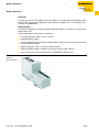

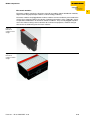
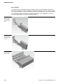
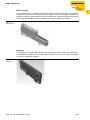
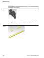
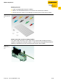


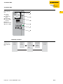
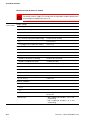

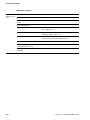


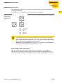


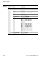
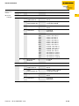

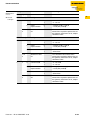
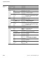


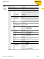


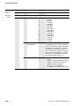
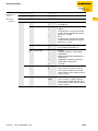

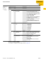
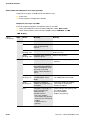
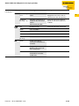


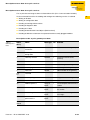
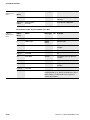

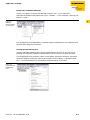

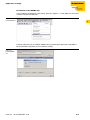
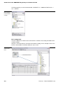

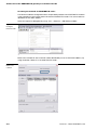
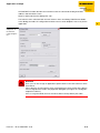
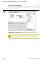
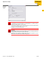


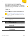

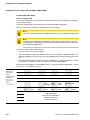

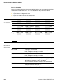
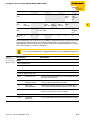


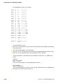
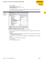
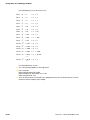
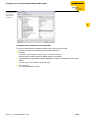
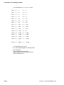


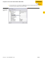
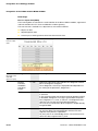
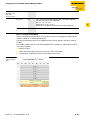


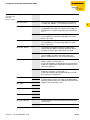
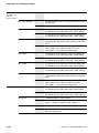


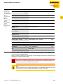


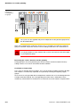
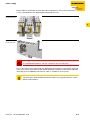


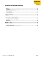

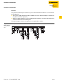

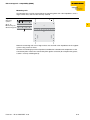

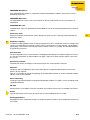


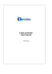


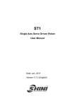


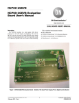
![Overview cPR67 and cPR84 [v00]](http://vs1.manualzilla.com/store/data/005648847_1-d158a5d3d4b92d14c7a3179652b88ffd-150x150.png)