1
2-9
2.3.2 Rear Panel Description
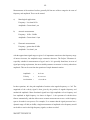
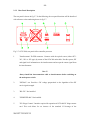
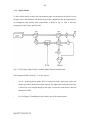
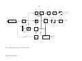
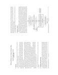
The rear panel is shown in fig. 2.7. In the following, the rear panel functions will be described
with reference to the numbering shown in fig. 2.7.
Fig. 2.7: OFV-2200, rear panel of the controller processor
1.
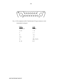
"Interferometer" D-SUB connector. Connects with the optical sensor (either OFV303, -501 or -502 type) by means of the OFA-300 main cable. Provides power, RF
and signal level information to the interferometer and accepts the return signal from
the interferometer.
Note !!!
Always install the interconnection cable to interferometer before switching on
the main power switch.
2.
"SIGNAL" out. Provides a DC voltage proportional to the logarithm of the RF
carrier signal strength.
3.
"RS-232". Not installed.
4.
"GPIB/IEEE-488". Not installed.
5.
"PC-Fringe Counter". Interface required for operation of OFV-600 PC fringe counter
card. This card allows for an increase of the standard 12 bit-range of the
_____________________
Man-OFV-2200-9602-e01