
1
Chapter 1 System Architecture ...................................................................... 1-1 1.1 Physical Architecture .............................................................................. 1.1.1 Hardware Composition of SoftX3000............................................. 1.1.2 Inter-Device Communication .......................................................... 1.1.3 System Capacity ............................................................................ 1.2 Cabinet Configuration ............................................................................. 1.2.1 Overivew of Cabinet Configuration ................................................ 1.2.2 Cabinet Configuration of Less than 100,000 Equivalent Subscribers ............................................................................................. 1.2.3 Cabinet Configuration of Less than 100,000 Equivalent Subscribers ............................................................................................. 1.3 Cabinet Features .................................................................................... 1.4 Cabinet Classification ............................................................................. 1.4.1 Overview of Cabinet Classification ................................................ 1.4.2 Integrated configuration cabinet ..................................................... 1.4.3 Service processing cabinet ............................................................ 1.4.4 MRS cabinet .................................................................................. 1.5 Cabinet Accessories ............................................................................... 1.5.1 Power Distribution Frame .............................................................. 1.5.2 Fan Box.......................................................................................... 1.5.3 Air Deflector ................................................................................... 1.5.4 LAN Switch .................................................................................... 1.6 OSTA Frame .......................................................................................... 1.6.1 Frame Structure ............................................................................. 1.6.2 Frame Classification ...................................................................... 1.6.3 Bus ................................................................................................. 1-1 1-1 1-1 1-2 1-2 1-2 1-3 1-4 1-5 1-5 1-5 1-5 1-6 1-6 1-6 1-10 1-11 1-12 1-14 1-14 1-15 1-20 Chapter 2 Introduction to Boards .................................................................. 2-1 2.1 Logical Structure .................................................................................... 2.1.1 Overview of Logical Structure ........................................................ 2.1.2 Line Interface Module .................................................................... 2.1.3 System Support Module ................................................................. 2.1.4 Signaling Processing Module......................................................... 2.1.5 Service Processing Module ........................................................... 2.1.6 Back Administration Module .......................................................... 2.2 Classification of Boards .......................................................................... 2.3 FCCU ..................................................................................................... 2.3.1 Functions ....................................................................................... 2.3.2 Technical Specifications ................................................................ 2.3.3 Indicators ....................................................................................... 2.3.4 DIP Switches and Jumpers ............................................................ 2-1 2-1 2-2 2-3 2-3 2-4 2-5 2-5 2-7 2-7 2-8 2-9 2-10 1-2 2.3.5 Configuration Calculation ............................................................... 2.4 FCSU...................................................................................................... 2.4.1 Functions ....................................................................................... 2.4.2 Technical Specifications ................................................................ 2.4.3 Indicators ....................................................................................... 2.4.4 DIP Switches and Jumpers ............................................................ 2.4.5 Configuration Calculation ............................................................... 2.5 EPII......................................................................................................... 2.5.1 Functions ....................................................................................... 2.5.2 Technical Specifications ................................................................ 2.5.3 Indicators ....................................................................................... 2.5.4 DIP Switches and Jumpers ............................................................ 2.5.5 Configuration Calculation ............................................................... 2.6 IFMI ........................................................................................................ 2.6.1 Functions ....................................................................................... 2.6.2 Technical Specifications ................................................................ 2.6.3 Indicators ....................................................................................... 2.6.4 DIP Switches and Jumpers ............................................................ 2.6.5 Configuration Calculation ............................................................... 2.7 BFII ......................................................................................................... 2.7.1 Functions ....................................................................................... 2.7.2 Technical Specifications ................................................................ 2.7.3 Indicators ....................................................................................... 2.7.4 DIP Switches and Jumpers ............................................................ 2.7.5 Configuration Calculation ............................................................... 2.8 SMUI ...................................................................................................... 2.8.1 Functions ....................................................................................... 2.8.2 Technical Specifications ................................................................ 2.8.3 Indicators ....................................................................................... 2.8.4 DIP Switches and Jumpers ............................................................ 2.8.5 Configuration Calculation ............................................................... 2.9 SIUI ........................................................................................................ 2.9.1 Functions ....................................................................................... 2.9.2 Technical Specifications ................................................................ 2.9.3 Indicators ....................................................................................... 2.9.4 DIP Switches and Jumpers ............................................................ 2.9.5 Configuration Calculation ............................................................... 2.10 MRCA ................................................................................................... 2.10.1 Functions ..................................................................................... 2.10.2 Technical Specifications .............................................................. 2.10.3 Indicators ..................................................................................... 2-11 2-11 2-11 2-13 2-13 2-14 2-15 2-15 2-15 2-16 2-16 2-17 2-18 2-18 2-18 2-18 2-19 2-20 2-20 2-21 2-21 2-21 2-21 2-22 2-22 2-22 2-22 2-23 2-23 2-25 2-25 2-25 2-25 2-25 2-26 2-26 2-27 2-27 2-27 2-27 2-28 2.10.4 DIP Switches and Jumpers .......................................................... 2.10.5 Configuration Calculation ............................................................. 2.11 MRIA .................................................................................................... 2.11.1 Functions ..................................................................................... 2.11.2 Technical Specifications .............................................................. 2.11.3 Indicators ..................................................................................... 2.11.4 DIP Switches and Jumpers .......................................................... 2.11.5 Configuration Calculation ............................................................. 2.12 BSGI ..................................................................................................... 2.12.1 Functions ..................................................................................... 2.12.2 Technical Specifications .............................................................. 2.12.3 Indicators ..................................................................................... 2.12.4 DIP Switches and Jumpers .......................................................... 2.12.5 Configuration Calculation ............................................................. 2.13 MSGI .................................................................................................... 2.13.1 Functions ..................................................................................... 2.13.2 Technical Specifications .............................................................. 2.13.3 Indicators ..................................................................................... 2.13.4 DIP Switches and Jumpers .......................................................... 2.13.5 Configuration Calculation ............................................................. 2.14 CDBI ..................................................................................................... 2.14.1 Functions ..................................................................................... 2.14.2 Technical Specifications .............................................................. 2.14.3 Indicators ..................................................................................... 2.14.4 DIP Switches and Jumpers .......................................................... 2.14.5 Configuration Calculation ............................................................. 2.15 ALUI ..................................................................................................... 2.15.1 Functions ..................................................................................... 2.15.2 Technical Specifications .............................................................. 2.15.3 Indicators ..................................................................................... 2.15.4 DIP Switches and Jumpers .......................................................... 2.15.5 Configuration Calculation ............................................................. 2.16 UPWR .................................................................................................. 2.16.1 Functions ..................................................................................... 2.16.2 Technical Specifications .............................................................. 2.16.3 Indicators ..................................................................................... 2.16.4 DIP Switches and Jumpers .......................................................... 2.17 HSCI ..................................................................................................... 2.17.1 Functions ..................................................................................... 2.17.2 Technical Specifications .............................................................. 2.17.3 Indicators ..................................................................................... 2-29 2-29 2-29 2-29 2-29 2-30 2-30 2-30 2-31 2-31 2-32 2-32 2-33 2-34 2-34 2-34 2-35 2-36 2-37 2-37 2-37 2-37 2-38 2-38 2-39 2-40 2-40 2-40 2-40 2-41 2-43 2-43 2-43 2-43 2-43 2-44 2-45 2-45 2-45 2-45 2-46 2.17.4 DIP Switches and Jumpers .......................................................... 2.17.5 Configuration Calculation ............................................................. 2.18 CKII ...................................................................................................... 2.18.1 Functions ..................................................................................... 2.18.2 Technical Specifications .............................................................. 2.18.3 Indicators ..................................................................................... 2.18.4 DIP Switches and Jumpers .......................................................... 2.18.5 Configuration Calculation ............................................................. 2-47 2-47 2-47 2-47 2-48 2-48 2-50 2-50 Chapter 3 Signaling and Protocol Processing Principles ........................... 3-1 3.1 Processing Path for Signaling over IP .................................................... 3.1.1 ISUP/INAP over MTP3/M2UA ........................................................ 3.1.2 ISUP/INAP over M3UA .................................................................. 3.1.3 MGCP/H.248 over UDP ................................................................. 3.1.4 H.323 over IP ................................................................................. 3.1.5 SIP over UDP................................................................................. 3.1.6 DSS1 over IUA ............................................................................... 3.1.7 V5.2 over V5UA ............................................................................. 3.2 Processing Path for Signaling over TDM ............................................... 3.2.1 Normal processing path ................................................................. 3.2.2 Standby processing path ............................................................... 3-1 3-1 3-3 3-5 3-8 3-13 3-16 3-18 3-20 3-20 3-21 Chapter 4 Terminal System ............................................................................ 4-1 4.1 Hardware Architecture ............................................................................ 4.2 Software Architecture ............................................................................. 4.2.1 BAM Software ................................................................................ 4.2.2 OAM Software ................................................................................ 4.2.3 Communication Gateway Software................................................ 4.3 Operation Security .................................................................................. 4.3.1 Command Group ........................................................................... 4.3.2 Workstation Management .............................................................. 4.3.3 User Account Management ........................................................... 4.3.4 Logon Time .................................................................................... 4.3.5 Locking Time .................................................................................. 4.4 Data Storage .......................................................................................... 4.4.1 Storage of BAM Data ..................................................................... 4.4.2 Storage of SoftX3000 Data ............................................................ 4.4.3 Storage of Supplementary Services .............................................. 4.5 Data Operation ....................................................................................... 4.6 Software Patch Management ................................................................. 4.6.1 Basic Concepts .............................................................................. 4-1 4-3 4-5 4-10 4-12 4-13 4-13 4-14 4-14 4-14 4-14 4-15 4-15 4-15 4-16 4-16 4-18 4-18 4.6.2 Characteristics of Software Patch .................................................. 4.6.3 Structure of Software Patch ........................................................... 4.6.4 Implementation of Software Patch ................................................. 4-19 4-20 4-21 Chapter 5 Clock System .................................................................................. 5-1 5.1 Introduction............................................................................................. 5.1.1 Features ......................................................................................... 5.1.2 Technical Specifications ................................................................ 5.2 Clock Synchronization Principle ............................................................. 5.2.1 Overall Structure of Clock System ................................................. 5.2.2 Implementation of Clock System Synchronization ......................... 5-1 5-1 5-1 5-3 5-3 5-5 Chapter 6 Charging System ............................................................................ 6-1 6.1 Basic Concepts ...................................................................................... 6.1.1 Overview of Basic Concepts .......................................................... 6.1.2 SoftX3000 Charging ....................................................................... 6.1.3 Offline billing .................................................................................. 6.1.4 Online billing .................................................................................. 6.2 Ticket Categories ................................................................................... 6.2.1 Overview of ticket categories ......................................................... 6.2.2 Detailed ticket ................................................................................ 6.2.3 Metering ticket ................................................................................ 6.2.4 Statistical ticket .............................................................................. 6.3 Logical Structure of Charging System .................................................... 6.3.1 Overview of Logical Structure of Charging System ....................... 6.3.2 Call Control Module of FCCU/FCSU .............................................. 6.3.3 Ticket Pool of FCCU/FCSU ........................................................... 6.3.4 iGWB .............................................................................................. 6.3.5 BAM ............................................................................................... 6.3.6 Billing Center .................................................................................. 6.4 Functioning Principles of Charging System ............................................ 6.4.1 Overview of Functioning Process in Charging System .................. 6.4.2 Description of Ticket Buffer in FCCU/FCSU .................................. 6.4.3 Storing Tickets in Ticket Pool......................................................... 6.4.4 Converting Meter Table Records to Tickets ................................... 6.4.5 Processing Centrex Tickets ........................................................... 6.4.6 Ticket Processing in iGWB ............................................................ 6.5 Bill Storage ............................................................................................. 6.5.1 Overview of Bill Storage ................................................................. 6.5.2 Description of Bill Storage Folders on iGWB Server ...................... 6.5.3 Storage of Original Tickets ............................................................. 6-1 6-1 6-1 6-1 6-1 6-2 6-2 6-2 6-4 6-4 6-5 6-5 6-5 6-5 6-6 6-6 6-6 6-6 6-6 6-7 6-7 6-7 6-7 6-8 6-10 6-10 6-10 6-10 6.5.4 Storage of Final Bills ...................................................................... 6-11 Chapter 7 Alarm System ................................................................................. 7-1 7.1 Structure of Alarm System ..................................................................... 7.2 Alarm Categories and Alarm Levels ....................................................... 7.2.1 Alarm Categories ........................................................................... 7.2.2 Alarm Levels .................................................................................. 7.3 Alarm Box and Alarm Console ............................................................... 7.3.1 Alarm Box ...................................................................................... 7.3.2 Alarm Console ............................................................................... 7.4 Alarm Reporting Paths ........................................................................... 7.4.1 Hardware Alarm Reporting Path .................................................... 7.4.2 Software Alarm Reporting Path ..................................................... 7-1 7-2 7-2 7-3 7-3 7-3 7-4 7-5 7-5 7-8 Appendix A Acronyms and Abbreviations .................................................... A-1 HUAWEI U-SYS SoftX3000 SoftSwitch System Technical Manual – Architecture & Principle V300R001 U-SYS SoftX3000 SoftSwitch System Technical Manual Volume Architecture & Principle Manual Version T2-010256-20040815-C-3.06 Product Version V300R001 BOM 31025856 Huawei Technologies Co., Ltd. provides customers with comprehensive technical support and service. Please feel free to contact our local office or company headquarters. Huawei Technologies Co., Ltd. Address: Administration Building, Huawei Technologies Co., Ltd., Bantian, Longgang District, Shenzhen, P. R. China Postal Code: 518129 Website: http://www.huawei.com Email: [email protected] Copyright © 2004 Huawei Technologies Co., Ltd. All Rights Reserved No part of this manual may be reproduced or transmitted in any form or by any means without prior written consent of Huawei Technologies Co., Ltd. Trademarks , HUAWEI, C&C08, EAST8000, HONET, , ViewPoint, INtess, ETS, DMC, TELLIN, InfoLink, Netkey, Quidway, SYNLOCK, Radium, M900/M1800, TELESIGHT, Quidview, Musa, Airbridge, Tellwin, Inmedia, VRP, DOPRA, iTELLIN, HUAWEI OptiX, C&C08 iNET, NETENGINE, OptiX, iSite, U-SYS, iMUSE, OpenEye, Lansway, SmartAX, infoX, TopEng are trademarks of Huawei Technologies Co., Ltd. All other trademarks mentioned in this manual are the property of their respective holders. Notice The information in this manual is subject to change without notice. Every effort has been made in the preparation of this manual to ensure accuracy of the contents, but all statements, information, and recommendations in this manual do not constitute the warranty of any kind, express or implied. About This Manual Release Notes The manual applies to U-SYS SoftX3000 SoftSwitch System V300R001. Related Manuals The related manuals are listed in the following table. Manual Content U-SYS SoftX3000 SoftSwitch System Technical Manual-System Description It provides an overall introduction to SoftX3000, including product features, applications and technical specifications. U-SYS SoftX3000 SoftSwitch System Technical Manual-Architecture & Principle It details on the hardware architecture, component interworking mechanism, and subsystems of alarm, billing, and clock in SoftX3000. U-SYS SoftX3000 SoftSwitch System Maintenance Manual-Routine Maintenance It guides the maintenance engineers to perform daily maintenance, monthly maintenance, and yearly maintenance tasks on equipment. U-SYS SoftX3000 SoftSwitch System Maintenance Manual-Emergency Maintenance It guides the maintenance engineers to perform recovery operations in the case of emergencies, such as congestion of global service, AMG, and TMG, and failure of host and BAM. U-SYS SoftX3000 SoftSwitch System Maintenance Manual-Parts Replacment It guides the maintenance engineers on how to replace hardware components such as boards, fan frame, LAN Switch, and hard disk. U-SYS SoftX3000 SoftSwitch System Hardware Installation Manual It details the installation procedure of SoftX3000 hardware components, and matters needing attention during the installation process. U-SYS SoftX3000 SoftSwitch System Software Installation Manual It covers the detailed procedure of installing SoftX3000 software, including BAM server, emergency workstation and client, focusing on the key points that might cause installation failure. U-SYS SoftX3000 SoftSwitch System Operation Manual-Traffic Measurement It guides the engineers how to perform traffic measurement operations and how to analyze traffic measurement results. U-SYS SoftX3000 SoftSwitch System Operation Manual- Configuration Guide It guides the engineers how to configure various data in SoftX3000, including configuration steps, preparations, database table referencing relationships, and command parameters. U-SYS SoftX3000 SoftSwitch System Operation Manual-Configuration Example It guides the engineers how to configure various data in SoftX3000, including networking example, configuration script, key parameters and debugging guidance. U-SYS SoftX3000 SoftSwitch System Operation Manual-Service Application It covers the voice services, IP Centrex services, multi-media services, IN services and value added services supported by SoftX3000, focusing on the meaning, operations, example and points for attention of various services. U-SYS iGateway Bill User Manual It elaborates on the functioning principle of the iGateway Bill. Also, it teaches you on how to install, maintain, and operate the product. Organization This manual introduces the hardware architecture, component interworking mechanism, and subsystems of alarm, billing, and clock in SoftX3000. There are ten chapters in the manual. Chapter 1 System Architecture profiles hardware architecture of SoftX3000 as z well as the important components. Chapter 2 Introduction to Boards details the functions and features of all boards z used in SoftX3000. Chapter 3 Signaling and Protocol Processing Principles presents the z signaling and protocols processing paths applied in SoftX3000. Chapter z 4 Terminal System details interoperation maintenance and management between terminal components such as BAM, iGWB, emergency workstation, and client. Chapter 5 Clock System provides more information about the features, z specifications, and synchronization principle of the clock system in SoftX3000. Chapter 6 Charging System focuses on the charging and billing process and z mechanism in SoftX3000.. Chapter 7 Alarm System details on alarm system architecture, the functions and z features of alarm box and alarm console, and alarm reporting path. Appendix A Acronyms and Abbreviations collects the definitions of terms and z acronyms that are used in this manual. Intended Readers The manual is intended for the following readers: z NGN network planning experts z NGN network administrators z NGN system engineers Conventions The manual uses the following conventions: I. General conventions Convention Description Arial Normal paragraphs are in Arial. Arial Narrow Warnings, Cautions, Notes and Tips are in Arial Narrow. Boldface Headings are in Boldface. Convention Courier New Description Terminal Display is in Courier New. II. Symbols Eye-catching symbols are also used in the manual to highlight the points worthy of special attention during the operation. They are defined as follows: Caution Means reader be extremely careful during the operation. Note Means a complementary description.. Technical Manual - Architecture & Principle U-SYS SoftX3000 SoftSwitch System Table of Contents Table of Contents Chapter 1 System Architecture.................................................................................................... 1-1 1.1 Physical Architecture ......................................................................................................... 1-1 1.1.1 Hardware Composition of SoftX3000...................................................................... 1-1 1.1.2 Inter-Device Communication................................................................................... 1-1 1.1.3 System Capacity ..................................................................................................... 1-2 1.2 Cabinet Configuration ........................................................................................................ 1-2 1.2.1 Overivew of Cabinet Configuration ......................................................................... 1-2 1.2.2 Cabinet Configuration of Less than 100,000 Equivalent Subscribers..................... 1-2 1.2.3 Cabinet Configuration of Less than 100,000 Equivalent Subscribers..................... 1-3 1.3 Cabinet Features ............................................................................................................... 1-4 1.4 Cabinet Classification ........................................................................................................ 1-5 1.4.1 Overview of Cabinet Classification.......................................................................... 1-5 1.4.2 Integrated configuration cabinet.............................................................................. 1-5 1.4.3 Service processing cabinet ..................................................................................... 1-5 1.4.4 MRS cabinet............................................................................................................ 1-6 1.5 Cabinet Accessories .......................................................................................................... 1-6 1.5.1 Power Distribution Frame........................................................................................ 1-6 1.5.2 Fan Box ................................................................................................................. 1-10 1.5.3 Air Deflector........................................................................................................... 1-11 1.5.4 LAN Switch............................................................................................................ 1-12 1.6 OSTA Frame.................................................................................................................... 1-14 1.6.1 Frame Structure .................................................................................................... 1-14 1.6.2 Frame Classification.............................................................................................. 1-15 1.6.3 Bus ........................................................................................................................ 1-20 Chapter 2 Introduction to Boards ................................................................................................ 2-1 2.1 Logical Structure ................................................................................................................ 2-1 2.1.1 Overview of Logical Structure ................................................................................. 2-1 2.1.2 Line Interface Module.............................................................................................. 2-2 2.1.3 System Support Module.......................................................................................... 2-3 2.1.4 Signaling Processing Module.................................................................................. 2-3 2.1.5 Service Processing Module..................................................................................... 2-4 2.1.6 Back Administration Module.................................................................................... 2-5 2.2 Classification of Boards ..................................................................................................... 2-5 2.3 FCCU ................................................................................................................................. 2-7 2.3.1 Functions................................................................................................................. 2-7 2.3.2 Technical Specifications.......................................................................................... 2-8 2.3.3 Indicators................................................................................................................. 2-9 i Technical Manual - Architecture & Principle U-SYS SoftX3000 SoftSwitch System Table of Contents 2.3.4 DIP Switches and Jumpers ................................................................................... 2-10 2.3.5 Configuration Calculation ...................................................................................... 2-11 2.4 FCSU ............................................................................................................................... 2-11 2.4.1 Functions............................................................................................................... 2-11 2.4.2 Technical Specifications........................................................................................ 2-13 2.4.3 Indicators............................................................................................................... 2-13 2.4.4 DIP Switches and Jumpers ................................................................................... 2-14 2.4.5 Configuration Calculation ...................................................................................... 2-15 2.5 EPII .................................................................................................................................. 2-15 2.5.1 Functions............................................................................................................... 2-15 2.5.2 Technical Specifications........................................................................................ 2-16 2.5.3 Indicators............................................................................................................... 2-16 2.5.4 DIP Switches and Jumpers ................................................................................... 2-17 2.5.5 Configuration Calculation ...................................................................................... 2-18 2.6 IFMI.................................................................................................................................. 2-18 2.6.1 Functions............................................................................................................... 2-18 2.6.2 Technical Specifications........................................................................................ 2-18 2.6.3 Indicators............................................................................................................... 2-19 2.6.4 DIP Switches and Jumpers ................................................................................... 2-20 2.6.5 Configuration Calculation ...................................................................................... 2-20 2.7 BFII .................................................................................................................................. 2-21 2.7.1 Functions............................................................................................................... 2-21 2.7.2 Technical Specifications........................................................................................ 2-21 2.7.3 Indicators............................................................................................................... 2-21 2.7.4 DIP Switches and Jumpers ................................................................................... 2-22 2.7.5 Configuration Calculation ...................................................................................... 2-22 2.8 SMUI ................................................................................................................................ 2-22 2.8.1 Functions............................................................................................................... 2-22 2.8.2 Technical Specifications........................................................................................ 2-23 2.8.3 Indicators............................................................................................................... 2-23 2.8.4 DIP Switches and Jumpers ................................................................................... 2-25 2.8.5 Configuration Calculation ...................................................................................... 2-25 2.9 SIUI .................................................................................................................................. 2-25 2.9.1 Functions............................................................................................................... 2-25 2.9.2 Technical Specifications........................................................................................ 2-25 2.9.3 Indicators............................................................................................................... 2-26 2.9.4 DIP Switches and Jumpers ................................................................................... 2-26 2.9.5 Configuration Calculation ...................................................................................... 2-27 2.10 MRCA ............................................................................................................................ 2-27 2.10.1 Functions............................................................................................................. 2-27 2.10.2 Technical Specifications...................................................................................... 2-27 2.10.3 Indicators............................................................................................................. 2-28 ii Technical Manual - Architecture & Principle U-SYS SoftX3000 SoftSwitch System Table of Contents 2.10.4 DIP Switches and Jumpers ................................................................................. 2-29 2.10.5 Configuration Calculation .................................................................................... 2-29 2.11 MRIA .............................................................................................................................. 2-29 2.11.1 Functions............................................................................................................. 2-29 2.11.2 Technical Specifications...................................................................................... 2-29 2.11.3 Indicators............................................................................................................. 2-30 2.11.4 DIP Switches and Jumpers ................................................................................. 2-30 2.11.5 Configuration Calculation .................................................................................... 2-30 2.12 BSGI .............................................................................................................................. 2-31 2.12.1 Functions............................................................................................................. 2-31 2.12.2 Technical Specifications...................................................................................... 2-32 2.12.3 Indicators............................................................................................................. 2-32 2.12.4 DIP Switches and Jumpers ................................................................................. 2-33 2.12.5 Configuration Calculation .................................................................................... 2-34 2.13 MSGI.............................................................................................................................. 2-34 2.13.1 Functions............................................................................................................. 2-34 2.13.2 Technical Specifications...................................................................................... 2-35 2.13.3 Indicators............................................................................................................. 2-36 2.13.4 DIP Switches and Jumpers ................................................................................. 2-37 2.13.5 Configuration Calculation .................................................................................... 2-37 2.14 CDBI .............................................................................................................................. 2-37 2.14.1 Functions............................................................................................................. 2-37 2.14.2 Technical Specifications...................................................................................... 2-38 2.14.3 Indicators............................................................................................................. 2-38 2.14.4 DIP Switches and Jumpers ................................................................................. 2-39 2.14.5 Configuration Calculation .................................................................................... 2-40 2.15 ALUI ............................................................................................................................... 2-40 2.15.1 Functions............................................................................................................. 2-40 2.15.2 Technical Specifications...................................................................................... 2-40 2.15.3 Indicators............................................................................................................. 2-41 2.15.4 DIP Switches and Jumpers ................................................................................. 2-43 2.15.5 Configuration Calculation .................................................................................... 2-43 2.16 UPWR ............................................................................................................................ 2-43 2.16.1 Functions............................................................................................................. 2-43 2.16.2 Technical Specifications...................................................................................... 2-43 2.16.3 Indicators............................................................................................................. 2-44 2.16.4 DIP Switches and Jumpers ................................................................................. 2-45 2.17 HSCI .............................................................................................................................. 2-45 2.17.1 Functions............................................................................................................. 2-45 2.17.2 Technical Specifications...................................................................................... 2-45 2.17.3 Indicators............................................................................................................. 2-46 2.17.4 DIP Switches and Jumpers ................................................................................. 2-47 iii Technical Manual - Architecture & Principle U-SYS SoftX3000 SoftSwitch System Table of Contents 2.17.5 Configuration Calculation .................................................................................... 2-47 2.18 CKII ................................................................................................................................ 2-47 2.18.1 Functions............................................................................................................. 2-47 2.18.2 Technical Specifications...................................................................................... 2-48 2.18.3 Indicators............................................................................................................. 2-48 2.18.4 DIP Switches and Jumpers ................................................................................. 2-50 2.18.5 Configuration Calculation .................................................................................... 2-50 Chapter 3 Signaling and Protocol Processing Principles......................................................... 3-1 3.1 Processing Path for Signaling over IP ............................................................................... 3-1 3.1.1 ISUP/INAP over MTP3/M2UA................................................................................. 3-1 3.1.2 ISUP/INAP over M3UA ........................................................................................... 3-3 3.1.3 MGCP/H.248 over UDP .......................................................................................... 3-5 3.1.4 H.323 over IP .......................................................................................................... 3-8 3.1.5 SIP over UDP ........................................................................................................ 3-13 3.1.6 DSS1 over IUA ...................................................................................................... 3-16 3.1.7 V5.2 over V5UA..................................................................................................... 3-18 3.2 Processing Path for Signaling over TDM......................................................................... 3-20 3.2.1 Normal processing path ........................................................................................ 3-20 3.2.2 Standby processing path....................................................................................... 3-21 Chapter 4 Terminal System .......................................................................................................... 4-1 4.1 Hardware Architecture ....................................................................................................... 4-1 4.2 Software Architecture ........................................................................................................ 4-3 4.2.1 BAM Software ......................................................................................................... 4-5 4.2.2 OAM Software ....................................................................................................... 4-10 4.2.3 Communication Gateway Software....................................................................... 4-12 4.3 Operation Security ........................................................................................................... 4-13 4.3.1 Command Group................................................................................................... 4-13 4.3.2 Workstation Management ..................................................................................... 4-14 4.3.3 User Account Management................................................................................... 4-14 4.3.4 Logon Time ........................................................................................................... 4-14 4.3.5 Locking Time ......................................................................................................... 4-14 4.4 Data Storage.................................................................................................................... 4-15 4.4.1 Storage of BAM Data ............................................................................................ 4-15 4.4.2 Storage of SoftX3000 Data ................................................................................... 4-15 4.4.3 Storage of Supplementary Services...................................................................... 4-16 4.5 Data Operation................................................................................................................. 4-16 4.6 Software Patch Management .......................................................................................... 4-18 4.6.1 Basic Concepts ..................................................................................................... 4-18 4.6.2 Characteristics of Software Patch ......................................................................... 4-19 4.6.3 Structure of Software Patch .................................................................................. 4-20 4.6.4 Implementation of Software Patch ........................................................................ 4-21 iv Technical Manual - Architecture & Principle U-SYS SoftX3000 SoftSwitch System Table of Contents Chapter 5 Clock System ............................................................................................................... 5-1 5.1 Introduction ........................................................................................................................ 5-1 5.1.1 Features .................................................................................................................. 5-1 5.1.2 Technical Specifications.......................................................................................... 5-1 5.2 Clock Synchronization Principle ........................................................................................ 5-3 5.2.1 Overall Structure of Clock System .......................................................................... 5-3 5.2.2 Implementation of Clock System Synchronization.................................................. 5-5 Chapter 6 Charging System ......................................................................................................... 6-1 6.1 Basic Concepts .................................................................................................................. 6-1 6.1.1 Overview of Basic Concepts ................................................................................... 6-1 6.1.2 SoftX3000 Charging................................................................................................ 6-1 6.1.3 Offline billing............................................................................................................ 6-1 6.1.4 Online billing............................................................................................................ 6-1 6.2 Ticket Categories ............................................................................................................... 6-2 6.2.1 Overview of ticket categories .................................................................................. 6-2 6.2.2 Detailed ticket.......................................................................................................... 6-2 6.2.3 Metering ticket ......................................................................................................... 6-4 6.2.4 Statistical ticket........................................................................................................ 6-4 6.3 Logical Structure of Charging System ............................................................................... 6-5 6.3.1 Overview of Logical Structure of Charging System ................................................ 6-5 6.3.2 Call Control Module of FCCU/FCSU....................................................................... 6-5 6.3.3 Ticket Pool of FCCU/FCSU..................................................................................... 6-5 6.3.4 iGWB ....................................................................................................................... 6-6 6.3.5 BAM......................................................................................................................... 6-6 6.3.6 Billing Center ........................................................................................................... 6-6 6.4 Functioning Principles of Charging System....................................................................... 6-6 6.4.1 Overview of Functioning Process in Charging System ........................................... 6-6 6.4.2 Description of Ticket Buffer in FCCU/FCSU ........................................................... 6-7 6.4.3 Storing Tickets in Ticket Pool.................................................................................. 6-7 6.4.4 Converting Meter Table Records to Tickets............................................................ 6-7 6.4.5 Processing Centrex Tickets .................................................................................... 6-7 6.4.6 Ticket Processing in iGWB...................................................................................... 6-8 6.5 Bill Storage....................................................................................................................... 6-10 6.5.1 Overview of Bill Storage........................................................................................ 6-10 6.5.2 Description of Bill Storage Folders on iGWB Server............................................. 6-10 6.5.3 Storage of Original Tickets.................................................................................... 6-10 6.5.4 Storage of Final Bills ............................................................................................. 6-11 Chapter 7 Alarm System............................................................................................................... 7-1 7.1 Structure of Alarm System................................................................................................. 7-1 7.2 Alarm Categories and Alarm Levels .................................................................................. 7-2 7.2.1 Alarm Categories..................................................................................................... 7-2 7.2.2 Alarm Levels............................................................................................................ 7-3 v Technical Manual - Architecture & Principle U-SYS SoftX3000 SoftSwitch System Table of Contents 7.3 Alarm Box and Alarm Console........................................................................................... 7-3 7.3.1 Alarm Box................................................................................................................ 7-3 7.3.2 Alarm Console......................................................................................................... 7-4 7.4 Alarm Reporting Paths....................................................................................................... 7-5 7.4.1 Hardware Alarm Reporting Path ............................................................................. 7-5 7.4.2 Software Alarm Reporting Path............................................................................... 7-8 Appendix A Acronyms and Abbreviations .................................................................................A-1 vi Technical Manual - Architecture & Principle U-SYS SoftX3000 SoftSwitch System Chapter 1 System Architecture Chapter 1 System Architecture 1.1 Physical Architecture 1.1.1 Hardware Composition of SoftX3000 U-SYS SoftX3000 SoftSwitch System (hereinafter referred to as SoftX3000) is composed of Open Standards Telecom Architecture Platform (OSTA) frame, Back Administration Module (BAM), and iGateway Bill (the billing gateway, hereinafter referred to as iGWB) physically.OSTA frames contained in N68-22 cabinets construct the host of SoftX3000, implementing service processing and resource management functions. The BAM and the iGWB constitute the background of SoftX3000, which is responsible for operation, maintenance and bill management functions. The physical structure of SoftX3000 is illustrated in Figure 1-1. FE FE Frame 0# To the billing center FE Standby iGWB Frame 1# LAN Switch in plane 1 GE To the billing center Active iGWB LAN Switch in plane 0 BAM Frame 2# Hub Emergency WS Frame 17# WS Host FE: Fast Ethernet To the network Management center WS WS Background GE: Gigabit Ethernet WS: Workstation Figure 1-1 Physical structure of SoftX3000 1.1.2 Inter-Device Communication The frames communicate with each other through two LAN Switches (LAN Switch in the plane 0 and LAN Switch in the plane 1). Each frame is connected to both LAN Switches through network cables respectively. 1-1 Technical Manual - Architecture & Principle U-SYS SoftX3000 SoftSwitch System Chapter 1 System Architecture The communication between the frames and the BAM/iGWB is achieved through the two LAN Switches. The BAM and the iGWB are connected to both LAN Switches through network cables respectively. The BAM and the iGWB are connected to a hub using a network cable respectively. The workstations communicate with the BAM and the iGWB over TCP/IP in the client/server model. The BAM periodically backs up the data to the emergency workstation. Once the BAM becomes faulty, the emergency workstation takes the responsibility of the BAM as long as its network cables are connected to both LAN Switches in the planes 0 and 1 respectively. 1.1.3 System Capacity In an actual deployment, the capacity of the system depends on the quantity of configured OSTA frames, which fully meets the requirement of smooth expansion. At maximum, 18 OSTA frames can be configured. 1.2 Cabinet Configuration 1.2.1 Overivew of Cabinet Configuration SoftX3000 provides two modes of cabinet configuration as follows: z Cabinet configuration of less than 100,000 equivalent subscribers z Cabinet configuration of more than 100,000 equivalent subscribers 1.2.2 Cabinet Configuration of Less than 100,000 Equivalent Subscribers Standard configuration + built-in media resource board + BAM + iGWB server: applicable to a capacity which is less than 100,000 equivalent subscribers. Figure 1-2 shows the cabinet configuration of this mode. 1-2 Technical Manual - Architecture & Principle U-SYS SoftX3000 SoftSwitch System Chapter 1 System Architecture Integrated configuration cabinet Service processing cabinet Pow er distribution frame Pow er distribution frame Blank filler panel (3U) Media resource frame (01) (9U) Blank filler panel (3U) Blank filler panel (3U) Air deflector (2U) Blank filler panel (2U) Blank filler panel (3U) Basic frame (00) (9U) Blank filler panel (3U) Blank filler panel (3U) Air deflector (2U) LCD + KVM (1U) LAN Sw itch 1 (1U) Cabling trough (1U) LAN Sw itch 0 (1U) Cabling trough (1U) Hard disk array (3U) Blank filler panel (1U) BAM (1U) Blank filler panel (2U) Blank filler panel (3U) Blank filler panel (3U) Blank filler panel (3U) Blank filler panel (2U) Blank filler panel (1U) iGWB (standby) (1U) Blank filler panel (1U) Expansion frame (02) (9U) iGWB (active) (1U) Blank filler panel (3U) Blank filler panel (2U) Blank filler panel (2U) LCD: Liquid Crystal Display KVM: Keyboard/Video/Mouse Figure 1-2 Cabinet configuration with a capacity less than 100,000 equivalent subscribers Note: On the integrated configuration cabinet, the lower iGWB is the active device and the upper iGWB works in the standby mode. 1.2.3 Cabinet Configuration of Less than 100,000 Equivalent Subscribers Standard configuration + separate Media Resource Server (MRS) + BAM + iGWB server: applicable to a capacity which is greater than 100,000 equivalent subscribers. Figure 1-3 shows the cabinet configuration of this mode. 1-3 Technical Manual - Architecture & Principle U-SYS SoftX3000 SoftSwitch System MRS cabinet Pow er distribution frame Chapter 1 System Architecture Integrated configuration cabinet Service processing cabinet 1 Service processing cabinet 2 Service processing cabinet 3 Pow er distribution frame Pow er distribution frame Pow er distribution frame Pow er distribution frame Expansion frame (01) (9U) Basic frame 1 (05) (9U) Expansion frame (09) (9U) Expansion frame (13) (9U) Air deflector (2U) Air deflector (2U) Air deflector (2U) Air deflector (2U) Basic frame 0 (00) (9U) Expansion frame (04) (9U) Expansion frame (08) (9U) Expansion frame (12) (9U) Air deflector (2U) Air deflector (2U) Air deflector (2U) Air deflector (2U) Expansion frame (03) (9U) Expansion frame (07) (9U) Expansion frame (11) (9U) Air deflector (2U) Air deflector (2U) Air deflector (2U) Expansion frame (02) (9U) Expansion frame (06) (9U) Expansion frame (10) (9U) Blank filler panel (2U) Blank filler panel (2U) Blank filler panel (2U) Blank filler panel (3U) Blank filler panel (3U) Blank filler panel (3U) Blank filler panel (2U) MRS6000 frame (13U) Blank filler panel (3U) Blank filler panel (2U) Blank filler panel (2U) Blank filler panel (3U) LCD + KVM (1U) LAN Sw itch 1 (1U) Cabling trough (1U) LAN Sw itch 0 (1U) Cabling trough (1U) Hard disk array (3U) Blank filler panel (1U) BAM (1U) Blank filler panel (1U) iGWB (standby) (1U) Blank filler panel (1U) Blank filler panel (3U) iGWB (active) (1U) Blank filler panel (3U) Blank filler panel (3U) Blank filler panel (2U) Blank filler panel (2U) Figure 1-3 Cabinet configuration with a capacity greater than 100,000 equivalent subscribers 1.3 Cabinet Features SoftX3000 adopts N68-22 cabinets. One cabinet can accommodate a maximum of 4 standard 19-inch frames. N68-22 cabinet is assembled with electrolytic zinc-coated cold-rolled steel sheet and screws, featuring light weight, simple structure and high versatility. The fire-proof materials conform to the Underwriter Laboratory (UL) standards. The cabinet surface is NC purple-gray and NC silver-gray, and the rack is NC purple-gray. As the front/back doors of the cabinet adopt double-door mode, the installation space is thus saved and operations to the equipment are facilitated. The side panels are just hung on the cabinet, thus facilitating installation. The front and back doors and the bottom plate have minute air vents and are configured with air filters inside. The cabinet adopts front-in, back-out and bottom-to-top ventilation mode so that it has excellent heat dissipation and dust-proof functions. Dimensions of a cabinet: 2200 mm (height) x 600 mm (width) x 800 mm (depth) Height of available space of a cabinet: 46 U (1 U = 44.45 mm) 1-4 Technical Manual - Architecture & Principle U-SYS SoftX3000 SoftSwitch System Chapter 1 System Architecture Weight: 130 kg as an empty cabinet, or 400 kg with full configuration 1.4 Cabinet Classification 1.4.1 Overview of Cabinet Classification SoftX3000 cabinets fall into the following types according to cabinet components and actual configurations. z Integrated configuration cabinet: Mandatory. This cabinet must be configured to provide external interfaces, such as IP, clock signals, and TDM, to outside and bridge SoftX3000 and BAM for communication, charging, and storing purposes. This cabinet is able to provide complete service processing functions at the minimum configuration. z Service processing cabinet: Optional. This type of cabinet may be configured. A service processing cabinet is composed of power distribution frame, expansion frame, media resource frame, and air deflector. z Media Resource Server (MRS) cabinet: Optional. An MRS cabinet is composed of power distribution frame and MRS frame. This cabinet is required when you choose to configure a physically separate MRS. 1.4.2 Integrated configuration cabinet I. Configuration guidance In an integrated configuration cabinet, iGWB, hard disk array, BAM, LAN Switch, LCD/KVM, air deflector, basic frame, and power distribution frame must be configured. Other components are optional. If you choose a separate MRS, an expansion frame must be configured at the near top of the integrated configuration cabinet. Otherwise, a media resource frame needs to be configured there. II. Configuration notes If neither an expansion frame 01 nor a media resource frame 01 is configured at the near top of the integrated configuration cabinet, then standard blank filler panel must be used to cover there. The media resource frame accommodates MRCA and MRIA only. 1.4.3 Service processing cabinet I. Configuration guidance One service processing cabinet accommodates a maximum of 4 OSTA frames. The functions of a service processing cabinet are subject to the boards inserted in it. 1-5 Technical Manual - Architecture & Principle U-SYS SoftX3000 SoftSwitch System Chapter 1 System Architecture Where functional frames are installed in different service processing cabinets depends on cabinet configuration modes. Refer to 1.2 Cabinet Configuration. Frames are installed upwards from the bottom of a cabinet, with expansion convenience taken into consideration. II. Configuration notes If less than 4 frames are installed in a service processing cabinet, empty holes must be covered with blank filler panels. 1.4.4 MRS cabinet When the number of equivalent subscribers is greater than 100,000, it is required to configure an MRS cabinet. The MRS cabinet contains a power distribution frame and an MRS6000 frame. The position and number of the installed frames are fixed and invariable. 1.5 Cabinet Accessories 1.5.1 Power Distribution Frame I. Overview of Power Distribution Frame The power distribution frame (PDF) is installed at the top of an N68-22 cabinet, which complies with the International Electrotechnical Commission 297 standard. Its height is 2 U, and its depth is 420 mm. Two channels of -48 V power supply are diverted into a power distribution frame where lightning protection and overcurrent protection operations are performed and finally 6 groups of -48 V power supply are distributed to the functional frames in the cabinet. In addition, the power distribution frame keeps monitoring the voltage of lead-in power and the state of distributed power. When necessary, an audio alarm will be generated. The power consumption of a power distribution frame is 20 W. II. Appearance z Front view The front view of a power distribution frame is shown in Figure 1-4. 1-6 Technical Manual - Architecture & Principle U-SYS SoftX3000 SoftSwitch System Chapter 1 System Architecture (1) Running indicator (4)~(6) -48V1 outlet control switches (2) Alarm indicator (7)~(9) -48V2 outlet control switches (3) Sound/mute switch (10) Front panel of lightning protection unit Figure 1-4 Front view of a power distribution frame There are two indicators on the front panel of the power distribution frame. Table 1-1shows the meanings of the indicators. Table 1-1 Meanings of the indicators on the front panel of the PDF Indicator RUN ALM Full name Running indicator Alarm indicator Color Green Red State Meaning of state Blinking once every second There are power inputs, and the PDF is working well. Off There is no power input, or the power distribution frame fails. On or blinking fast Alarming, indicating faults are encountered in the power distribution frame. Off No fault is encountered. The sound/mute switch on the front panel is used to select whether or not to produce alarm sound pertaining to the power distribution frame. If the switch is ON, alarm sound will be produced whenever a fault is encountered in the power distribution frame; if the switch is OFF, alarm sound will be muted when a fault is encountered in the power distribution frame. III. Back view There are input and output terminal blocks and monitor ports on the rear panel of a power distribution frame, as shown in Figure 1-5. 1-7 Technical Manual - Architecture & Principle U-SYS SoftX3000 SoftSwitch System Chapter 1 System Architecture (1) (2) (3) (1) Power input terminal block (2) Power output terminal block (3) External ports from monitor board Figure 1-5 Back view of a power distribution frame The PDF receives two –48 V power inputs and provides six independent –48 V power outputs. The connection positions of –48V power cables and BGND are marked on the power input and output terminal busbar. A power distribution frame externally provides one RS485 serial port, five channels of external Boolean value detection interfaces, one cascade inlet and one cascade outlet for cabinet indicator alarm, one cabinet indicator interface, one alarm row indicator interface, and one alarm column indicator interface. Monitor cable of the power distribution frame is connected to the RS485 serial port marked with COM1 and COM2. IV. Power distribution to cabinet components The six channels of power supply from a power distribution frame are distributed to the components inside the cabinet, as shown in Figure 1-6 and Figure 1-7. 1-8 Technical Manual - Architecture & Principle U-SYS SoftX3000 SoftSwitch System Chapter 1 System Architecture Power distribution frame SW1 SW2 1 SW3 SW4 3 4 2 SW5 Power distribution frame SW6 SW1 SW2 SW3 SW4 SW5 6 1 2 3 4 5 5 CN16IP frame 6 4 Basic frame 0 CN16IP frame 5 KVM/LCD LAN Switch 0 LAN Switch 1 6 1 5 CN16IP frame SW6 2 2 3 4 2 CN16IP frame 3 4 1 6 3 4 1 3 2 4 Hard disk array BAM iGWB 0 iGWB 1 3 5 CN16IP frame Integrated configuration cabinet 6 Service processing cabinet Figure 1-6 Switch allocation of a power distribution frame in an integrated configuration cabinet and in a service processing cabinet Power distribution frame SW1 SW2 SW3 SW4 SW5 1 2 3 4 5 SW6 6 Blank filler panel MRS frame 1 2 Blank filler panel Blank filler panel MRS cabinet Figure 1-7 Switch allocation of a power distribution frame in an MRS cabinet 1-9 Technical Manual - Architecture & Principle U-SYS SoftX3000 SoftSwitch System Chapter 1 System Architecture 1.5.2 Fan Box I. Overview of Fan Box A fan box is installed at the bottom of each service frame. It is designed for heat dissipation purposes. II. Appearance of Fan Box The appearance of a fan box is shown in Figure 1-8. (1) Fan box body (4) M3x8 pan head screw assembly (2) Fan (5) Fan box monitor board (3) M3x25 pan head screw assembly Figure 1-8 Fan box structure Each fan box accommodates six fans. The diameter of each fan is 119 mm, and the thickness of each fan is 32 mm. III. Front View The front view of a fan box is shown in Figure 1-9. (1) Captive screw (2) Fan state indicator Figure 1-9 Front view of a fan box 1-10 Technical Manual - Architecture & Principle U-SYS SoftX3000 SoftSwitch System Chapter 1 System Architecture If all the fans work well, the state indicator turns green and blinks at a frequency of 1 Hz. Otherwise, the fans may work abnormally, the communication monitor board may be faulty, or the power supply for the fan box may fail. IV. Rear View Figure 1-10 shows the rear view of a fan box. (1) RS485 port for power input (connected with fan box monitor cable) Figure 1-10 Rear view of a fan box V. Product Performance A speed adjustment technique is used in the fans. On the premise of normal heat dissipation and reliable running, the rotate speed of the fans can be controlled. The fans are hot-swappable. The running state of the fans can be known by observing the indicators The fan box can be maintained through a remote network management terminal. VI. Technical Specifications Input voltage: -58 V ~ -40 V Maximum power consumption of a fan box: 105 W Communication rate through RS485: 9.6 kbit/s 1.5.3 Air Deflector As show in Figure 1-11, an air deflector is used to smooth and divert air to a different direction and separate heat dissipation channels of the frames, so that air can be taken in from the front and exhausted to the rear. Moreover, the pressure consumption of the air can be minimized through an air deflector. An air deflector is 2 U high and 373.3 mm deep. 1-11 Technical Manual - Architecture & Principle U-SYS SoftX3000 SoftSwitch System Chapter 1 System Architecture Power distribution frame Service frame Fan box Air deflector Service frame Front of a cabinet Rear of a cabinet Fan box Air deflector Service frame Fan box Figure 1-11 Heat dissipation channel inside a cabinet (side view) Air deflector is installed at a fixed position of a cabinet. An air deflector is 2 U in height. There are a number of ventilation holes on its plastic front panel, as shown in Figure 1-12. Figure 1-12 Air deflector structure 1.5.4 LAN Switch I. Functions In an integrated configuration cabinet, Quidway S3526 LAN Switch of Huawei interconnects frames and servers, achieves dual planes for inter-component communication channels, and provides inter-component communication and active/standby configuration functions. 1-12 Technical Manual - Architecture & Principle U-SYS SoftX3000 SoftSwitch System Chapter 1 System Architecture Caution: LAN Switch in an integrated configuration cabinet can be only connected with the HSCI, the iGWB server network port, the emergency workstation, and the BAM. II. Technical Specifications Category Parameter Specification MAC address 16-K, 64K MAC and 16-K IP address table Buffer size 6 MB Transfer mode Store-and-forward Network and flow control L2/L3 switching Flow control Remark Supporting IEEE 802.3x defined flow control (full duplex) Back pressure flow control (semi duplex) VLAN Functions 802.1Q 4-K VLAN Spanning Tree Supported Category service Supported Priority level IEEE 802.1p Supported standards IEEE 802.1d, IEEE 802.1p, IEEE802.1Q, IEEE 802.3u, IEEE 802.3x, and Huawei Group Management Protocol (HGMP) 10/100BASE-TX: 100 meters for category 3/4/5 shielded/unshielded twisted pair Maximum length of cable 100BASE-FX: 2000 meters for 62.5/125m multi-mode optical fiber 15,000 meters for 10m single-mode optical fiber Security standards UL 1950/CSA22.2-950; IEC 950, EN60950 (CE), AS/NZ 3260 Electromagnetic compatibility FCC Part 15, Subpart J, Class A; EN55022(CISPR:1993), Class A; VCCI Class A ITE; C-tick; IEC 1000-4-2; IEC 1000-4-3; IEC 1000-4-4; IEC 1000-4-5 10/100BASE-TX: RJ-45 Interface type 100BASE-FX: SC Console management interface: RJ-45 Functions Weight 4 kg 1-13 Technical Manual - Architecture & Principle U-SYS SoftX3000 SoftSwitch System Category Interfaces Chapter 1 System Architecture Parameter Specification 10/100 Mbit/s adaptive network port 24 100BASEinterface 2 FX Console interface Power consumptio n Remark 1 = 30 W 1.6 OSTA Frame 1.6.1 Frame Structure The Huawei OSTA platform is adopted in SoftX3000 as the hardware platform. The OSTA platform has both the shared resource bus and the Ethernet bus, and enables SoftX3000 to be in good universality and high reliability. This is applicable to the exchange and transfer of variable-length data packets of the SoftSwitch equipment. The OSTA platform is structured in a standard frame which is 19 inches wide and 9U high. Front boards and back boards are installed as shown in Figure 1-13. Interface boards Ethernet communication boards Interface boards Power boards Back boards Backplane Front boards Service boards System management boards Service boards Alarm board Power boards Figure 1-13 Overall structure of the OSTA frame In the OSTA frame, front boards include service boards, system management boards and alarm boards; back boards are interface boards and Ethernet communication boards. Power boards can be installed either at the front or at the back. That front-back installation mode separates the functions of the front boards from the back boards, which simplifies the board design and orients the board functions towards unification. Therefore, the complexity of the hardware can be minimized and the reliability of the system can be improved. In addition, the board installation mode also 1-14 Technical Manual - Architecture & Principle U-SYS SoftX3000 SoftSwitch System Chapter 1 System Architecture widens the universality of the boards and enhances the flexibility of the system configuration. In SoftX3000, all frames can be used universally. Each frame is designed in the width of 21 standard board slots. System Management Units (SMUIs), System Interface Units (SIUIs), Hot-Swap and Control Units (HSCIs), Alarm Units (ALMIs) and Universal Power Modules (UPWRs) (occupying the width of 2 standard board slots) must be configured in the fixed slots of the frame, occupying the width of 9 standard board slots. The remaining 12 slots are used for service boards and interface boards. Service frame has the following characteristics. z A frame is 19 inches wide and 9U high. z A fan box is installed at the bottom of each service frame. z A frame accommodates both front and back boards. All cables are led out from the rear of the frame. z Each frame has 21 slots. z A frame has temperature detection and fan speed adjustment functions. 1.6.2 Frame Classification I. Overview of Frame Classification Depending on different board types configured, SoftX3000 frames fall into basic frame 0, basic frame 1, expansion frame and media resource frame. II. Basic frame 0 1) Functions Basic frame 0 is mandatorily configured in the integrated configuration cabinet. The basic frame 0 provides a number of external interfaces such as clock, E1, and IP. At a configuration of a single frame, the complete service processing can be achieved by the basic frame 0. Note: In the basic frame 1, CKIIs cannot be configured but IP Forward Modules (IFMIs)/Back insert FE Interface Units (BFIIs) and Central Database Boards (CDBIs) can be configured. The IFMIs/BFIIs provide IP interfaces. In the basic frame 0, CKIIs, IFMIs/BFIIs and CDBIs can be configured. 2) Physical structure Configuration of front and back boards in the basic frame 0 is illustrated in Figure 1-14. 1-15 Technical Manual - Architecture & Principle U-SYS SoftX3000 SoftSwitch System Back Board B F I I B F I I E P I I E P I I Slot No 0 1 2 3 4 I F M I I F M I F C C U / F C S U F C C U / F C S U F C C U / F C S U Front Board E P I I Chapter 1 System Architecture E P I I S I U I H S C I 5 6 7 F C C U / F C S U S M U I S I U I 8 S M U I C K I I H S C I 9 10 C D B I 11 C D B I 12 B S G I / M S G I 13 B S G I / M S G I C K I I 14 B S G I / M S G I 15 B S G I / M S G I U P W R 16 A L U I 17 U P W R U P W R 18 19 20 U P W R Figure 1-14 Board allocation in the basic frame 0 3) Configuration description z SMUIs, SIUIs, HSCIs, ALUI, and UPWRs must be configured. SMUIs are configured invariably in the front slots 6 and 8, HSCIs configured in the back slots 7 and 9, ALUI in the front slot 16, and UPWRs in both front and back slots (17, 18) and (19, 20). z IFMIs and BFIIs in the left half frame and CDBIs in the right half frame must be configured. Their configuration slots are fixed. z When the networking is to provide narrowband signaling interfaces, Fixed Calling Control Unit and Signaling Process Units (FCSUs), E1_Pool Interface Units (EPIIs), CKIIs, Broadband Signaling Gateway boards (BSGIs), and Multimedia Signaling Gateway Units (MSGIs) are configured in the basic frame 0. When the networking is not to provide narrowband signaling interfaces, Fixed Calling Control Units (FCCUs), BSGIs, and MSGIs are configured in the basic frame 0. z An FCSU and an EPII must be configured in pairs and inserted in the same slots at the front and back. z CKIIs are configured invariably in the slots 13 and 15. Each CKII occupies 2 slots. z When CKIIs are not configured, the back slots 12 ~ 16 are not inserted with other boards. z For FCCU/FCSU/BSGI/MSGI compatible slots (2 ~ 5 and 12 ~ 15), it is recommended to configure FCCUs/FCSUs from left to right and BSGIs/MSGIs from right to left. z For empty slots without boards configured, it is required to cover them with blank filler panels. III. Basic frame 1 1) Functions 1-16 Technical Manual - Architecture & Principle U-SYS SoftX3000 SoftSwitch System Chapter 1 System Architecture When the capacity of equivalent subscribers is greater than 1,000,000, the number of IFMIs is greater than 2 and the number of CDBIs is also greater than 2. In that case, a basic frame 1 needs to be configured to provide IP Ethernet interfaces externally and provide central database internally. Note: Because a maximum of 4 pairs of IFMIs and 2 pairs of CDBIs are configured in SoftX3000, at most z one basic frame 0 and one basic 1 are required for the whole system. In the basic frame 1, CKIIs cannot be configured but IP Forward Modules (IFMIs)/Back insert FE z Interface Units (BFIIs) and Central Database Boards (CDBIs) can be configured. The IFMIs/BFIIs provide IP interfaces. In the basic frame 0, CKIIs, IFMIs/BFIIs and CDBIs can be configured. 2) Physical structure Configuration of front and back boards in the basic frame 1 is illustrated in Figure 1-15. Back Board B F I I B F I I Slot No 0 1 Front Board I F M I I F M I B F I I / E P I I B F I I / E P I I B F I I / E P I I B F I I / E P I I 2 3 4 5 I F M I / F C C U / F C S U I F M I / F C C U / F C S U I F M I / F C C U / F C S U I F M I / F C C U / F C S U S I U I H S C I S I U I H S C I 6 7 8 9 S M U I S M U I U P W R U P W R 10 C D B I 11 C D B I 12 B S G I / M S G I 13 B S G I / M S G I 14 B S G I / M S G I 15 B S G I / M S G I 16 A L U I 17 U P W R 18 19 20 U P W R Figure 1-15 Board allocation in the basic frame 1 3) Configuration description z When the number of IFMIs is greater than 2 or the number of CDBIs is greater than 2, a basic frame 1 is required. z SMUIs, SIUIs, HSCIs, ALUI, and UPWRs must be configured. SMUIs are configured invariably in the front slots 6 and 8, HSCIs configured in the back slots 7 and 9, ALUI in the front slot 16, and UPWRs in both front and back slots (17, 18) and (19, 20). 1-17 Technical Manual - Architecture & Principle U-SYS SoftX3000 SoftSwitch System Chapter 1 System Architecture In the slots 2 ~ 5, IFMIs are preferred; in the slots 12 ~ 15, CDBIs are preferred. z If empty front slots are still left after IFMIs and CDBIs have been inserted, the left slots are available for FCSUs, FCCUs, BSGIs, MSGIs and EPIIs. It is recommended to configure FCCUs/FCSUs from left to right and configure z BSGIs/MSGIs from right to left. An FCSU and an EPII must be configured in pairs and inserted in the same slots z at the front and back. For empty slots without boards configured, it is required to cover them with blank z filler panels. IV. Expansion frame 1) Functions Optional expansion frames may be configured as service processing frames depending on the subscriber capacity. Expansion frames cannot exist by itself; they must cooperate with the basic frame 0 to provide service processing functions. 2) Physical structure Configuration of front and back boards in an expansion frame is illustrated in Figure 1-16. Back Board E P I I E P I I E P I I E P I I E P I I E P I I S I U I H S C I S I U I H S C I E P I I E P I I Slot No 0 1 2 3 4 5 6 7 8 9 10 11 F C S U / F C C U / B S G I / M S G I F C S U / F C C U / B S G I / M S G I F C S U / F C C U / B S G I / M S G I F C S U / F C C U / B S G I / M S G I F C S U / F C C U / B S G I / M S G I Front Board F C S U / F C C U / B S G I / M S G I S M U I S M U I B S G I / M S G I / F C S U / F C C U B S G I / M S G I / F C S U / F C C U E P I I 12 B S G I / M S G I / F C S U / F C C U E P I I 13 B S G I / M S G I / F C S U / F C C U E P I I E P I I 14 15 B S G I / M S G I / F C S U / F C C U B S G I / M S G I / F C S U / F C C U U P W R 16 A L U I 17 U P W R U P W R 18 19 20 U P W R Figure 1-16 Board allocation in an expansion frame 3) Configuration description z SMUIs, SIUIs, HSCIs, ALUI, and UPWRs must be configured. SMUIs are configured invariably in the front slots 6 and 8, HSCIs configured in the back slots 7 and 9, ALUI in the front slot 16, and UPWRs in both front and back slots (17, 18) and (19, 20). 1-18 Technical Manual - Architecture & Principle U-SYS SoftX3000 SoftSwitch System Chapter 1 System Architecture Slots 0 ~ 5 and 10 ~ 15 are available for FCSUs, FCCUs, BSGIs, EPIIs and z MSGIs. Number of expansion frames = MAX {ROUNDUP [(number of CDBIs + number z of IFMIs + number of FCSUs + number of FCCUs + number of BSGIs + number of MSGIs)/12 – 1], 0} Note: 12 is the total number of the slots available for CDBIs, IFMIs, FCSUs, FCCUs, BSGIs and MSGIs in an expansion frame. An FCSU and an EPII must be configured in pairs and inserted in the same slots z at the front and back. In each expansion frame, it is recommended to configure FCCUs/FCSUs from z left to right in the left half and configure BSGIs/MSGIs from right to left in the right half. When empty slots are still left after FCCUs/FCSUs (BSGIs/MSGIs) have been configured in the left (right) half, the empty slots are available for BSGIs/MSGIs (FCCUs/FCSUs). For empty slots without boards configured, it is required to cover them with blank z filler panels. V. Media resource frame 1) Functions If the capacity of equivalent subscribers is less than 100,000, a media resource frame is configured to provide resource media streams to implement MRS functions. 2) Physical structure Configuration of front and back boards in a media resource frame is illustrated in Figure 1-17. Back Board M R I A M R I A M R I A M R I A M R I A M R I A S I U I H S C I S I U I H S C I M R I A Slot No 0 1 2 3 4 5 6 7 8 9 10 M R C A M R C A M R C A M R C A M R C A M R C A S M U I Front Board S M U I Figure 1-17 Board allocation in a media resource frame 1-19 M R C A M R I A 11 M R C A M R I A 12 M R C A M R I A 13 M R C A M R I A 14 M R C A U P W R M R I A 15 M R C A 16 A L U I 17 U P W R U P W R 18 19 U P W R 20 Technical Manual - Architecture & Principle U-SYS SoftX3000 SoftSwitch System Chapter 1 System Architecture 3) Configuration description z A media resource frame is configured at the near top of the integrated configuration cabinet or of a service processing cabinet. Its frame number is 1 or 5. SMUIs, SIUIs, HSCIs, ALUI, and UPWRs must be configured. SMUIs are z configured invariably in the front slots 6 and 8, HSCIs configured in the back slots 7 and 9, ALUI in the front slot 16, and UPWRs in both front and back slots (17, 18) and (19, 20). A Media Resource Control Unit (MRCA) and a Media Resource Interface Unit z (MRIA) are configured in pairs. The slots 0 ~ 5 and 10 ~ 15 are available for them. MRCAs and MRIAs must be configured at the same slot numbers. z A maximum of 12 MRCAs and 12 MRIAs can be configured in one frame. z Number of media resource frames = ROUNDUP (number of required MRCAs /12) It is recommended to configure MRCAs in available slots from both sides of the z frame inwards. For empty slots without boards configured, it is required to cover them with blank z filler panels. 1.6.3 Bus As shown in Figure 1-18, each OSTA frame has four types of bus. B B BB: Back board B B B B B B B B B B S I U I H S C I S I U I H S C I B B B B B B B B B B B B Serial port bus H.110 bus Shared resource bus B Shared resource bus A Ethernet bus A Ethernet bus B FB: Front board F B F B F B F B F B F B S M U I S M U I F B F B F B F B F B F B A L U I Figure 1-18 Buses in a frame I. Shared resource bus 1) Functions Shared resource bus enables SMUIs to load, manage and maintain all loadable boards in the same frame, such as IFMI/BSGI/FCCU/FCSU/CDBI/MRCA/MSGI. 2) Implementation 1-20 Technical Manual - Architecture & Principle U-SYS SoftX3000 SoftSwitch System Chapter 1 System Architecture As shown in Figure 1-19, there are 2 shared resource buses, namely A and B, in one frame. The bandwidth of each shared resource bus is 2 Gbit/s. The states and resources of shared resource buses are arbitrated and managed by the SMUI. B F I I S I U I B F I I H S C I S I U I H S C I Shared resource bus A FB: Front board F B F B F B F B F B Shared resource bus B F B S M U I S M U I F B F B F B F B F B F B Figure 1-19 Shared resource buses The SMUI in the slot 6 manages the front boards in the left half of the frame through the shared resource bus A. The SMUI in the slot 8 manages other front boards except ALUI and UPWR in the right half of the frame through the shared resource bus B. The HSCIs in the slots 7 and 9 are connected respectively to the shared resource buses through the internal PCI bus, and thus the shared resource buses are interconnected. Therefore, the SMUI in the slot 6 makes full use of the HSCI in the slot 9 and the shared resource bus B to manage front boards in the right half of the frame; the SMUI in the slot 8 makes full use of the HSCI in the slot 7 and the shared resource bus A to manage front boards in the left half of the frame. II. Ethernet bus 1) Functions z Ethernet bus serves as an inter-board service communication channel for FCSUs, FCCUs, BSGIs, MSGIs, IFMIs, SMUIs and CDBIs in a basic frame and an expansion frame. z Ethernet bus also serves as an inter-board service communication channel for MRCAs and SMUIs in a media resource frame. 2) Implementation As shown in Figure 1-20, there are 2 Ethernet buses, namely A and B, in one frame. The bandwidth of each Ethernet bus is 100 Mbit/s. Each Ethernet bus is connected to the HSCIs in the slots 7 and 9 respectively. 1-21 Technical Manual - Architecture & Principle U-SYS SoftX3000 SoftSwitch System Chapter 1 System Architecture Network cable S I U I H S C I S I U I H S C I Ethernet bus A Ethernet bus B FB: Front board F B F B F B F B F B F B S M U I S M U I F B F B F B F B F B F B Figure 1-20 Ethernet buses Note: SMUIs are not directly connected to an Ethernet bus. Instead, the network ports of the 2 SIUIs are interconnected to the 2 HSCIs through 4 external network cables, achieving Ethernet dual planes. 3) Ethernet dual planes As shown in Figure 1-21, frames are interconnected to core LAN switches in the integrated configuration cabinet through FE interfaces on HSCIs. The binding mode improves the reliability and communication bandwidth of physical connections, achieving dual planes. The core LAN Switches are interconnected through GE externally, achieving cross planes. S M U I Internal network cable S I U I External network cable H S C I External network cable LAN Switch GE S M U I Internal network cable S I U I External network cable CN16IP frame Figure 1-21 Ethernet dual planes 1-22 H S C I External network cable LAN Switch Technical Manual - Architecture & Principle U-SYS SoftX3000 SoftSwitch System z Chapter 1 System Architecture Normal communication path Normally there are two paths for a processing board A in the frame A to communicate with a processing board C in the frame B, as shown in Figure 1-22. External network cable LAN Switch 0 External network cable H S C I 0 Ethernet bus Ethernet bus Ethernet bus Processing board C Processing board A H S C I 0 Ethernet bus Ethernet bus Ethernet bus H S C I 1 External network cable External network cable LAN Switch 1 H S C I 1 CN16IP frame A CN16IP frame B Figure 1-22 Normal communication path z Cross communication path In case that the HSCI 1 in the frame A or the HSCI 0 in the frame B is faulty, the communication path for the processing boards A and C is shown in Figure 1-23 External network cable H S C I 0 LAN Switch 0 Processing board C Processing board A Ethernet bus H S C I 0 GE Ethernet bus H S C I 1 External network cable LAN Switch 1 CN16IP frame A H S C I 1 CN16IP frame B Figure 1-23 Cross communication path 1-23 Technical Manual - Architecture & Principle U-SYS SoftX3000 SoftSwitch System Chapter 1 System Architecture Caution: Because the SMUIs in the slots 6 and 8 are in different IP address segments (172.20.X.X and 172.30. X.X), the GE line between the LAN Switches does not participate in the loading of system programs and data. That is, the loading path does not have a cross case. III. H.110 bus 1) Functions As shown in Figure 1-24, there is one H.110 bus in one frame. The bus provides a switching capability of 4096 time slots. The H.110 bus provides the following functions: z Service changeover between active and standby FCSUs z Transmission channel for reference clock signals inside the frame B B BB: Back board B B B B B B B B B B S I U I H S C I S I U I H S C I B B B B B B B B B B B B H.110 bus FB: Front board F B F B F B F B F B F B S M U I S M U I F B F B F B F B F B F B Figure 1-24 H.110 bus 2) Service backup function during a front board switchover process As shown in Figure 1-25, the processing path for narrowband Signaling System Number No. 7 (SS7) communication is E1 Æ EPII 0 Æ internal HW Æ FCSU 0. In the event of FCSU switchover or failure, the processing path for communication is E1 Æ EPII 0 Æ H.110 bus Æ EPII 1 Æ internal HW Æ FCSU 1. Caution: The H.110 bus can implement the service backup function only when FCSUs switch over. Because E1 is invariably configured on EPIIs, EPII switchover will cause interruption of trunk circuits and interruption of signaling links. 1-24 Technical Manual - Architecture & Principle U-SYS SoftX3000 SoftSwitch System Chapter 1 System Architecture 8 x E1 EPII EPII 1 H.110 bus HW HW FCSU 1 FCSU 0 Figure 1-25 FCSU switchover principle IV. Serial port bus As shown in Figure 1-26, SMUIs manage, through the serial port bus, the boards that are not connected to a shared resource bus in a service processing frame. Applicable boards include CKIIs, EPIIs and ALUIs. The baud rate of the serial port bus is 38.4 kbit/s. BB: Back board B B B B B B B B B B B B S I U I S I U I S M U I S M U I B B B B B B B B B B B B Serial port bus A L U I Figure 1-26 Serial port bus Slave nodes of master/slave serial ports also include monitor board of power distribution box and fan box. The baud rate for the monitor board to communicate with the master node (SMUI) is 9600 bit/s. SMUIs take advantage of shared resource bus and corresponding front boards to manage back boards without a processor, such as SIUIs, HSCIs, EPIIs and MRIA. 1-25 Technical Manual - Architecture & Principle U-SYS SoftX3000 SoftSwitch System Chapter 1 System Architecture SMUIs take advantage of serial port bus, ALUI and two serial port wires embedded in the backplane to manage UPWRs. 1-26 Technical Manual - Architecture & Principle U-SYS SoftX3000 SoftSwitch System Chapter 2 Introduction to Boards Chapter 2 Introduction to Boards 2.1 Logical Structure 2.1.1 Overview of Logical Structure From the functional point of view, the hardware structure of SoftX3000 is logically composed of the following five modules as shown in Figure 2-1. z Line interface module. z System support module. z Signaling processing module. z Service processing module. z Back administration module. System support module FE interface FE interface unit Equipment Data base management unit processing unit Ethernet bus/shared resource bus BITS interface Clock interface unit Multimedia Broadband signaling signaling processing unit processing unit E1 interface iGW B 0 Internal PCI bus 2-M Hz clock HW E1 interface MTP2 processing unit Service processing unit Signaling processing module Service processing module unit Line interface module Basic frame L A N S w i t c h iGW B 1 Emergency workstation BAM System support module WS Equipment m anagement unit Back administration module Ethernet bus/shared resource bus Broadband signaling processing unit E1 interface E1 interface unit Line interface module WS Multimedia signaling processing unit Internal PCI bus HW MTP2 processing unit Service processing unit Signaling processing module Expansion frame n Figure 2-1 Logical structure of SoftX3000 2-1 Service processing module Technical Manual - Architecture & Principle U-SYS SoftX3000 SoftSwitch System Chapter 2 Introduction to Boards Note: The media resource frame that implements embedded MRS functions only contains media resource control module (MRCA) and media resource interface module (MRIA). For the detailed information, refer to sections MRCA and MRIA. 2.1.2 Line Interface Module I. Overivew Of Line Interface Module This module provides the physical interfaces to meet the system networking requirements. It contains the following boards: z Narrowband interface unit E1_Pool Interface Unit (EPII) z broadband interface unit IP Forward Module (IFMI) z Back Insert FE Interface Unit (BFII) of the IFMI z Clock Interface Unit (CKII) II. Features of EPII The EPII implements E1/T1 framing and line interface functions. It interworks with the signaling processing module through internal HW. III. Features of IFMI and BFII The IFMI and the BFII work in pair. The BFII is the back board of the IFMI The IFMI provides 100-Mbit/s Ethernet interfaces to connect with the media gateways (MG).The IFMI implements convergence of IP signaling streams and distributes them to the BSGI or MSGI to process messages of the following layers: z User datagram protocol (UDP) z Transport control protocol (TCP) z Stream control transmission protocol (SCTP) IV. Features of CKII The CKII provides Building Integrated Timing Supply (BITS) and 2-MHz line clock interfaces. The clock signal interfaces are used to meet the clock requirements in the case of narrowband networking. 2-2 Technical Manual - Architecture & Principle U-SYS SoftX3000 SoftSwitch System Chapter 2 Introduction to Boards 2.1.3 System Support Module I. Overview of System Support Module The system support module implements the following functions z Software and data loading z Device management and maintenance z Inter-board communications It contains the following boards: z System Management Unit (SMUI) z System Interface Unit (SIUI) z Hot-Swap and Control Unit (HSCI) II. Features of SMUI and SIUI As the main control board of a frame, the SMUI implements program loading and control for all devices in the system, data configuration and working status control functions. III. Features of HSCI The HSCI implements the following functions: z Bridge connection of left shared resource bus with right one z board hot swap control z intra-frame Ethernet bus exchange 2.1.4 Signaling Processing Module I. Overview of Signaling Processing Module This module provides signaling protocol processing functions. It contains the following boards: z MTP2 processing unit of the Fixed Calling Control and Signaling process Unit (FCSU) z Broadband Signaling Gateway (BSGI) z Multimedia Signaling Gateway Unit (MSGI) II. Features of FCSU The MTP2 processing unit of the FCSU implements processing of messages on SS7 signaling MTP2 layer over narrowband E1. It communicates with the Fixed Calling Control Unit (FCCU) and FCSU through the internal peripheral component interconnect (PCI) bus. 2-3 Technical Manual - Architecture & Principle U-SYS SoftX3000 SoftSwitch System Chapter 2 Introduction to Boards III. Features of BSGI The BSGI implements coding and decoding of the following protocols: z H.248 z MGCP z ISUP z MTP3 z MTP layer-3 user adaptation (M3UA) z UDP z SCTP It distributes the messages to the FCCU and FCSU for processing through the Ethernet bus. IV. Features of MSGI The MSGI implements coding and decoding of TCP, UDP and such multimedia signaling protocols as SIP, H.323 (including H.323 RAS and H.323 Call Signaling), and subsequently distributes the messages to the FCCU and FCSU for processing through the Ethernet bus. 2.1.5 Service Processing Module I. Overview of Service Processing Module This module is composed of the following boards: z Fixed Calling Control Unit (FCCU) z Fixed Calling Control and Signaling process Unit (FCSU) z Central Database Board (CDBI) II. Features of FCCU The FCCU processes the following messages: z H.323 z SIP z MGCP z H.248 z R2 z Digital signaling system No.1 (DSS1) z V5 It also processes messages above MTP layer-3, such as MTP layer-3, intelligent network application part (INAP) and ISDN user part (ISUP) messages. It also provides charging function, and stores bills in SoftX3000. 2-4 Technical Manual - Architecture & Principle U-SYS SoftX3000 SoftSwitch System Chapter 2 Introduction to Boards III. Features of FCSU The FCSU enjoys all the functions of the FCCU. In addition, it can receive and process the MTP2 messages sent from the EPII through the internal HW. IV. Features of CDBI The CDBI stores the following centralized resources: z Inter-office trunk resources z Resource capability status z Subscriber data z IP Centrex data It enables call resources query of the service processing units. 2.1.6 Back Administration Module The back administration module (BAM) is composed the following components: z BAM z Workstations z iGateway Bill z LAN Switches z Emergency workstation It is responsible for the system management and maintenance and bill processing. In addition, the core LAN Switches in the integrated configuration cabinet enable inter-frame interconnection function. 2.2 Classification of Boards As shown in Figure 2-2, the boards in SoftX3000 equipment can be divided into front boards and back board, both of which are inserted into the backplane. 2-5 Technical Manual - Architecture & Principle U-SYS SoftX3000 SoftSwitch System Chapter 2 Introduction to Boards Backplane Back board Front board Figure 2-2 Front board and back board Table 2-1 shows the boards used in SoftX3000 equipment. Table 2-1 List of boards Board Frame Position Corresponding front or back board FCCU Basic frame and expansion frame Front board FCSU Basic frame and expansion frame Front board EPII Basic frame and expansion frame Back board IFMI Basic frame Front board BFII Basic frame Back board SMUI Basic frame and expansion frame Front board SIUI Basic frame and expansion frame Back board MRCA Media resource frame Front board MRIA Media resource frame Back board BSGI Basic frame and expansion frame Front board None MSGI Basic frame and expansion frame Front board None CDBI Basic frame Front board None ALUI Basic frame and expansion frame Front board None UPWR Basic frame and expansion frame Front or back board UPWR HSCI Basic frame and expansion frame Back board None 2-6 None Used in pairs Used in pairs Used in pairs Used in pairs Technical Manual - Architecture & Principle U-SYS SoftX3000 SoftSwitch System Board CKII Chapter 2 Introduction to Boards Frame Position Basic frame 0 Back board Corresponding front or back board None Note: In the board names, “F” indicates Fixed network, and “I” stands for Integrated. 2.3 FCCU 2.3.1 Functions The Fixed Calling Control Unit (FCCU) implements call control and processing of the following protocols: z MTP3 z ISUP z INAP z MGCP z H.248 z H.323 z SIP z R2 z DSS1 The FCCU also forwards the following types of messages: z M3UA z ISDN Q.921 user adaptation (IUA) z V5.2 user adaptation (V5UA) Figure 2-3 shows the protocol stack of the FCCU. 2-7 Technical Manual - Architecture & Principle U-SYS SoftX3000 SoftSwitch System ISUP INAP DSS1 Chapter 2 Introduction to Boards V5.2 MGCP H.248 R2 SIP H.323 TCAP SCCP MTP3 M 3 U A I U A V 5 U A FCCU MTP2 EPII FCSU M 2 U A M 3 U A I U A V 5 U A MGCP Stack H.248 Stack H.323 RAS SIP Stack H.323 CALL BSGI MTP1 SCTP UDP MSGI UDP TCP IP IP Figure 2-3 Protocol stack of the FCCU The FCCU generates and stores bills in its bill pool. Each FCCU can store a maximum of 160,000 bills. The generated bills are transmitted to iGWB in real time. The alarm information generated by the FCCU is reported to the SMUI through the shared resource bus. Note: The difference between the FCCU and the FCSU is that the FCSU can process narrowband signaling MTP2 messages while the FCCU cannot. The FCCUs work in active/standby mode. 2.3.2 Technical Specifications The technical specifications of FCCU covers three aspects: z Functions z Interfaces z Power consumption 2-8 Technical Manual - Architecture & Principle U-SYS SoftX3000 SoftSwitch System Chapter 2 Introduction to Boards Table 2-2 Technical specifications of FCCU Category Parameter Call processing capability Maximum number of trunks Specification SIP and H.323 terminals: 500 k BHCA/pair MGCP and H.248 terminals: 300 k BHCA/pair Remark BHCA is the acronym for Busy Hour Call Attempt. 9000/pair POST subscribers: 50000/pair Functions Maximum number of subscribers V5 50000/pair subscribers: SIP 50000/pair subscribers: Each FCCU pair can simultaneously support 9000 trunks and 50000 subscribers, which is applicable to light-traffic offices. In such offices, it is required that the BHCA value of the FCCU module is less than 300 k. H.323 subscribers: 25000/pair Maximum number of IP supermarkets 90/pair None Interfaces RS232 serial port 1 Used for commissioning; providing RJ45 sockets on the panel; provided with hot-swappable protection. Power consumpt ion NA 16 W None 2.3.3 Indicators Figure 2-4 shows the front panel of the FCCU. 2-9 Technical Manual - Architecture & Principle U-SYS SoftX3000 SoftSwitch System Chapter 2 Introduction to Boards FCCU ALM RUN COM RST OFFLINE Figure 2-4 Front panel of the FCCU Table 2-3 shows the meanings of indicators on the front panel of the FCCU. Table 2-3 Meanings of indicators on the front panel of the FCCU Indicator Meaning ALM Fault indicator RUN Running indicator Status description When the indicator lights, it indicates that the board is reset or faulty Flashing period for loading program: 0.25 second Flashing period for normal running of the active board: 2 seconds Flashing period for normal running of the standby board: 4 seconds OFFLINE Plug-in indicator When the board is plugged into a frame, if the blue indicator lights, it means that the board has contacted the backplane and the ejector lever on the front panel can be pressed down to make the board fully inserted into the backplane. To pull the board out, pull the ejector lever on the front panel. When the blue indicator lights, it is allowed to pull the board out. 2.3.4 DIP Switches and Jumpers There is one reset button RST used to reset the board. 2-10 Technical Manual - Architecture & Principle U-SYS SoftX3000 SoftSwitch System Chapter 2 Introduction to Boards Caution: Never use the reset button RST to reset the board. Instead, execute the RST BRD command in the maintenance console to ensure that the reset reason information is saved in the BAM. 2.3.5 Configuration Calculation Number of FCCUs = MAX [ROUNDUP ((BHCA – number of pairs of FCSUs x 400k) /400k), ROUNDUP (number of trunks processed x 50000 /9000 + number of subscriber processed – number of pairs of FCSUs x 50000) /50000), 0] 2.4 FCSU 2.4.1 Functions As the front board, the Fixed Calling Control and Signaling process Unit (FCSU) is used together with the back board EPII in pairs. The FCSU enables the following functions. The FCSU implements processing of call control and protocols, such as MTP3, ISUP, INAP, MGCP, H.248, H.323, SIP, R2, M3UA, IUA, V5UA and DSS1. Figure 2-5 shows the protocol stack of the FCSU. 2-11 Technical Manual - Architecture & Principle U-SYS SoftX3000 SoftSwitch System ISUP INAP DSS1 Chapter 2 Introduction to Boards V5.2 MGCP H.248 R2 SIP H.323 TCAP SCCP MTP3 M 3 U A I U A V 5 U A FCCU MTP2 EPII FCSU M 2 U A M 3 U A I U A V 5 U A MGCP Stack H.248 Stack H.323 RAS SIP Stack H.323 CALL BSGI MTP1 SCTP UDP MSGI UDP TCP IP IP Figure 2-5 Protocol stack of the FCSU z The FCSU generates bills and has bill pool. Each FCCU can store up to 160 thousand of bills. The detailed bills are transmitted to iGWB through the shared resource bus for processing. z The alarm information generated by the FCSU is reported to the SMUI through the shared resource bus. Note: The difference between the FCSU and the FCCU is that the FCSU can process narrowband signaling MTP2 messages while the FCCU cannot. The FCSUs work in active/standby mode. 2-12 Technical Manual - Architecture & Principle U-SYS SoftX3000 SoftSwitch System Chapter 2 Introduction to Boards 2.4.2 Technical Specifications Category Parameter Specification Call processing capability Maximum number of trunks SIP and H.323 subscribers: 500 kBHCA/pair MGCP and H.248 terminals: 300 kBHCA/pair 9000/pair POTS subscribers: 50000/pair Functions Maximum number subscribers of V5 subscribers: 50000/pair SIP subscribers: 50000/pair H.323 subscribers: 25000/pair Remark BHCA is the acronym for Busy Hour Call Attempt. Each FCSU pair can simultaneously support 9000 trunks and 50000 subscribers, which is applicable to light-traffic offices. For example, it is required that the BHCA value of the FCSU module is less than 300 k. Maximum number of IP supermarkets 90/pair / Number of 64 kbit/s links 32 None Number of Mbit/s links 2 None 2 Interfaces RS232 serial port 1 Used for commissioning; providing RJ45 sockets on the panel; provided with hot-swappable protection. Power consumpt ion NA 26 W None 2.4.3 Indicators Figure 2-6 shows the front panel of the FCSU. 2-13 Technical Manual - Architecture & Principle U-SYS SoftX3000 SoftSwitch System Chapter 2 Introduction to Boards FCSU ALM RUN COM RST OFFLINE Figure 2-6 Front panel of the FCSU Table 2-4 shows the meanings of indicators on the front panel of the FCSU. Table 2-4 Meanings of indicators on the front panel of the FCSU Indicator Meaning ALM Fault indicator RUN Running indicator Status description When the indicator lights, it indicates that the board is reset or faulty Flashing period for loading program: 0.25 second Flashing period for normal running of the active board: 2 seconds Flashing period for normal running of the standby board: 4 seconds OFFLINE Plug-in indicator When the board is plugged into a frame, if the blue indicator lights, it means that the board has contacted the backplane and the ejector lever on the front panel can be pressed down to make the board fully inserted into the backplane. While pulling the board out, pull the ejector lever on the front panel. When the blue indicator lights, it is allowed to pull the board out. 2.4.4 DIP Switches and Jumpers There is one reset button RST used to reset the board. 2-14 Technical Manual - Architecture & Principle U-SYS SoftX3000 SoftSwitch System Chapter 2 Introduction to Boards Caution: Never use the reset button RST to reset the board. Instead, execute the RST BRD command in the maintenance console to ensure that the reset reason information is saved in the BAM. 2.4.5 Configuration Calculation Number of pairs of FCSUs = Number of pairs of FCSUs processing 64 kbit/s signaling + Number of pairs of FCSUs processing 2 Mbit/s signaling z Number of pairs of FCSUs processing 64 kbit/s signaling= MAX [ROUNDUP (number of 64 kbit/s signalings required by the system /32), ROUNDUP (number of E1s bearing 64 kbit/s signalings /8)] z Number of pairs of FCSUs processing 2 Mbit/s signaling = ROUNDUP (number of 2 Mbit/s signalings required by the system /2) Note: z Because the FCSU is the front board of the EPII, the number of EPIIs is equal to the number of FCSUs. z In the actual deployment, the signalings to the same destination signaling point may be dispersed to different EPIIs. In this case, it is required to add FCSUs according to the configuration scheme. 2.5 EPII 2.5.1 Functions The EPII is the E1_Pool Interface Unit, and the back board of the FCSU. The EPII enables the following functions. z Processing messages on MTP1 physical layer. z Providing narrowband signaling physical interfaces for the FCSU. The EPII is configured in pair with FCSU. z Implementing transfer of system clock and enabling clock synchronization function in a frame. z Working with the front board FCSU to perform switchover between active and standby boards through H.110 bus. 2-15 Technical Manual - Architecture & Principle U-SYS SoftX3000 SoftSwitch System Chapter 2 Introduction to Boards The EPIIs work in active/standby mode. 2.5.2 Technical Specifications The technical specifications of EPII covers three aspects: z Functions z Interfaces z Power consumption Table 2-5 Technical specifications of EPII Category Interfaces Power consumption Parameter Specification Remark E1 interface 8 Used to connect with narrowband signaling network 8 kHz clcok interface 2 Used to connect with the CKII board. 2 MHz BITS clock output interface 2 Used to provide clock source for the CKII board. NA 4W None system input 2.5.3 Indicators Figure 2-7 shows the front panel of the EPII. 2-16 Technical Manual - Architecture & Principle U-SYS SoftX3000 SoftSwitch System Chapter 2 Introduction to Boards EPII RUN ALM 2M-A 8K-A 2M-B 7 6 5 ........... ............... 8 4 3 2 1 8K-B E1/T1 HUAWEI Figure 2-7 Front panel of the EPII Table 2-6 shows the meanings of the indicators on the front panel of the EPII. Table 2-6 Meanings of indicators on the front panel of the EPII Indicator Meaning Status description ALM Fault indicator When the indicator lights, it indicates that the board is faulty. RUN Running indicator When the indicator lights, it indicates that the board is running normally. 2.5.4 DIP Switches and Jumpers Table 2-7 elaborates the meaning and use of DIP switches S1–S5. Table 2-7 Meaning and usage of DIP switches Switch S1 Meaning Trunk cable selecting switch Switch choice 75-ohm coaxial cable: 8-bit switch "ON" 120-ohm twisted pair: 8-bit switch "OFF" 2-17 Technical Manual - Architecture & Principle U-SYS SoftX3000 SoftSwitch System Switch Meaning Used to select whether the shell of the E1 receiving cable of the EPII is connected to the protection ground. S2 Used to select whether the shell of the E1 transmitting cable of the EPII is connected to the protection ground. S3 Chapter 2 Introduction to Boards Switch choice 75-ohm coaxial cable: switch “ON” indicates that the shell of the E1 receiving cable of the EPII is connected to the protection ground. The default status is “ON”. 120-ohm coaxial cable: switch “OFF” indicates that the shell of the E1 receiving cable of the EPII is not connected to the protection ground. 75-ohm coaxial cable: switch “ON” indicates that the shell of the E1 transmitting cable of the EPII is connected to the protection ground. The default status is “ON”. 120-ohm coaxial cable: switch “OFF” indicates that the shell of the E1 transmitting cable of the EPII is not connected to the protection ground. S4 Board reset switch None S5 Used for commissioning and testing None 2.5.5 Configuration Calculation The number of EPIIs is equal to the number of FCSUs. 2.6 IFMI 2.6.1 Functions The IP Forward Module (IFMI) boards are the front boards in basic frame 0 and basic frame 1, and used together with the back board PFII in pairs. The IFMI is used to receive and transmit IP packets, process Media Access Control (MAC) layer messages, distribute IP messages and provide IP interfaces together with the BFII. The alarm information generated by the IFMI is reported to the SMUI through the shared resource bus. The IFMIs work in active/standby mode. 2.6.2 Technical Specifications The technical specifications of IFMI covers three aspects: z Functions 2-18 Technical Manual - Architecture & Principle U-SYS SoftX3000 SoftSwitch System z Interfaces z Power consumption Chapter 2 Introduction to Boards Table 2-8 Technical specifications of IFMI Category Parameter Specification Remark Functions IP packet forwarding capability 32000 bit/s /pair None Interfaces RS232 serial port 1 Used for commissioning; providing RJ45 sockets on the panel; provided with hot-swappable protection. Power consumption NA 16W None 2.6.3 Indicators Figure 2-8 shows the front panel of the IFMI. IFMI LINK ACT ALM RUN COM RST OFFLINE Figure 2-8 Front panel of the IFMI Table 2-9 shows the meanings of the indicators on the front panel of the IFMI. 2-19 Technical Manual - Architecture & Principle U-SYS SoftX3000 SoftSwitch System Chapter 2 Introduction to Boards Table 2-9 Meanings of indicators on the front panel of the IFMI Indicator LINK Meaning Status description Network interface connection indicator. The indicator is always on when the physical connection is normal; otherwise it is off. Two are available. ACK Network interface data flow indicator. Two are available. ALM Fault indicator When the indicator flashes, it indicates that some data is being received or transmitted The flashing frequency indicates the size of the data flow. When the indicator lights, it indicates that the board is reset or faulty Flashing period for loading program: 0.25 second RUN Running indicator Flashing period for normal running: 0.5 second Flashing period for normal running of the standby board: 4 seconds OFFLINE Plug-in indicator When the board is plugged into a frame, if the blue indicator lights, it means that the board has contacted the backplane and the ejector lever on the front panel can be pressed down to make the board fully inserted into the backplane. While pulling the board out, pull the ejector lever on the front panel. When the blue indicator lights, it is allowed to pull the board out. 2.6.4 DIP Switches and Jumpers There is one reset button RST used to reset the board. 2.6.5 Configuration Calculation The system can be configured with a maximum of four pairs of IFMIs and BFIIs. The configuration principle is that one pair of IFMIs and BFIIs is configured for every 500 thousand of equivalent subscribers. Number of pairs of IFMIs and BFIIs = ROUNDUP [number of system equivalent subscribers (unit: thousand) /50] Note: Because the IFMI is the front board of the BFII, the number of BFIIs configured is equal to the number of IFMIs configured. 2-20 Technical Manual - Architecture & Principle U-SYS SoftX3000 SoftSwitch System Chapter 2 Introduction to Boards 2.7 BFII 2.7.1 Functions The Back insert FE Interface Unit (BFII) is the back interface board of the IFMI. It is used to implement FE driver processing and enable the external physical interface of the IFMI. The BFII is configured in pair with IFMI. The BFIIs work in active/standby mode. 2.7.2 Technical Specifications The technical specifications of BFII covers two aspects: z Interfaces z Power consumption Table 2-10 Technical specifications of BFII Category Interfaces Parameter 10/100-Mbps Ethernet interface Power consumption Specification 1 2W 2.7.3 Indicators Figure 2-9 shows the front panel of the BFII. 2-21 Technical Manual - Architecture & Principle U-SYS SoftX3000 SoftSwitch System Chapter 2 Introduction to Boards 10/100BT BFII HUAWEI Figure 2-9 Front panel of the BFII 2.7.4 DIP Switches and Jumpers None 2.7.5 Configuration Calculation The number of BFIIs is equal to the number of IFMIs. 2.8 SMUI 2.8.1 Functions The System Management Unit (SMUI) is the main control board of a frame, and the units are installed in slots 6 and 8 in each OSTA frame. As the front boards, the SMUIs are used together with the back boards SIUIs in pairs, with the following functions. z Configuring shared resource buses and managing their status. 2-22 Technical Manual - Architecture & Principle U-SYS SoftX3000 SoftSwitch System z Chapter 2 Introduction to Boards Managing all boards in the frame, reporting their status to BAM and controlling the status of the indicators on the front panel of the ALUI through serial port bus and shared resource bus. z Loading and managing system program and data. The SMUIs work in active/standby mode. 2.8.2 Technical Specifications The technical specifications of SMUI covers two aspects: z Interfaces z Power consumption Table 2-11 Technical specifications of SMUI Category Interfaces Power consumption Parameter Specification Remark RS232 serial port 1 Used for commissioning; providing RJ45 sockets on the panel; provided with hot-swappable protection. RS422 master/slave serial port 1 Providing physical interfaces together with the SIUI. Asynchronous serial port for TTL level 1 Used to connect with the monitoring board in the fan frame. NA 14W None 2.8.3 Indicators Figure 2-10 shows the front panel of the SMUI. 2-23 Technical Manual - Architecture & Principle U-SYS SoftX3000 SoftSwitch System Chapter 2 Introduction to Boards SMUI LINK ACT RST ALM RUN COM DOMA DOMB HUAWEI Figure 2-10 Front panel of the SMUI Table 2-12 shows the meanings of the indicators on the front panel of the SMUI. Table 2-12 Meanings of indicators on the front panel of the SMUI Indicator Meaning Status description LINK Network port connection indicator The indicator is always on when the physical connection is normal; otherwise it is off. ACT Network data indicator When the indicator flashes, it indicates that some data is being received or transmitted The flashing frequency indicates the size of the data flow. ALM Fault indicator port flow When the indicator lights, it indicates that the board is reset or faulty Flashing period for loading program: 0.25 second RUN Running indicator Flashing period for normal running of the active board: 2 seconds Flashing period for normal running of the standby board: 4 seconds DOMA Bus domain indicator When the indicator lights, it indicates that the SMUI in domain A controls the shared resource buses. DOMB Bus domain indicator When the indicator lights, it indicates that the SMUI in domain B controls the shared resource buses. 2-24 Technical Manual - Architecture & Principle U-SYS SoftX3000 SoftSwitch System Chapter 2 Introduction to Boards 2.8.4 DIP Switches and Jumpers There is one reset button RST used to reset the board. 2.8.5 Configuration Calculation Number of SMUIs = 2 x number of CN16IP frames 2.9 SIUI 2.9.1 Functions The System Interface Unit (SIUI) is the back-insert interface board of the SMUI, and the SIUIs are installed in back slots 6 and 8 of the frame. Its functions are as follows. z Providing the SMUI with Ethernet interface. The SIUI is configured correspondingly to the SMUI one by one. z Implementing level conversion for two asynchronous serial port signals from the front board, and providing physical interfaces for three asynchronous serial ports. z Implementing level conversion and providing physical interfaces for the 8-kHz synchronous reference clock. z Identifying frame ID through setting the DIP switches. The SIUIs work in active/standby mode. 2.9.2 Technical Specifications The technical specifications of SIUI covers two aspects: z Interfaces z Power consumption Table 2-13 Technical specifications of SIUI Category Parameter 10/100-Mbps Ethernet interface Specification 2 Connected with the HSCs in slots 7 and 9. RS485 interface 2 Implementing RS485 level conversion for the asynchronous serial port signals from the system boards and providing two physical interfaces for the asynchronous serial port to connect with the power distribution monitoring system. NA 4W None Interfaces Power consumption Remark 2-25 Technical Manual - Architecture & Principle U-SYS SoftX3000 SoftSwitch System Chapter 2 Introduction to Boards 2.9.3 Indicators Figure 2-11 shows the front panel of the SIUI. SIUI 10/100BT2 COM3+ COM3 10/100BT1 HD HUAWEI Figure 2-11 Front panel of the SIUI 2.9.4 DIP Switches and Jumpers The SIUI provides an 8-bit DIP switch S3, used for setting unit frame IDs. Table 2-14 shows the corresponding settings. Table 2-14 Table of SIUI switch corresponding to frame ID Switch bit 8 7 6 5 4 3 2 1 Frame ID 0 on on on on on on on on 1 on on on on on on on off 2 on on on on on on off on 3 on on on on on on off off 2-26 Technical Manual - Architecture & Principle U-SYS SoftX3000 SoftSwitch System Switch bit Chapter 2 Introduction to Boards 8 7 6 5 4 3 2 1 Frame ID 4 on on on on on off on on 5 on on on on on off on off 6 on on on on on off off on 7 on on on on on off off off 8 on on on on off on on on 9 on on on on off on on off 2.9.5 Configuration Calculation The number of SIUIs is equal to the number of SMUIs. 2.10 MRCA 2.10.1 Functions The Media Resource Control Unit (MRCA) is the front board in the resource expansion frame, and used in pair with the back board MRIA. Each MRCA can function as independent media resource server. The MRCA processes the audio signals in real time. It collects and generates DTMF signals, plays and records audio clips and provides multi-party conference function. The MRCAs work in load sharing mode. 2.10.2 Technical Specifications The technical specifications of MRCA covers three aspects: z Functions z Interfaces z Power consumption Table 2-15 Technical specifications of MRCA Category Parameter Specification Functions Processing capacity 240 channels/board Interfaces RS232 serial port 1 Power consumption NA 40 W 2-27 Technical Manual - Architecture & Principle U-SYS SoftX3000 SoftSwitch System Chapter 2 Introduction to Boards 2.10.3 Indicators Figure 2-12 shows the front panel of the MRCA. MRCA ALM RUN COM RST OFFLINE Figure 2-12 Front panel of the MRCA Table 2-16 shows the meanings of the indicators on the front panel of the MRCA. Table 2-16 Meanings of indicators on the front panel of the MRCA Indicator Meaning ALM Fault indicator RUN Running indicator Status description When the indicator lights, it indicates that the board is reset or faulty Flashing period for loading program: 0.25 second Flashing period for normal running of the active board: 2 seconds Flashing period for normal running of the standby board: 4 seconds OFFLINE Plug-in indicator When the board is plugged into a frame, if the blue indicator lights, it means that the board has contacted the backplane and the ejector lever on the front panel can be pressed down to make the board fully inserted into the backplane. When pulling the board out, pull the ejector lever on the front panel. When the blue indicator lights, it is allowed to pull the board out. 2-28 Technical Manual - Architecture & Principle U-SYS SoftX3000 SoftSwitch System Chapter 2 Introduction to Boards 2.10.4 DIP Switches and Jumpers None 2.10.5 Configuration Calculation Number of MRCAs = ROUNDUP (number of media resource channels required /240) Note: When the number of equivalent subscribers in the system is more than 100 thousand, external MRS instead of the MRCA or MRIA must be configured. 2.11 MRIA 2.11.1 Functions The Media Resource Interface Unit (MRIA) is the back board of the MRCA, providing 10/100-Mbps interface for the external media streams. 2.11.2 Technical Specifications The technical specifications of MRIA covers three aspects: z Functions z Interfaces z Power consumption Table 2-17 Technical specifications of MRIA Category Parameter Functions 10/100-Mbps interface Interfaces Power consumption Specification Ethernet Remark 2 Used to transfer media streams. RS232 serial port 2 None NA 2W None 2-29 Technical Manual - Architecture & Principle U-SYS SoftX3000 SoftSwitch System Chapter 2 Introduction to Boards 2.11.3 Indicators Figure 2-13 shows the front panel of the MRIA. 10/100BT 10/100BASE-T COM 10/100BT 10/100BASE-T COM MRIA HUAWEI Figure 2-13 Front panel of the MRIA On the MRIA, there are two groups of interfaces, and each group has three interfaces: the upper interface is the serial port for commissioning, the middle one is the 10/100 Mbit/s network interface for stream transmission and the lower one is reserved for future use. 2.11.4 DIP Switches and Jumpers None 2.11.5 Configuration Calculation The number of MRIAs is equal to the number of MRCAs. 2-30 Technical Manual - Architecture & Principle U-SYS SoftX3000 SoftSwitch System Chapter 2 Introduction to Boards 2.12 BSGI 2.12.1 Functions The Broadband Signaling Gateway (BSGI) is used to process the IP packets after the IFMI level-1 dispatch. It implements the following protocols: z UDP z SCTP z MTP layer-2 user adaptation (M2UA) z M3UA z V5UA z IUA z MGCP z H.248 The BSGI then performs level-2 dispatch of such messages to the FCCU or FCSU for processing of transaction layer or service layer. Figure 2-14 shows the protocol stack of the BSGI. M 2 U A M 3 U A I U A V 5 U A MGCP Stack SCTP H.248 Stack UDP IP BSGI MAC IFMI LAN Driver BFII Figure 2-14 Protocol stack of the BSGI The alarm information generated by the BSGI is reported to the SMUI through the shared resource bus. The BSGIs work in load sharing mode. 2-31 Technical Manual - Architecture & Principle U-SYS SoftX3000 SoftSwitch System Chapter 2 Introduction to Boards 2.12.2 Technical Specifications The technical specifications of BSGI covers three aspects: z Functions z Interfaces z Power consumption Table 2-18 Technical specifications of BSGI Category Functions Parameter Specification Remark H.248 1800 PPS PPS means packets per second. MGCP 1500 PPS None M2UA 5000 PPS None M3UA 5000 PPS None V5UA 5000 PPS None IUA 5000 PPS None Interfaces RS232 serial port Power consumption NA 1 16W Used for commissioning; providing RJ45 sockets on the panel; provided with hot-swappable protection. None 2.12.3 Indicators Figure 2-15 shows the front panel of the BSGI. 2-32 Technical Manual - Architecture & Principle U-SYS SoftX3000 SoftSwitch System Chapter 2 Introduction to Boards BSGI ALM RUN COM RST OFFLINE Figure 2-15 Front panel of the BSGI Table 2-19 shows the meanings of indicators on the front panel of the BSGI. Table 2-19 Meanings of indicators on the front panel of the BSGI Indicator Meaning ALM Fault indicator RUN Running indicator Status description When the indicator lights, it indicates that the board is reset or faulty Flashing period for loading program: 0.25 second Flashing period for normal running of the active board: 2 seconds Flashing period for normal running of the standby board: 4 seconds OFFLINE Plug-in indicator When the board is plugged into a frame, if the blue indicator lights, it means that the board has contacted the backplane and the ejector lever on the front panel can be pressed down to make the board fully inserted into the backplane. While pulling the board out, pull the ejector lever on the front panel. When the blue indicator lights, it is allowed to pull the board out. 2.12.4 DIP Switches and Jumpers There is one reset button RST used to reset the board. 2-33 Technical Manual - Architecture & Principle U-SYS SoftX3000 SoftSwitch System Chapter 2 Introduction to Boards 2.12.5 Configuration Calculation Number of BSGIs = MAX [ROUNDUP (number of BSGIs processing MGCP subscribers + number of BSGIs processing H.248 subscribers + number of BSGIs processing V5 subscribers + number of BSGIs processing ISUP call), number of M2UA links required by the system /32, number of M3UA links required by the system /32] z Number of BSGIs processing MGCP subscribers = [BHCA of local subscribers x MGCP subscriber proportion x (1 + MGCP subscriber proportion) x 18] /3600 /2000 z Number of BSGIs processing H.248 subscribers = [BHCA of local subscribers x H.248 subscriber proportion x (1 + H.248 subscriber proportion) x 18] /3600 /2000 z Number of BSGIs processing V5 subscribers = (BHCA of local subscribers x V5 subscriber proportion x 18) /3600 /2000 + (BHCA of local subscriber x V5 subscriber proportion x 6) /3600 /5000 z Number of BSGIs processing ISUP call = [(BHCA of ISUP trunks x 8) /3600 /2000] + [(BHCA of ISUP trunks x 6) /3600 /5000 2.13 MSGI 2.13.1 Functions The Multimedia Signaling Gateway Unit (MSGI) processes the following protocols: z UDP z TCP z H.323 (including H.323 RAS and H.323 Call Signaling) z SIP Figure 2-16 shows the protocol stack of the MSGI. 2-34 Technical Manual - Architecture & Principle U-SYS SoftX3000 SoftSwitch System Chapter 2 Introduction to Boards FCCU/FCSU H.323 H.323 RAS SIP Stack H.323 CALL MSGI TCP UDP IP IFMI MAC BFII LAN Driver Figure 2-16 Protocol stack of the MSGI The MSGIs work in active/standby mode. The alarm information generated by the MSGI is reported to the SMUI through the shared resource bus. Note: When the BHCA of the system is less than 400,000 or the number of equivalent subscribers is less than 50,000, it is not necessary to configure the MSGI. The configured IFMIs can provide all features of MSGI. 2.13.2 Technical Specifications The technical specifications of MSGI covers three aspects: z Functions z Interfaces z Power consumption 2-35 Technical Manual - Architecture & Principle U-SYS SoftX3000 SoftSwitch System Chapter 2 Introduction to Boards Table 2-20 Technical specifications of MSGI Category Parameter Specification SIP 1000 PPS H.323 CALL Signalling 866 PPS H.323 RAS 1111 PPS Interfaces RS232 serial port 1 Power consumption NA 16W Functions 2.13.3 Indicators Figure 2-17 shows the front panel of the MSGI. MSGI ALM RUN COM RST OFFLINE Figure 2-17 Front panel of the MSGI Table 2-21 shows the meanings of the indicators on the front panel of the MSGI. Table 2-21 Meanings of indicators on the front panel of the MSGI Indicator ALM Meaning Fault indicator Status description When the indicator lights, it indicates that the board is reset or faulty 2-36 Technical Manual - Architecture & Principle U-SYS SoftX3000 SoftSwitch System Indicator Chapter 2 Introduction to Boards Meaning Status description Flashing period for loading program: 0.25 second RUN Running indicator Flashing period for normal running of the active board: 2 seconds Flashing period for normal running of the standby board: 4 seconds OFFLINE Plug-in indicator When the board is plugged into a frame, if the blue indicator lights, it means that the board has contacted the backplane and the ejector lever on the front panel can be pressed down to make the board fully inserted into the backplane. While pulling the board out, pull the ejector lever on the front panel. When the blue indicator lights, it is allowed to pull the board out. 2.13.4 DIP Switches and Jumpers There is one reset button RST used to reset the board. 2.13.5 Configuration Calculation Number of MSGIs = ROUNDUP (number of MSGIs processing SIP + number of MSGIs processing H.323 Call Signaling + number of BSGIs processing H.323 RAS) x 2 z Number of MSGIs processing SIP = [BHCA of local subscribers x SIP subscriber proportion x (1+ SIP subscriber proportion) + BHCA of trunks x SIP trunk proportion x (1+ SIP trunk proportion)] /3600 /110 z Number of MSGIs processing SIP = [BHCA of local subscribers x SIP subscriber proportion x (1 + SIP subscriber proportion) + BHCA of trunks x SIP trunk proportion x (1 + SIP trunk proportion)] /3600 /138 z Number of MSGIs processing H.323 RAS protocol = (BHCA of local subscribers x H.323 subscriber proportion) /3600 /450 2.14 CDBI 2.14.1 Functions The Central Database Boards (CDBIs) are the front boards in basic frame 0 and basic frame 1. As the database of the equipment, the CDBI stores all data of the following aspects: z Call location z Gateway resources management z Outgoing trunk circuit selection 2-37 Technical Manual - Architecture & Principle U-SYS SoftX3000 SoftSwitch System Chapter 2 Introduction to Boards The CDBIs work in active/standby mode. At maximum, two pairs of CDBIs can be configured. The alarm information generated by the CDBI is reported to the SMUI through the shared resource bus. 2.14.2 Technical Specifications The technical specifications of CDBI covers three aspects: z Functions z Interfaces z Power consumption Table 2-22 Technical specifications of CDBI Category Parameter Specification Fixed subscriber locating 9000 times per second Gateway resource management 5500 times per second Outgoing trunk circuit selection of local office 6300 times per second Tandem call circuit selection 4300 times per second Interfaces RS232 serial port 1 Power consumption NA 16W Functions 2.14.3 Indicators Figure 2-18 shows the front panel of the CDBI. 2-38 Technical Manual - Architecture & Principle U-SYS SoftX3000 SoftSwitch System Chapter 2 Introduction to Boards CDBI ALM RUN COM RST OFFLINE Figure 2-18 Front panel of the CDBI Table 2-23 shows the meanings of the indicators on the front panel of the CDBI. Table 2-23 Meanings of indicators on the front panel of the CDBI Indicator ALM Meaning Fault indicator Status description When the indicator lights, it indicates that the board is reset or faulty Flashing period for loading program: 0.25 second RUN Running indicator Flashing period for normal running of the active board: 2 seconds Flashing period for normal running of the standby board: 4 seconds OFFLINE Plug-in indicator When the board is plugged into a frame, if the blue indicator lights, it means that the board has contacted the backplane and the ejector lever on the front panel can be pressed down to make the board fully inserted into the backplane. While pulling the board out, pull the ejector lever on the front panel. When the blue indicator lights, it is allowed to pull the board out. 2.14.4 DIP Switches and Jumpers There is one reset button RST used to reset the board. 2-39 Technical Manual - Architecture & Principle U-SYS SoftX3000 SoftSwitch System Chapter 2 Introduction to Boards 2.14.5 Configuration Calculation The system can be configured with a maximum of two pairs of CDBIs. The configuration principle is that one pair of CDBIs is configured for every one million of equivalent subscribers. Number of pairs of CDBIs = ROUNDUP [number of equivalent subscribers (unit: thousand) /100] Note: If there are special demands or obvious expansion demands, a small-capacity system can be configured with two pairs of CDBIs. 2.15 ALUI 2.15.1 Functions The Alarm Unit (ALUI) is a front board and installed in slot 17 in each frame. It provides the following functions: z Communicating with the SMUI through the serial cable, and accepting the instructions and commands from the SMUI to control indicators. z Checking the chassis temperature and reporting the related information to the SMUI through the serial port cable. z Collecting fault detection signals and in-position signals of four power modules, reporting the logically synthesized signals as the working status of the power system to the SMUI through the serial port cable, and displaying power board working and in-position status by its indicators. z Reporting error information and lighting the fault indicator when the temperature sensor is faulty. 2.15.2 Technical Specifications The technical specifications of ALUI covers two aspects: z Interfaces z Power consumption 2-40 Technical Manual - Architecture & Principle U-SYS SoftX3000 SoftSwitch System Chapter 2 Introduction to Boards Table 2-24 Technical specifications of ALUI Category Parameter Specification Remark When J5 and J7 in the board are shorted, this serial port is used as RS422 serial port to connect with the SMUI. Interfaces RS232 serial port When J6 and J8 in the board are shorted, this serial port is used as RS232 serial port provided on the front panel for commissioning usage. 1 In normal cases, J5 and J7 are shorted. Power consumption NA 2W None 2.15.3 Indicators Figure 2-19 shows the front panel of the ALUI. ALUI RUN 01 02 03 04 05 07 09 10 11 12 13 14 15 UPWR UPWR COM RST HUAWEI Figure 2-19 Front panel of the ALUI Table 2-25 shows the meanings of the indicators on the front panel of the ALUI. 2-41 Technical Manual - Architecture & Principle U-SYS SoftX3000 SoftSwitch System Chapter 2 Introduction to Boards Table 2-25 Meanings of indicators on the front panel of the ALUI Indicator Meaning Status description Red Green Off RUN Running indicator Failed to communicate with the SMUI. The board runs normally. The board is faulty. 00 Back board 0 status indicator The board is faulty. The board runs normally. The board is not in position. 01 Back board 1 status indicator The board is faulty. The board runs normally. The board is not in position. 02 Back board 2 status indicator The board is faulty. The board runs normally. The board is not in position. 03 Back board 3 status indicator The board is faulty. The board runs normally. The board is not in position. 04 Back board 4 status indicator The board is faulty. The board runs normally. The board is not in position. 05 Back board 5 status indicator The board is faulty. The board runs normally. The board is not in position. 07 Back board 6 status indicator The board is faulty. The board runs normally. The board is not in position. 09 Back board 7 status indicator The board is faulty. The board runs normally. The board is not in position. 10 Back board 8 status indicator The board is faulty. The board runs normally. The board is not in position. 11 Back board 9 status indicator The board is faulty. The board runs normally. The board is not in position. 12 Back board 10 status indicator The board is faulty. The board runs normally. The board is not in position. 13 Back board 11 status indicator The board is faulty. The board runs normally. The board is not in position. 14 Back board 12 status indicator The board is faulty. The board runs normally. The board is not in position. 2-42 Technical Manual - Architecture & Principle U-SYS SoftX3000 SoftSwitch System Indicator Chapter 2 Introduction to Boards Status description Meaning Red Green Off 15 Back board 13 status indicator The board is faulty. The board runs normally. The board is not in position. UPWR Back power module status indicator The power module is faulty. The board runs normally. The back power module is not in position. UPWR Back power module status indicator The power module is faulty. The board runs normally. The back power module is not in position. 2.15.4 DIP Switches and Jumpers There is one reset button RST used to reset the board. 2.15.5 Configuration Calculation The number of ALUIs is equal to the number of CN16IP frames. 2.16 UPWR 2.16.1 Functions The Universal Power (UPWR) can be a front board or a back board. It provides power supply for all the other boards in the frame. Each UPWR occupies two slots—in front slots 17 and 18 or back slots 19 and 20 of each frame. The ALUI collects the information of the UPWR through the serial cable embedded in the backplane, and drives the indicators on the ALUI to indicate the working status of the UPWR. The UPWR adopts the 2+2 backup working mode. 2.16.2 Technical Specifications The technical specifications of ALUI covers three aspects: z Functions z Interfaces z Power consumption 2-43 Technical Manual - Architecture & Principle U-SYS SoftX3000 SoftSwitch System Chapter 2 Introduction to Boards Table 2-26 Technical specifications of ALUI Category Specification Remark Input voltage From –76 V to –36 V The output currents for the voltages are 50 A, 40 A, 8 A and 4 A respectively. Output voltage 3.3V, 5V, ±12V None Interfaces Indication interface for power output failure and in-position power unit 1 None Power consumption NA 20W None Voltage Parameter 2.16.3 Indicators Figure 2-20 shows the front panel of the UPWR. UPWR ALM RUN HUAWEI Figure 2-20 Front panel of the UPWR Table 2-27 shows the meanings of the indicators on the front panel of the UPWR. 2-44 Technical Manual - Architecture & Principle U-SYS SoftX3000 SoftSwitch System Chapter 2 Introduction to Boards Table 2-27 Meanings of indicators on the front panel of the UPWR Indicator Meaning Status description ALM Power indicator fault When the indicator lights, it indicates that the power module is in faulty status. RUN Power indicator running When the indicator lights, it indicates that the power module works normally. 2.16.4 DIP Switches and Jumpers None 2.17 HSCI 2.17.1 Functions The Hot-Swap and Control Unit (HSCI) is a back board. One pair of HSCIs is installed in the back slots 7 and 9 in each frame. It provides the following functions: z Bridging between left and right shared resource buses, to ensure that the SMUIs in slots 6 and 8 can manage the front boards (except ALUI and UPWR) of the frame. z Switching of Ethernet buses in the frame. z Board hot swap control. z Board power-on control. z Providing two pairs of heartbeat detection interfaces for the SMUI and HSCI. z Providing a 10/100 Mbit/s auto-sensing Ethernet connection between the active and the standby SMUI. z Providing six external FE interfaces. The HSCIs work in active/standby mode. 2.17.2 Technical Specifications The technical specifications of HSCI covers two aspects: z Interfaces z Power consumption Table 2-28 Technical specifications of HSCI Category Interfaces Parameter 10/100-Mbit/s Ethernet interface 2-45 Specification 6 Remark Provided on the fornt panel Technical Manual - Architecture & Principle U-SYS SoftX3000 SoftSwitch System Category Power consumption Chapter 2 Introduction to Boards Parameter NA Specification 16W Remark None 2.17.3 Indicators Figure 2-21 shows the front panel of the HSCI. 10/100BT1 10/100BT2 10/100BT3 10/100BT4 10/100BT5 10/100BT6 HSCI DOMA DOMB HUAWEI Figure 2-21 Front panel of the HSCI Table 2-29 shows the meanings of the indicators on the front panel of the HSCI. 2-46 Technical Manual - Architecture & Principle U-SYS SoftX3000 SoftSwitch System Chapter 2 Introduction to Boards Table 2-29 Meanings of indicators on the front panel of the HSCI Indicator Meaning Status description DOMA Bus domain indicator When the indicator lights, it indicates that the corresponding SMUI controls the shared resource buses in domain A. DOMB Bus domain indicator When the indicator lights, it indicates that the corresponding SMUI controls the shared resource buses in domain B. LINK Network port connection indicator There are six LINK indicators. The indicators are always on as long as the physical connection is normal; otherwise they are off. Network interface data flow indicator There are six ACT indicators. When the indicator flashes, it indicates that some data is being received or transmitted The flashing frequency indicates the size of data flow. Fast flashing means the data flow is large, and slow flashing indicates that the data flow is small. ACT 2.17.4 DIP Switches and Jumpers None 2.17.5 Configuration Calculation Number of HSCIs = 2 x number of CN16IP frames 2.18 CKII 2.18.1 Functions The Clock Interface Unit (CKII) is a back board of basic frame 0. Each CKII occupies two back slots—15 and 16, or 13 and 14. It provides the following functions: z Providing the clock signals in conformity with the specifications of BELLCORE GR-1244-CORE stratum-2 clock, and ITU-T G.812 Type II clock. z Supporting Synchronization Status Message (SSM) function in conformity with the ITU-T G.781 recommendation. z Its external synchronous clock interface complying with the requirements of the ITU-T G.703 and ITU-T G.704 templates. The CKIIs work in active/standby mode. 2-47 Technical Manual - Architecture & Principle U-SYS SoftX3000 SoftSwitch System Chapter 2 Introduction to Boards 2.18.2 Technical Specifications The technical specifications of CKII covers two aspects: z Interfaces z Power consumption Table 2-30 Technical specifications of CKII Category Interfaces Power consumption Parameter Specification Remark 2 MHz or 2 Mbit/s clock input interface 2 Used to connect with BITS clock device. E1 line 2 MHz clock input interface 2 Used to connect with the EPII to extract 2 MHz click signals as reference. RS422 differential interface 16 8-kHz clock output interface, used to provide clock source for the EPIIs in the expansion frames. NA 15 W None 2.18.3 Indicators Figure 2-22 shows the front panel of the CKII. 2-48 Technical Manual - Architecture & Principle U-SYS SoftX3000 SoftSwitch System Chapter 2 Introduction to Boards CKII RUN ALM ACT BSTS1 BSTS2 LINE1 LINE2 1 2 3 4 5 6 7 8 9 10 11 12 13 14 15 16 HUAWEI Figure 2-22 Front panel of the CKII Table 2-31 shows the meanings of the indicators on the front panel of the CKII. Table 2-31 Meanings of indicators on the front panel of the CKII Indicator Meaning RUN Running indicator ALM Fault indicator ACT Active/standby status indicator Status description Flashing (2 seconds on and 2 seconds off) indicates that the board is to be configured. Flashing (1 second on and 1 second off) indicates that the board runs normally. When the indicator lights, it indicates that the board is reset or faulty. When the indicator lights, it indicates the active board is being used. When the indicator is off, it indicates the standby board is being used. 2-49 Technical Manual - Architecture & Principle U-SYS SoftX3000 SoftSwitch System Chapter 2 Introduction to Boards 2.18.4 DIP Switches and Jumpers There is one reset button RST used to reset the board. 2.18.5 Configuration Calculation When SoftX3000 interworks with the narrowband SS7 network, the CKII is required, and a maximum of one pair of CKIIs can be configured. 2-50 Technical Manual - Architecture & Principle U-SYS SoftX3000 SoftSwitch System Chapter 3 Signaling and Protocol Processing Principles Chapter 3 Signaling and Protocol Processing Principles 3.1 Processing Path for Signaling over IP 3.1.1 ISUP/INAP over MTP3/M2UA I. Uplink path The uplink path in SoftX3000 for Integrated Services Digital Network User Part (ISDN User Part, or ISUP)/Intelligent Network Application Protocol (INAP) over MTP3/SS7 MTP2-User Adaptation Layer (M2UA) is illustrated in Figure 3-1. FE FE B F I I FE FE Core LAN Switch S I U I B F I I H S C I Core LAN Switch S I U I H S C I Shared resource bus Ethernet bus I F M I I F M I B S G I B S G I S M U I S M U I Figure 3-1 Uplink path for ISUP/INAP over MTP3/M2UA 3-1 F C C U F C C U Frame A Technical Manual - Architecture & Principle U-SYS SoftX3000 SoftSwitch System Chapter 3 Signaling and Protocol Processing Principles Note: If the destination BSGI and FCCU/FCSU are resident in a different frame, the dispatch path passes the HSCI and core LAN Switch in the local frame, the HSCI in the destination frame with the destination FCCU/FCSU, and the destination BSGI and destination FCCU/FCSU. 1) The BFII provides an external Internet Protocol (IP) interface to receive IP packets, processes physical-layer messages, and transfers the packets to an IFMI through a fixed connection. 2) The IFMI processes the Media Access Control (MAC) messages, and subsequently dispatches them to a designated BSGI through the Ethernet bus for further processing, based on the IP protocol type (SCTP), local IP address, local Stream Control Transmission Protocol (SCTP) port number, peer IP address, and peer SCTP port number. The correspondence between BSGI board number and the combination of IP protocol type, local IP address, local SCTP port number, peer IP address and peer SCTP port number must be configured manually. That is level-1 message dispatch, also called bearer signaling message dispatch. 3) The BSGI processes IP, SCTP, M2UA and MTP3 messages, and subsequently transfers them to the ISUP and SCCP dispatch modules of the board itself. The ISUP dispatch module dispatches the received messages to an FCCU/FCSU responsible for their CIC through the Ethernet bus according to the NI, OPC, DPC and CIC in the messages. The SCCP dispatch module dispatches the received messages to an FCCU/FCSU responsible for their transactions according to the TCAP/INAP transaction ID. Caution: Media Gateway Control Protocol (MGCP), H.248 and SCTP can only be processed by a BSGI rather than MSGI or IFMI. 4) The FCCU/FCSU processes the ISUP/INAP messages. II. Downlink path The downlink path in SoftX3000 for ISUP/INAP over MTP3/M2UA is illustrated in Figure 3-2. 3-2 Technical Manual - Architecture & Principle U-SYS SoftX3000 SoftSwitch System Chapter 3 Signaling and Protocol Processing Principles FE IP IP B F I I B F I I FE Core LAN Switch S I U I H S C I Core LAN Switch S I U I H S C I Shared resource bus Ethernet bus I F M I I F M I B S G I B S G I S M U I S M U I F C C U F C C U Frame A Figure 3-2 Downlink path for ISUP/INAP over MTP3/M2UA 1) The FCCU/FCSU transmits received messages to a BSGI through the Ethernet bus according to the BSGI module number of the associated M2UA/MTP3 link. 2) The BSGI processes the M2UA and MTP3 messages, determines an IFMI according to the source IP address of the IP packets, and subsequently dispatches associated messages to the determined IFMI through the Ethernet bus. 3) The IFMI processes the MAC-layer messages, and then transfers the IP messages to a BFII through a fixed connection. 4) The IP signaling message packets are driven by the BFII, and then distributed out of SoftX3000 through the network cable connected with the BFII. 3.1.2 ISUP/INAP over M3UA I. Uplink path The uplink processing path in SoftX3000 for ISUP/INAP over M3UA is illustrated in Figure 3-3. 3-3 Technical Manual - Architecture & Principle U-SYS SoftX3000 SoftSwitch System Chapter 3 Signaling and Protocol Processing Principles FE FE B F I I FE FE Core LAN Switch Core LAN Switch S I U I B F I I H S C I S I U I H S C I Shared resource bus Ethernet bus I F M I I F M I B S G I B S G I S M U I S M U I F C C U F C C U Frame A Figure 3-3 Uplink path for ISUP/INAP over M3UA 1) The BFII provides an external IP interface to receive IP packets, processes physical-layer messages, and transfers the packets to an IFMI through a fixed connection. 2) The IFMI processes the MAC messages, and subsequently dispatches them to a designated BSGI through the Ethernet bus for further processing, based on the IP protocol type (SCTP), local IP address, local SCTP port number, peer IP address, and peer SCTP port number. The correspondence between BSGI board number and the combination of IP protocol type, local IP address, local SCTP port number, peer IP address and peer SCTP port number must be configured manually. That is level-1 message dispatch, also called bearer signaling message dispatch. 3) The BSGI processes IP, SCTP, and M3UA messages, and subsequently transfers them to the ISUP and SCCP dispatch modules of the board itself. The ISUP and SCCP dispatch modules perform a level-2 dispatch through the Ethernet bus according to the following principles: z For ISUP messages, the BSGI dispatches them to an FCCU/FCSU responsible for their CIC according to the NI, OPC, DPC and CIC of the messages. z For SCCP messages, the BSGI dispatches them to an FCCU/FCSU responsible for their transactions according to the TCAP/INAP transaction ID. 4) The FCCU/FCSU processes the ISUP/INAP messages. 3-4 Technical Manual - Architecture & Principle U-SYS SoftX3000 SoftSwitch System Chapter 3 Signaling and Protocol Processing Principles II. Downlink path The downlink processing path in SoftX3000 for ISUP/INAP over M3UA is illustrated in Figure 3-4. FE IP IP B F I I B F I I FE Core LAN Switch S I U I H S C I Core LAN Switch S I U I H S C I Shared resource bus Ethernet bus I F M I I F M I B S G I B S G I S M U I S M U I F C C U F C C U Frame A Figure 3-4 Downlink path for ISUP/INAP over M3UA 1) The FCCU/FCSU transmits received messages to a BSGI through the Ethernet bus according to the BSGI module number of the associated M3UA link. 2) The BSGI processes the M3UA and SCTP messages, determines an IFMI according to the source IP address of the IP packets, and subsequently dispatches associated messages to the determined IFMI through the Ethernet bus. 3) The IFMI processes the MAC-layer messages, and then transfers the IP messages to a BFII through a fixed connection. 4) The IP signaling message packets are driven by the BFII, and then distributed out of SoftX3000 through the network cable connected with the BFII. 3.1.3 MGCP/H.248 over UDP Note: R2 messages are carried in H.248 messages. The processing paths for R2 messages are the same as those for MGCP/H.248 messages. 3-5 Technical Manual - Architecture & Principle U-SYS SoftX3000 SoftSwitch System Chapter 3 Signaling and Protocol Processing Principles I. Uplink path The uplink processing path in SoftX3000 for MGCP/H.248 over User Datagram Protocol (UDP) is illustrated in Figure 3-5. FE FE B F I I FE FE Core LAN Switch S I U I B F I I H S C I Core LAN Switch S I U I H S C I Shared resource bus Ethernet bus I F M I I F M I B S G I B S G I C D B I C D B I S M U I S M U I F C C U F C C U Frame A Figure 3-5 uplink path for MGCP/H.248 over UDP 1) The BFII provides an external IP interface to receive IP packets communicated with media gateways, processes physical-layer messages, and transfers the packets to an IFMI through a fixed connection. 2) The IFMI processes MAC messages, and subsequently dispatches them to a BSGI through the Ethernet bus according to BSGI function configuration and load-sharing principle. 3) The BSGI processes MGCP/H.248 lower-layer protocol messages, and subsequently dispatches them according to the principles described in Table 3-1. 3-6 Technical Manual - Architecture & Principle U-SYS SoftX3000 SoftSwitch System Chapter 3 Signaling and Protocol Processing Principles Table 3-1 MGCP/H.248 level-2 message dispatch paths for BSGI Message type Path Remark 1) The BSGI sends messages to a CDBI capable of dispatching MGCP/H.248 messages. Registration messages from a media gateway 2) The CDBI queries the correspondence table between media gateway domain name and pertaining FCCU/FCSU module number, and subsequently transfers messages to the FCCU/FCSU module responsible for managing the gateway or termination. None Notify messages from a media gateway The BSGI dispatches messages to a pertaining FCCU/FCSU according to Request ID. For permanent event messages with Request ID 0, the BSGI transfers them to a CDBI which will query the FCCU/FCSU module number the termination belongs to and then transfer messages to that module. The range of Request ID is assigned by the FCCU/FCSU. DeleteConnection (DLCX) messages from a media gateway The BSGI transfers messages to a CDBI. The CDBI queries the FCCU/FCSU module number the termination belongs to and then transfers messages to that module. None Response messages from a media gateway to SoftX3000 The BSGI dispatches messages to a pertaining FCCU/FCSU according to Transaction ID. The range of Transaction ID is assigned by the FCCU/FCSU. 4) The FCCU/FCSU processes the MGCP/H.248 messages. II. Downlink path The downlink processing path in SoftX3000 for MGCP/H.248 over UDP is illustrated in Figure 3-6. 3-7 Technical Manual - Architecture & Principle U-SYS SoftX3000 SoftSwitch System Chapter 3 Signaling and Protocol Processing Principles FE IP IP B F I I B F I I FE Core LAN Switch S I U I H S C I Core LAN Switch S I U I H S C I Shared resource bus Ethernet bus I F M I I F M I B S G I B S G I S M U I S M U I F C C U F C C U Frame A Figure 3-6 Downlink path for MGCP/H.248 over UDP 1) For the first messages of a call, the FCCU/FCSU chooses a BSGI based on the load sharing principle. For the subsequent messages of the same call, the FCCU/FCSU dispatches them to that BSGI. 2) The BSGI processes MGCP/H.248 codec and UDP messages. According to the source IP address carried in the UDP packet, the BSGI compares the source IP address with the IP addresses of IFMIs and chooses an IFMI of the IP address system for dispatch purpose. 3) The IFMI processes the MAC-layer messages, and then transfers the IP messages to a BFII through a fixed connection. 4) The IP signaling message packets are driven by the BFII, and then distributed out of SoftX3000 through the network cable connected with the BFII. 3.1.4 H.323 over IP H.323 includes H.323 Call Signaling (Q.931, H.245) and H.323 RAS (Registration, Admission and Status). H.323 Call Signaling is carried over Transmission Control Protocol (TCP); H.323 RAS is carried over UDP. I. Uplink path The uplink processing path in SoftX3000 for H.323 is illustrated in Figure 3-7. 3-8 Technical Manual - Architecture & Principle U-SYS SoftX3000 SoftSwitch System Chapter 3 Signaling and Protocol Processing Principles FE FE B F I I FE FE Core LAN Switch S I U I B F I I H S C I Core LAN Switch S I U I H S C I Shared resource bus Ethernet bus I F M I I F M I M S G I M S G I C D B I S M U I C D B I S M U I F C C U F C C U Frame A Figure 3-7 Uplink path in SoftX3000 for H.323 1) The BFII provides an external IP interface to receive IP packets, processes physical-layer messages, and transfers the packets to an IFMI through a fixed connection. 2) The IFMI processes MAC messages, and subsequently distinguishes H.323 RAS messages from H.323 Call Signaling messages. For H.323 RAS messages and H.323 Call Signaling messages, the IFMI complies with different dispatch principles to an MSGI. z Level-1 dispatch of H.323 RAS Note: z Multiple MSGIs can be configured manually to process H.323 RAS. However at a single time point, only one MSGI is processing RAS requests and other MSGIs work in the standby mode. z In case of a small capacity of configurations, you can load MSGI program and data to an IFMI so that the IFMI can function as an MSGI. z Level-1 dispatch of H.323 Call Signaling The IFMI judges and adopt different distribution policies for the destination port of the TCP message if it is a well-known port (1720) or a local port. 3-9 Technical Manual - Architecture & Principle U-SYS SoftX3000 SoftSwitch System Chapter 3 Signaling and Protocol Processing Principles If the local port is… Then IFMI… An H.323 Call Signaling local port Dispatches messages according to the manually configured relationship between H.323 Call Signaling local port and MSGI module number. An H.323 Call Signaling well-known port Dispatches the message to an MSGI in load sharing mode When SoftX3000 serves as a Gatekeeper (GK), the destination port of the first H.323 CALL Signaling message initiated by the H.323 terminal is a well-known port. IFMI dispatches the message to an MSGI in load sharing mode. IFMI returns an H.323 CALL Signaling message to the terminal with H.323 Call Signaling local port. When all subsequent H.323 CALL Signaling messages arrive at IFMI, IFMI dispatches them according to the manually configured relationship between H.323 Call Signaling local port and MSGI module number. When SoftX3000 serves as an H.323 gateway (GW), the destination port of the first H.323 CALL Signaling message initiated by the H.323 terminal is destination port (1720), which is also the destination port for the H.323 CALL Signaling message that IFMI returns to the peer end. IFMI dispatches the message to an MSGI in load sharing mode. The H.323 CALL Signaling message that IFMI returns to the peer end server will include the H.323 Call Signaling local port of the MSGI. When all subsequent H.323 CALL Signaling messages arrive at IFMI, IFMI dispatches them according to the manually configured relationship between H.323 Call Signaling local port and MSGI module number. Note: z Each MSGI is configured with a group of consecutive H.323 Call Signaling local ports. The whole SoftX3000 is configured with one H.323 Call Signaling well-known port (1720). z In the H.323 protocol, a normal call process includes a Q.931 TCP connection and an H.245 TCP connection. Q.931 TCP connection and H.245 TCP connection vary with different calls. All Q.931 messages of the same call are transferred through the same TCP connection. Similarly, all H.245 messages of the same call are transferred through the same TCP connection. 3) The MSGI processes H.323 RAS and H.323 Call Signaling protocols, and subsequently dispatches them according to different principles. Level-2 dispatch principles of H.323 RAS messages are shown in Table 3-2. Level-2 dispatch principles of H.323 Call Signaling messages are shown in Table 3-3. 3-10 Technical Manual - Architecture & Principle U-SYS SoftX3000 SoftSwitch System Chapter 3 Signaling and Protocol Processing Principles Table 3-2 Level-2 dispatch principles of H.323 RAS messages Message type Path 1) The MSGI queries the database on the local board for the correspondence between EndPointID and FCCU/FCSU. 2) If the query is completed successfully, the MSGI dispatches messages to the found FCCU/FCSU. AdmissionRequest (ARQ), a type of call related request If the query fails, the MSGI turns to a CDBI for the correspondence between EndPointID and FCCU/FCSU. On receipt of the found FCCU/FCSU module number returned by the CDBI, the MSGI dispatches messages to that FCCU/FCSU for processing. Meanwhile, the MSGI records in its own database the correspondence between that EndPointID and that pertaining FCCU/FCSU. Other call related requests, such as DisengageRequest (DRQ), InfoRequest (IRQ), and BandwidthRequest (BRQ) The MSGI dispatches messages to an FCCU/FCSU which is determined according to manual data configurations. Non-call related requests, such as RegistrationRequest (RRQ) and UnregistrationRequest (URQ) The MSGI dispatches messages in the same way as dispatching ARQs. First the MSGI queries the database of the local board to obtain a desired FCCU/FCSU module number. If the query fails, the MSGI turns to a CDBI for the FCCU/FCSU module number. Table 3-3 Level-2 dispatch principles of H.323 Call Signaling messages Message type Path 1) For the first message of a call, the MSGI query the MSGI, which is processing H.323 RAS, based on the key field Call ID to find the FCCU/FCSU module associated with that call. 2) On receipt of the query result, the MSGI dispatches that H.323 Call Signaling message to the found FCCU/FCSU. H.323 user call message If the query fails, the MSGI turns to a CDBI for the correspondence between Call ID and FCCU/FCSU. On receipt of the found FCCU/FCSU module number returned by the CDBI, the MSGI dispatches that message to that FCCU/FCSU for processing. Meanwhile, the MSGI records in its own database the correspondence between that Call ID and that pertaining FCCU/FCSU. 3) For subsequent messages of the same call, the MSGI dispatches them directly to the corresponding FCCU/FCSU according to the correspondence between Call ID and FCCU/FCSU in its database. H.323 trunk call message 1) For the first message of a call, the MSGI dispatches it to any available FCCU/FCSU according to the load sharing principle, and meanwhile records in its own database the correspondence between Call ID and FCCU/FCSU. 2) For subsequent messages of the same call, the MSGI dispatches them directly to the corresponding FCCU/FCSU according to the correspondence between Call ID and FCCU/FCSU in its database. 3-11 Technical Manual - Architecture & Principle U-SYS SoftX3000 SoftSwitch System 4) Chapter 3 Signaling and Protocol Processing Principles The FCCU/FCSU processes H.323 services. II. Downlink path The downlink processing path in SoftX3000 for H.323 is illustrated in Figure 3-8. FE IP IP B F I I B F I I FE Core LAN Switch Core LAN Switch S I U I H S C I S I U I H S C I Shared resource bus Ethernet bus I F M I I F M I M S G I M S G I S M U I S M U I F C C U F C C U Frame A Figure 3-8 Downlink path in SoftX3000 for H.323 The downlink path for H.323 signaling is described in Table 3-4. Table 3-4 Downlink path for H.323 messages Message type H.323 RAS Path 1) For the first message of a call, the FCCU/FCSU dispatches it to an MSGI capable of processing H.323 RAS according to the loading sharing principle. Meanwhile, the FCCU/FCSU records in its database the module number of that MSGI. For the subsequent messages of the same call, the FCCU/FCSU dispatches them directly to the corresponding MSGI according to the recorded MSGI module number. 2) The MSGI processes H.323 RAS and UDP messages. 3) The MSGI dispatches messages to an appropriate IFMI according to the local IP address carried in the UDP packet to be delivered. H.323 RAS 4) The IFMI processes the MAC-layer messages, and then transfers the IP messages to a BFII through a fixed connection. 5) The IP signaling message packets are driven by the BFII, and then distributed out of SoftX3000 through the network cable connected with the BFII. 3-12 Technical Manual - Architecture & Principle U-SYS SoftX3000 SoftSwitch System Chapter 3 Signaling and Protocol Processing Principles Message type Path 1) For the first message of a call, the FCCU/FCSU dispatches it to an MSGI capable of processing H.323 Call Signaling according to the loading sharing principle. Meanwhile, the FCCU/FCSU records in its database the module number of that MSGI. For the subsequent messages of the same call, the FCCU/FCSU dispatches them directly to the corresponding MSGI according to the recorded MSGI module number. 2) The MSGI processes H.323 Call Signaling and TCP messages. H.323 Call Signaling 3) The MSGI dispatches messages to an appropriate IFMI according to the local IP address carried in the TCP packet to be delivered. 4) The IFMI processes the MAC-layer messages, and then transfers the IP messages to a BFII through a fixed connection. 5) The IP signaling message packets are driven by the BFII, and then distributed out of SoftX3000 through the network cable connected with the BFII. 3.1.5 SIP over UDP I. Uplink path The uplink processing path in SoftX3000 for Session Initiation Protocol (SIP) over UDP is illustrated in Figure 3-9. FE FE B F I I FE FE Core LAN Switch S I U I B F I I H S C I Core LAN Switch S I U I H S C I Shared resource bus Ethernet bus I F M I I F M I M S G I M S G I C D B I C D B I S M U I Figure 3-9 Uplink path for SIP over UDP 3-13 S M U I F C C U F C C U Frame A Technical Manual - Architecture & Principle U-SYS SoftX3000 SoftSwitch System 1) Chapter 3 Signaling and Protocol Processing Principles The BFII provides an external IP interface to receive IP packets, processes physical-layer messages, and transfers the packets to an IFMI through a fixed connection. 2) The IFMI processes MAC messages, and subsequently judges the destination port of the UDP message. If the destination port is the SIP local port, the IFMI performs the level-1 message dispatch according to the correspondence between SIP local port and MSGI module number. If the destination port is an SIP service port, the IFMI dispatches messages to any MSGI capable of processing SIP according to the load sharing principle. Note: Each MSGI is configured with one SIP local port. The whole SoftX3000 is configured with one SIP z service port (5060). On receipt of the first SIP message carrying the service port number, the IFMI dispatches it to an MSGI according to the load sharing principle. The reply of that message carries the SIP local port number of the dispatched MSGI and is distributed out of SoftX3000. For the subsequent messages of the same call, the IFMI dispatches them directly to that corresponding MSGI of the SIP local port number carried in the messages. In case of a small capacity of configurations, you can load MSGI program and data to an IFMI so that z the IFMI can function as an MSGI. 3) Depending on different message types, the MSGI performs the level-2 dispatch by complying with different principles as shown in Table 3-5. Table 3-5 Level-2 dispatch principles of SIP messages Message type Path 1) The MSGI queries the database on the local board for the correspondence between SIP User ID and FCCU/FCSU. 2) If the query is completed successfully, the MSGI dispatches messages to the found FCCU/FCSU. Register If the query fails, the MSGI turns to a CDBI for the correspondence between SIP User ID (user name or E.164 number) and FCCU/FCSU. On receipt of the found FCCU/FCSU module number returned by the CDBI, the MSGI dispatches messages to that FCCU/FCSU for processing. Meanwhile, the MSGI records in its own database the correspondence between that SIP User ID (user name or E.164 number) and that pertaining FCCU/FCSU. SIP user call message 1) For the first message of a call, the MSGI queries the database on the local board for the correspondence between SIP User ID and FCCU/FCSU. 3-14 Technical Manual - Architecture & Principle U-SYS SoftX3000 SoftSwitch System Chapter 3 Signaling and Protocol Processing Principles Message type Path 2) If the query is completed successfully, the MSGI dispatches the message to the corresponding FCCU/FCSU according to the found FCCU/FCSU module number. If the query fails, the MSGI turns to a CDBI for the desired FCCU/FCSU module number corresponding to SIP User ID. On receipt of the found FCCU/FCSU module number, the MSGI dispatches the message to the corresponding FCCU/FCSU, and meanwhile records in its database the correspondence between SIP User ID and FCCU/FCSU. SIP user call message 3) For subsequent messages of the same call, the MSGI dispatches them directly to the corresponding FCCU/FCSU according to the correspondence between User ID and FCCU/FCSU in its database. SIP trunk call message 4) 1) For the first message of a call, the MSGI dispatches it to any available FCCU/FCSU according to the load sharing principle, and meanwhile records in its own database the correspondence between Call ID and FCCU/FCSU. 2) For subsequent messages of the same call, the MSGI dispatches them directly to the corresponding FCCU/FCSU according to the correspondence between Call ID and FCCU/FCSU in its database. The FCCU/FCSU processes the SIP service messages. II. Downlink path The downlink processing path in SoftX3000 for SIP over UDP is illustrated in Figure 3-10. FE IP IP B F I I B F I I FE Core LAN Switch S I U I H S C I Core LAN Switch S I U I H S C I Shared resource bus Ethernet bus I F M I I F M I M S G I M S G I S M U I S M U I Figure 3-10 Downlink path for SIP over UDP 3-15 F C C U F C C U Frame A Technical Manual - Architecture & Principle U-SYS SoftX3000 SoftSwitch System 1) Chapter 3 Signaling and Protocol Processing Principles For the first message of a call, the FCCU/FCSU dispatches it to an MSGI capable of processing SIP according to the loading sharing principle. Meanwhile, the FCCU/FCSU records in its database the module number of that MSGI. For the subsequent messages of the same call, the FCCU/FCSU dispatches them directly to the corresponding MSGI according to the recorded MSGI module number. 2) The MSGI processes SIP and UDP messages 3) The MSGI dispatches messages to an appropriate IFMI according to the local IP address carried in the UDP packet to be delivered. 4) The IFMI processes the MAC-layer messages, and then transfers the IP messages to a BFII through a fixed connection. 5) The IP signaling message packets are driven by the BFII, and then distributed out of SoftX3000 through the network cable connected with the BFII. 3.1.6 DSS1 over IUA I. Uplink path The uplink processing path for Digital Subscriber Signaling No. 1 (DSS1) over ISDN User Adaptation Layer (IUA) is illustrated in Figure 3-11. FE FE B F I I FE FE Core LAN Switch S I U I B F I I H S C I Core LAN Switch S I U I H S C I Shared resource bus Ethernet bus I F M I I F M I B S G I S M U I B S G I S M U I F C C U F C C U Frame A Figure 3-11 Uplink path for DSS1 over IUA 1) The BFII provides an external IP interface to receive IP packets, processes physical-layer messages, and transfers the packets to an IFMI through a fixed connection. 3-16 Technical Manual - Architecture & Principle U-SYS SoftX3000 SoftSwitch System 2) Chapter 3 Signaling and Protocol Processing Principles The IFMI processes the MAC messages, and subsequently dispatches them to a designated BSGI through the Ethernet bus for further processing, based on the IP protocol type (SCTP), source IP address (IP address of the opposite device), source port number (port number of the opposite device), destination IP address, destination port number (SoftX3000), and local SCTP port number. The correspondence between BSGI board number and the combination of IP protocol type, source IP address, source port number, destination IP address, destination port number, and local SCTP port number must be configured manually. That is level-1 message dispatch, also called bearer signaling message dispatch. 3) The BSGI processes the IP, SCTP and IUA messages, and subsequently dispatches messages to an FCCU/FCSU according to the correspondence between D link and FCCU/FCSU module number. The correspondence between D link and FCCU/FCSU module number must be configured manually. 4) The FCCU/FCSU processes the third-layer messages of DSS1 signaling. II. Downlink path The downlink processing path in SoftX3000 for DSS1 over IUA is illustrated in Figure 3-12. FE IP IP B F I I B F I I FE Core LAN Switch S I U I H S C I Core LAN Switch S I U I H S C I Shared resource bus Ethernet bus I F M I I F M I B S G I B S G I S M U I S M U I F C C U F C C U Frame A Figure 3-12 Downlink path for DSS1 over IUA 1) The FCCU/FCSU transmits received messages to a BSGI through the Ethernet bus according to the BSGI module number of the associated IUA link. 3-17 Technical Manual - Architecture & Principle U-SYS SoftX3000 SoftSwitch System 2) Chapter 3 Signaling and Protocol Processing Principles The BSGI processes the IUA and SCTP messages, determines an IFMI according to the source IP address of the IP packets, and subsequently dispatches associated messages to the determined IFMI through the Ethernet bus. 3) The IFMI processes the MAC-layer messages, and then transfers the IP messages to a BFII through a fixed connection. 4) The IP signaling message packets are driven by the BFII, and then distributed out of SoftX3000 through the network cable connected with the BFII. 3.1.7 V5.2 over V5UA I. Uplink path The uplink processing path in SoftX3000 for V5.2 over V5 User Adaptation Layer (V5UA) is illustrated in Figure 3-13. FE FE B F I I FE FE Core LAN Switch S I U I B F I I H S C I Core LAN Switch S I U I H S C I Shared resource bus Ethernet bus I F M I I F M I B S G I S M U I B S G I S M U I F C C U F C C U Frame A Figure 3-13 Uplink path for V5.2 over V5UA 1) The BFII provides an external IP interface to receive IP packets, processes physical-layer messages, and transfers the packets to an IFMI through a fixed connection. 2) The IFMI processes the MAC messages, and subsequently dispatches them to a designated BSGI through the Ethernet bus for further processing, based on the IP protocol type (SCTP), local IP address, local SCTP port number, peer IP address, and peer SCTP port number. The correspondence between BSGI board number and the combination of IP protocol type, local IP address, local 3-18 Technical Manual - Architecture & Principle U-SYS SoftX3000 SoftSwitch System Chapter 3 Signaling and Protocol Processing Principles SCTP port number, peer IP address and peer SCTP port number must be configured manually. That is level-1 message dispatch, also called bearer signaling message dispatch. 3) The BSGI processes the IP, SCTP and V5UA messages, and subsequently dispatches messages to an FCCU/FCSU according to the correspondence between V5 link and FCCU/FCSU module number. The correspondence between V5 link and FCCU/FCSU module number must be configured manually. 4) The FCCU/FCSU processes the V5 messages. II. Downlink path The downlink processing path in SoftX3000 for V5.2 over V5UA is illustrated in Figure 3-14. FE IP IP B F I I B F I I FE Core LAN Switch Core LAN Switch S I U I H S C I S I U I H S C I Shared resource bus Ethernet bus I F M I I F M I B S G I B S G I S M U I S M U I F C C U F C C U Frame A Figure 3-14 Downlink path for V5.2 over V5UA 1) The FCCU/FCSU transmits received messages to a BSGI through the Ethernet bus according to the BSGI module number of the associated V5UA link. 2) The BSGI processes the V5UA and SCTP messages, determines an IFMI according to the source IP address of the IP packets, and subsequently dispatches associated messages to the determined IFMI through the Ethernet bus. 3) The IFMI processes the MAC-layer messages, and then transfers the IP messages to a BFII through a fixed connection. 4) The IP signaling message packets are driven by the BFII, and then distributed out of SoftX3000 through the network cable connected with the BFII. 3-19 Technical Manual - Architecture & Principle U-SYS SoftX3000 SoftSwitch System Chapter 3 Signaling and Protocol Processing Principles 3.2 Processing Path for Signaling over TDM 3.2.1 Normal processing path The normal processing path for signaling over Time Division Multiplex (TDM) is illustrated in Figure 3-15. FE FE Core LAN Switch Core LAN Switch E1 E P I I S I U I E P I I H S C I S I U I H S C I H.110 bus Ethernet bus HW F C S U F C S U S M U I S M U I F C C U F C C U Frame A Figure 3-15 Normal processing path for signaling over TDM 1) The E1 interface of an EPII provides a TDM Pulse Code Modulation (PCM) interface to access standard 64-kbit/s or 2-Mbit/s Signaling System No. 7 (SS7) signaling links. 2) The EPII processes Message Transfer Part Layer 1 (MTP1) messages, extracts signaling time slots, and transmits them to the FCSU through internal HWs. 3) The FCSU processes both Message Transfer Part Layer 2 (MTP2) and Message Transfer Part Layer 3 (MTP3) messages. The FCSU analyzes the Destination Point Code (DPC) carried by a message. If the message is destined to the board itself, the FCSU dispatches, based on the Service Indicator (SI), the message to the service layer of the board itself to process the user layer message. Otherwise, the FCSU transfers the user layer message to a designated FCCU/FCSU for further processing, based on the Network Indicator (NI), Originating Point Code (OPC), DPC, and Circuit Identification Code (CIC) carried in the message. 3-20 Technical Manual - Architecture & Principle U-SYS SoftX3000 SoftSwitch System Chapter 3 Signaling and Protocol Processing Principles Note: If the destination BSGI and FCCU/FCSU are resident in a different frame, the dispatch path passes the HSCI and core LAN Switch in the local frame, the HSCI in the destination frame with the destination FCCU/FCSU, and the destination BSGI and destination FCCU/FCSU. 3.2.2 Standby processing path In the event of a failure occurrence at the FCSU 0 which corresponds to the EPII 0 providing the E1 interface, the processing path for signaling over TDM is illustrated in Figure 3-16. FE FE Core LAN Switch Core LAN Switch E1 0 1 E P I I E P I I S I U I H S C I S I U I H S C I H.110 bus Ethernet bus HW F C S U F C S U 0 1 S M U I S M U I F C C U F C C U Frame A Figure 3-16 Standby processing path for signaling over TDM 1) The E1 interface of the EPII 0 provides a TDM PCM interface to access standard 64-kbit/s or 2-Mbit/s SS7 signaling links. 2) The EPII 0 processes MTP1 messages and extracts signaling time slots. 3) Because the FCSU 0 is faulty, the EPII 0 automatically sends signaling time slots to the EPII 1 through the H.110 bus. 4) The EPII 1 transfers the signaling time slots to the FCSU 1 through the internal HW. 5) The FCSU 1 processes both MTP2 and MTP3 messages. The FCSU 1 analyzes the DPC carried by a message. If the message is destined to the board itself, the FCSU 1 dispatches, based on the SI, the message to the service layer of the 3-21 Technical Manual - Architecture & Principle U-SYS SoftX3000 SoftSwitch System Chapter 3 Signaling and Protocol Processing Principles board itself to process the user layer message. Otherwise, the FCSU 1 transfers the user layer message, based on the NI, OPC, DPC, and CIC, to a designated FCCU/FCSU through the Ethernet bus for further processing. Note: If the EPII providing E1 trunk circuits is faulty, the system cannot change over the service through the H.110 bus. 3-22 Technical Manual - Architecture & Principle U-SYS SoftX3000 SoftSwitch System Chapter 4 Terminal System Chapter 4 Terminal System 4.1 Hardware Architecture The hardware architecture of the SoftX3000 terminal system is illustrated in Figure 4-1. S M U I S M U I S I U I H S C I S I U I Basic frame 0 H S C I LAN Switch 0 LAN Switch 1 To billing center To billing center WAN WAN Standby iGWB BAM Emergency workstation Active iGWB Alarm box WAN To network management center Hub WS WS WAN: Wide Area Network WS: Workstation BAM: Back Administration Module Figure 4-1 Hardware architecture of terminal system I. BAM The BAM functions as a server for the operation and maintenance system of the whole equipment, bridging SoftX3000 and workstations. The BAM is used to transfer maintenance commands from both local and remote workstations to SoftX3000 and direct responses from SoftX3000 to the proper operation and maintenance workstation, as well as to implement storage and transfer of data such as alarm information and traffic measurement. 4-1 Technical Manual - Architecture & Principle U-SYS SoftX3000 SoftSwitch System Chapter 4 Terminal System Note: SoftX3000 is sometimes called “foreground” or “host”. BAM is sometimes called “background”. The BAM must be configured in the integrated configuration cabinet. Windows 2000 Server and SQL Server 2000 Standard Edition are installed in the BAM. The power consumption of the BAM is not greater than 250 W. II. iGWB z iGWB server The iGWB server located between SoftX3000 and a billing center is responsible for receiving, pre-processing, and buffering bills, and providing billing interfaces. The iGWB server processes 1700 detailed bills per second. The iGWB server must be configured in the integrated configuration cabinet. Windows 2000 Server is installed in the iGWB server. iGWB servers are configured in the active/standby mode. The maximum power consumption is not more than 250 W. z Hard disk array If you choose an IBM server as the iGWB, it is required to use IBM.EXP300 hard disk array. The standard configuration of the hard disk array is 10 1-inch hot swappable hard disks, which can be expanded to a maximum of 14 hard disks. The power consumption of the hard disk array is less than 200 W. Note: In case that the communication fails between the iGWB and the billing center, original bills will be buffered on the hard disk array for a maximum of 7 days. III. Emergency workstation Emergency workstation software installed on an emergency workstation can automatically synchronize (back up) the data on the BAM through the network. By default, a synchronization request is initiated every 4 hours. If the BAM stops working, the emergency workstation can restore the BAM database by using the data backed up and substitute the BAM to work. When the faulty BAM is recovered, the previous 4-2 Technical Manual - Architecture & Principle U-SYS SoftX3000 SoftSwitch System Chapter 4 Terminal System working mode can be switched back. Therefore, the emergency workstation mainly acts as a carrier of BAM data backup. Windows 2000 Server and SQL Server 2000 Standard Edition are installed on the emergency workstation. Caution: As shown in Figure 4-1, the emergency workstation and LAN Switches are interconnected through dotted lines, indicating the paths are not available in normal cases. In case that the BAM fails to function, it is required to connect the emergency workstation and LAN switches exactly, so that the emergency workstation can replace the BAM to function temporarily. IV. Workstation SoftX3000 terminals include maintenance terminals and operation terminals. The terminals achieve data configuration, device state query, and maintenance functions. Windows 2000 Server, Windows 2000 Professional or Windows XP is installed on a workstation. 4.2 Software Architecture The software of the SoftX3000 terminal system includes local maintenance system (BAM, workstation and communication gateway), network management system (NMS), and billing gateway system (iGWB). The local maintenance system and the billing gateway are mandatory in the SoftX3000 terminal system; the NMS is optional. The logic structure of the SoftX3000 terminal system is illustrated in Figure 4-2. 4-3 Technical Manual - Architecture & Principle U-SYS SoftX3000 SoftSwitch System Chapter 4 Terminal System NMS Upper NMS Local maintenance system Host software Terminal OAM BAM software software BAM WS Communication gateway SoftX3000 iGWB software Billing center iGWB Terminal system NMS: Network Management System WS: Workstation BAM: Back Administration Module iGWB: iGateway Bill (billing gateway system) Figure 4-2 Logic structure of terminal system Note: z For working principles of the billing gateway software, refer to Chapter 6 Bills and Billing System in this manual and U-SYS iGateway Bill User Manual. z z For working principles of the NMS software, refer to the related user manual. The BAM and the iGWB communicate with SoftX3000 respectively, achieving system operation and maintenance and bill management. z The BAM and the NMS interact through the standard Man-Machine Language (MML)/Simple Network Management Protocol (SNMP), thereby achieving the centralized maintenance and management of SoftX3000 by the NMS. The NMS provides an access interface to its upper NMS. z Usually, the BAM and workstations communicate through Ethernet interface by using TCP/IP. They may also communicate through serial port by making use of the communication gateway. 4-4 Technical Manual - Architecture & Principle U-SYS SoftX3000 SoftSwitch System Chapter 4 Terminal System 4.2.1 BAM Software The BAM software running on the BAM enables operator to manage and maintain the system, including managing and maintaining the SoftX3000 running data, traffic measurement data and alarm information. SoftX3000 provides a complete set of practical operation and maintenance methods and tools, to guarantee the normal running of the system, minimize the business costs, and improve the quality of communication service. I. Networking of BAM The BAM is the core of the local operation and maintenance system. Being the TCP/IP server, the BAM responds to connection requests from clients (or workstations), creates connections, analyzes commands from clients, and carries out appropriate processing. Meanwhile, the BAM responds to connection requests from the equipment, creates connections, achieves the communication between the BAM and the equipment, and receives and processes data loading requests and alarms from the equipment. The BAM provides two network interfaces to core LAN Switches, thereby being connected to the HSCIs in the basic frames. The two network interfaces provided by the BAM are respectively in the same network segment with the active/standby SMUIs (two closed LANs connected to the equipment). The connection to a client belongs to a different network segment (an open operation and maintenance LAN). The three network segments are invisible to each other. In this way, the network security is ensured to a certain extent and the dependence on the system security is reduced. The network configuration diagram of the BAM is shown in Figure 4-3. 4-5 Technical Manual - Architecture & Principle U-SYS SoftX3000 SoftSwitch System Chapter 4 Terminal System S M U I S M U I S I U I H S C I S I U I Basic frame 0 H S C I LAN Switch 0 NIC 1 LAN Switch 1 NIC 2 NIC 1 NIC 3 NIC 2 NIC 3 Emergency workstation BAM LAN WS 0 BAM: Back Administration Module NIC: Network Interface Card WS 1 WS: Workstation LAN: Local Area Network Figure 4-3 Network configuration of BAM Note: The IP address of the NIC1 is 172.20.200.0 invariably. The IP address of the NIC2 is 172.30.200.0 invariably II. Components of BAM Software The components of the BAM software are shown in Figure 4-4. 4-6 Technical Manual - Architecture & Principle U-SYS SoftX3000 SoftSwitch System Chapter 4 Terminal System BAM Service Monitor SNMP Interface Shake hand Security Manager Monitor Dataman SNMP Agent Maintain MML GUI MML Server Exchange Device Warn WS LogMan Stats SQL Server Bill BAM Figure 4-4 BAM software components The BAM software is composed of the following parts: z SQL Server: Storing the variety of service data and providing database support for the variety of service servers. z Logman: An operation log process, responsible for recording the operation log and providing log query functions and malicious operation tracing functions for clients. z MML Server: Communicating with workstations, managing operator authorities, interpreting commands input from workstations, and dispatching workstation commands. z SNMP Agent: Providing a standard SNMP interface to the NMS. z Exchange: A communication module between the BAM and the equipment, responsible for providing program and data loading functions and dispatching messages returned from the equipment. z Security Manager: A function management module of the whole equipment software, responsible for managing other service processing modules and monitoring their running state. z BAM Service: Monitoring the Security Manager and, when appropriate, restarting the BAM server. z Bill: A bill process, responsible for collecting and sorting IP Centrex bills. z Statistics: A traffic measurement (or called traffic statistics) process, responsible for processing traffic measurement data, such as creating traffic measurement tasks and querying measurement results. z Warn: A warning process, responsible for processing equipment alarms and BAM alarms, providing alarm reports and alarm query functions for workstations, and driving the alarm box. 4-7 Technical Manual - Architecture & Principle U-SYS SoftX3000 SoftSwitch System z Chapter 4 Terminal System Maintain: A maintenance process, responsible for processing equipment maintenance commands, such as patching programs and tracing signaling. z Dataman: A data configuration process, responsible for processing data configuration and data backup, such as processing call prefix and equipment data. III. Characteristics of BAM 1) High reliability A carrier-class SQL Server is used as the large database system. A Redundant Arrays of Inexpensive Disks (RAID 1) technique is employed; thus programs are designed with multi-layer self-monitoring measures for the purpose of conveniently achieving data backup and restoration and ensuring data security. 2) Client/Server structure The BAM software is integrated with communication server and database server. The variety of maintenance tasks are carried out in the Client/Server manner. Local and remote clients are supported to simultaneously set data. Maintenance operations can be performed conveniently and quickly. 3) Remote maintenance SoftX3000 provides remote maintenance functions and supports flexible networking models. SoftX3000 can be connected to a remote maintenance system through a Digital Data Network (DDN), E1 time slot, frame relay, X.25 network, or dial-up to Public Switched Telephone Network (PSTN). The following details a commonly used method, iWeb remote maintenance scheme. As shown in Figure 4-5, Huawei iWeb remote maintenance system based on the Internet enhances remote monitoring and encrypted data transmission, thereby guaranteeing the security of the running of the equipment. 4-8 Technical Manual - Architecture & Principle U-SYS SoftX3000 SoftSwitch System Client Agent Chapter 4 Terminal System LAN Remote WS Proxy Host Internet LAN Switch LAN Device Server Agent BAM Firewall Client Agent: Receiving data from remote maintenance workstations and transferring the data to the Server Agent Server Agent: Receiving data from the Client Agent and transferring the data to the BAM Figure 4-5 Networking model of iWeb remote maintenance solution iWeb remote maintenance system has the following characteristics: z The original system can be unnecessarily changed. Operation and maintenance personnel can maintain SoftX3000 through the iWeb remote maintenance system in a remote manner. z A bi-directional data channel is established between the Client Agent and the Server Agent and between the remote maintenance workstation and the BAM, to transfer ordinary requests and active reports between the remote maintenance workstation and the BAM. z SoftX3000 supports to traverse Proxy and firewall. SoftX3000 supports user authentication and WindowsNT Challenge/Response (NTLM) authentication at the Proxy Server. Through the tunnel technique based on Hyper Text Transport Protocol (HTTP), an HTTP port is made public to outside by the firewall, which is enough to achieve the traversing through firewall. z Before being transferred, data is encrypted to ensure the security and data is compressed to save the bandwidth. z SoftX3000 supports access policy control, such as authorization based on the IP address of a remote maintenance workstation, authorization based on a time segment, and real-time authorization for an unauthorized remote maintenance workstation. z SoftX3000 supports remote maintenance personnel to communicate with local maintenance personnel in the text format, thus saving phone call fees during a maintenance process. 4-9 Technical Manual - Architecture & Principle U-SYS SoftX3000 SoftSwitch System z Chapter 4 Terminal System SoftX3000 supports to monitor maintenance operations and requests from remote clients in real time. Once SoftX3000 is suspicious of a client, the connection to that client is cut. z SoftX3000 provides a log to record all maintenance operations from clients for future reference. SoftX3000 supports to generate a report recording the maintenance operations from clients. 4) MML command lines and Graphical User Interfaces (GUIs) SoftX3000 provides MML command line interfaces which are compliant with International Telecommunication Union – Telecommunication Standardization Sector (ITU-T) recommendations. SoftX3000 also supports friendly GUIs. z MML User can conduct data configuration, performance management, and maintenance on SoftX3000 in the MML manner. z GUI User can manage alarm information, trace signaling and interfaces, and observe device state through GUI. 5) Openness SoftX3000 employs the standard TCP/IP protocols and distributed database technology, complying with the Open Systems Interconnection (OSI) reference model. SoftX3000 can be connected to a variety of large databases with transparent access, thereby facilitating the provision of various value added services and intelligent services. When necessary, user can install peripheral devices such as hard disk array, disk drive, printer, and Magneto-Optical (MO) drive. Moreover, it is easy to add more operation and maintenance terminals. 6) Optimized security measures z The log function provided by the BAM enables to correctly record all operations performed by operators. z SoftX3000 supports to isolate a private network from the public network, thereby achieving screening from outside. z The relationship among configured data is not seeable to user, which ensures the consistency of the data. z SoftX3000 supports to back up data in a scheduled way, thereby improving the system ability of resisting emergencies. 4.2.2 OAM Software The OAM software of SoftX3000 can be installed in both local and remote workstations. Through communication with the BAM, local and remote operation and maintenance functions can be achieved. Workstations and the BAM can communicate through a LAN, Wide Area Network (WAN), or serial port. 4-10 Technical Manual - Architecture & Principle U-SYS SoftX3000 SoftSwitch System Chapter 4 Terminal System In the client/server mechanism, a SoftX3000 operation and maintenance terminal functions as a client and the BAM as a server. A client provides operation and maintenance interfaces for user. The OAM software provides MML-based graphical interfaces. The OAM software is composed of the service maintenance system, the alarm console, and the traffic measurement report system. I. Service maintenance system The MML-based graphical terminal software is composed of the following functional modules: 1) MML navigation tree module On the MML navigation tree, operator can find the basic operation command sets of SoftX3000. Command sets with the same properties are classified on the same branch of the navigation tree. Expand the MML command tree, and operator can find a number of MML command nodes. Double clicking an MML command node opens the corresponding command input window and assistant window. What operator needs to do is to type a command and set values for parameters. The MML module will automatically generate a command report to dispatch. Through the MML module, operator can perform a variety of operations on SoftX3000, such as data configuration, performance management, and subscriber management. 2) Maintenance navigation tree module The maintenance navigation tree module displays maintenance command sets in a tree form. Maintenance operations may be associated with trace and device panel. The maintenance navigation tree module provides the following functions: z Maintenance management Maintenance management provides multiple maintenance control methods such as query, display, switchover, reset, isolation, block and activation. By using these maintenance control methods, efficient management and maintenance can be performed on the hardware components, system resources, signaling links, clock links and physical ports of the SoftSwitch system, as well as the gateways and terminals under its control. z Trace management Trace management provides functions such as connection tracing, signaling tracing, interface tracing and message interpretation. By using these functions, a real-time and dynamic trace can be conducted on the connection process, state transition, resource occupancy, telephone number information transfer and control information streams relating to the terminal users, trunk circuits, signaling links and interface protocols. The tracing information can be preserved for future reference. In this way, powerful fault analysis and location capabilities can be provided for users. z Signaling analysis 4-11 Technical Manual - Architecture & Principle U-SYS SoftX3000 SoftSwitch System Chapter 4 Terminal System Signaling analysis provides a built-in signaling analysis tool software which is developed independently by Huawei. The software works along with the trace management functions to analyze the signaling interaction processes in an online or offline way. Signaling analysis provides strong maintenance approaches to quickly locate the cause of a fault and also to optimize the configuration of signaling links. II. Alarm console The alarm console correctly reflects the alarms recorded in the BAM in real time. Through the alarm console, operator can query and view all alarms as well as managing the alarms. Alarm information includes the alarm name, generation (and restoration) time, alarm level, locating information, and recovery recommendations. III. Traffic measurement report system Traffic measurement (traffic statistics) performs measurements and statistics on the services and objects of a variety of call types. By analyzing the statistic data, the running conditions of the SoftSwitch, the gateways, the whole network and the terminals can be known, which provides the basic data for the planning, design, operation, management and maintenance of the telecommunication network. 4.2.3 Communication Gateway Software The communication gateway provides a new way for the communication between the BAM and workstations, that is, serial port communication. To achieve such communication, interconnect the BAM and respective workstations through serial port cables. The communication gateway includes a communication gateway at the BAM and another communication gateway at the workstation, responsible for converting messages between TCP/IP network port protocols and RS232 serial port protocols. Note: If the terminal system is networked through a LAN, the BAM and the workstations communicate by using TCP/IP. Therefore, it is unnecessary to configure the communication gateway at the BAM generally. The communication gateway at a workstation is installed along with the client software. If the alarm box is connected to the workstation, it is required to start and configure the communication gateway. The alarm box and the workstation can communicate normally only after the appropriate configuration is conducted. 4-12 Technical Manual - Architecture & Principle U-SYS SoftX3000 SoftSwitch System Chapter 4 Terminal System 4.3 Operation Security The SoftX3000 OMC system can be operated by multiple users. To ensure the security and convenience of the system, different authorities are assigned to different operators and workstations. The execution of an MML command depends on both operator authority and workstation authority. Only when both conditions are satisfied, can the command be executed. An operator, even a super operator, is unable to perform all operations on any of the workstations, which is a feature of such a kind of authority management. Generally, the workstations are distributed in different places. This mechanism enables operator to control, in a centralized way, significant commands which are based on distributed management. This mechanism guarantees both the security of the system and the flexibility of the system. 4.3.1 Command Group Command group is the basic unit of authority assignment, that is, authorities are assigned to an operator or workstation in command groups. A command may belong to one or more command groups. When an operator or workstation is assigned with the authorities of a particular command group, the operator or workstation is entitled to execute all the commands included in the particular group. 66 command groups are defined in the SoftX3000 OMC system, including G_0 ~ G_63, G_SYS, and G_GUEST. G_SYS is designed for super operator, and G_GUEST for operator GUEST. G_0 to G_9 are preset command groups. The majority of commands defined in the system are allocated to the ten groups according to their functions. Each command group comprises multiple commands. The operator assigned with a particular command group is entitled to execute all the commands in the group. However, the commands related to authority and logging on cannot be allocated to any command group from G_0 to G_63. Only super operator has the authority to execute those commands. An operator with G_SYS command group authorities is called “super operator”. Similarly, a workstation with G_SYS command group authorities is called “super workstation”. In the same system, there may be several super workstations but there is and should be only one super operator. The default user name of the super operator is set when the BAM is installed. The super operator cannot be changed. Only the super operator is able to set passwords for other operators. A super workstation may be set when the system is installed. A super workstation may also be added by the super operator through the Add WS command and assignment of the G_SYS command group. The super operator can control the whole system on any super workstation conveniently. All operations related to authority management can only be performed by the super operator to ensure the centralized administration on other 4-13 Technical Manual - Architecture & Principle U-SYS SoftX3000 SoftSwitch System Chapter 4 Terminal System operators, for example, modifying operator or workstation authority, modifying commands in a command group, and modifying operator’s logon time. G_GUEST is a command group with the lowest authority. An operator or workstation assigned with this command group can only execute five pre-determined commands related to the operator or workstation itself. 4.3.2 Workstation Management Workstation refers to a computer on which operator sends command requests. If a workstation is not registered, the workstation can only be used at the G_GUEST level, and only the commands of the G_GUEST level can be executed on that workstation. By default, the BAM is set to a super workstation, that is, the BAM owns the G_SYS command group. Workstation management includes adding/deleting workstation, setting/querying workstation information, and setting alarm output switch of workstation. Only the super operator of the system is able to conduct workstation management operations. 4.3.3 User Account Management The SoftX3000 OMC system identifies each operator by user name uniquely. After an operator account with a particular user name and specific attributes has been deleted, you can create a new account with the same user name and attributes. However, the authorities of the deleted account are not automatically transferred to that new account. In this way, those disabled or deleted accounts cannot be used to log on to the system. In addition, operator password has been encrypted before it is stored in the database. The security of the ciphertext is guaranteed by the safety mechanism of the database and the encryption algorithm of the password. 4.3.4 Logon Time The SoftX3000 OMC system supports to restrict operator to log on to the system during a specified time segment. Operator can execute the commands in the authorized command group only if the operator logs on to the system during the specified time segment. 4.3.5 Locking Time If operator does not perform any operations on the system for a specified period of time, the maintenance system will be locked automatically. To unlock the system, the correct operator password must be typed against unauthorized access to the system. The 4-14 Technical Manual - Architecture & Principle U-SYS SoftX3000 SoftSwitch System Chapter 4 Terminal System purpose is to further guarantee the validity and security of the operations performed on the system. Click on [System/Auto Lock Setting…] to set the auto locking time 4.4 Data Storage Data of SoftX3000 falls into three types, namely BAM data, SoftX3000 data and supplementary service data. 4.4.1 Storage of BAM Data All BAM data is stored in the SQL Server of the BAM. Through the data management program on the BAM, operator authorities can be managed in a hierarchical manner. BAM data can be either automatically backed up at a scheduled time point or backed up due to a manual intervention. For example, if what is modified is significant, you can choose to back up the data manually. 4.4.2 Storage of SoftX3000 Data SoftX3000 data may be stored in the flash memory of the corresponding board. I. SoftX3000 data stored in the flash memory of the board When data is successfully loaded to the Basic Input/Output System (BIOS) of a board, the data is automatically backed up in the flash memory of the board. Once the system is powered on and started, data can be loaded from the BAM or from the flash memory of the board, which is controlled by a soft setting switch on the BAM. If data setting operations are carried out on the BAM, the backup program module of the active board automatically backs up the modified static data to both the flash memory of the active board and the database in the memory of the standby board. Moreover, the backup program module of the standby board synchronizes the modified database in the memory of the standby board to the flash memory of the standby board at a scheduled time point. Data of the SMUI and the FCCU/FCSU is backed up in the flash memory of the corresponding board. II. SoftX3000 data not stored in the flash memory of the board Certain boards must accommodate a large volume of data. For example, the CDBI accommodates data about all subscribers, trunks, H.323, SIP, MGCP and H.248. Such a volume of data is far larger than the capacity of the flash memory of the board. 4-15 Technical Manual - Architecture & Principle U-SYS SoftX3000 SoftSwitch System Chapter 4 Terminal System Therefore, the system configuration data of such boards is not backed up in the flash memory of the local board. Whenever such a board is started, data must be loaded from the BAM. If data setting operations are carried out on the BAM, the setting operations affect both the active and standby boards simultaneously. It does not take place that modification of the data on the active board leads to a backup on the standby board. 4.4.3 Storage of Supplementary Services Data of supplementary services (such as wake-up service and hotline service) of PSTN subscribers is dynamically stored in the database of SoftX3000. To protect the supplementary service data, the following measures are taken in the system. z Consistency check for supplementary service data is carried out periodically. Inconsistent data will be cleared as long as it is found. z Whenever a subscriber modifies his supplementary services, a piece of dynamic data is generated on SoftX3000, and meanwhile the data is transferred to the BAM for backup. This is a kind of incremental backup. z Periodically the BAM sends a request to SoftX3000 to back up supplementary service data for restoration purposes in case of a SoftX3000 database failure. This is a kind of complete backup. In addition, whenever a board starts, it actively sends a request to the BAM to restore the dynamic data of supplementary services of PSTN subscribers. z Whenever the standby board is switched to be active, it actively sends a request to the BAM to restore the supplementary service data. 4.5 Data Operation When operator conducts data operations on a workstation, the MML service on the BAM analyzes the associated commands, and the configuration management service stores the modified data to the database of the BAM and converts the data format. Subsequently, the Exchange service on the BAM sends the successfully converted data to the data management system of SoftX3000 which will update the related service modules. The data files sent from the BAM to SoftX3000 include DB_?.dat, in which ? indicates the associated module number (2 ~ 252). Different data files will be loaded to different service processing modules. Data operation management includes data format conversion, data setting, Cyclic Redundancy Check (CRC), data backup, and automatic format setting functions. I. Data format conversion The BAM converts data in the operation and maintenance-oriented format to a suitable format which can be identified and processed by service processing modules. This is data format conversion. Operator can choose to convert part or all of modified data. 4-16 Technical Manual - Architecture & Principle U-SYS SoftX3000 SoftSwitch System Chapter 4 Terminal System Only the data after a format conversion can be loaded to service processing modules. In the following cases, data format conversion is required. z Operator forces to generate a data file. z If an addition, deletion or modification command to be executed is from the MML, the data management console automatically activates the format conversion command to update the corresponding data file. z On receipt of a format conversion command from the traffic measurement console, the BAM carries out the conversion and writes the converted data to the data file of the corresponding module. II. Data setting The BAM sends the data in a converted format to the corresponding module of SoftX3000. This is data setting. After the data in the BAM is modified, it is required to carry out data setting. The time for data setting depends on the connection state between the BAM and SoftX3000 as well as the formatting switch. If the BAM and SoftX3000 are in the online state, data setting is automatically carried out whenever the data in the BAM is modified. If both are in the offline state, data setting will be carried out after they become online. In the following cases, data setting is required. z After a data addition, deletion or modification command is executed, the BAM carries out data setting automatically. z The data setting command is forced to execute. All data sets are from data files. The data management console supports to perform configuration operations on more than one client simultaneously. At present, data setting is only applicable to active boards. The data on standby boards will be synchronized at the equipment side. For the CDBI, the BAM carries out data setting on both active and standby boards. In addition, operator can choose to send part or all of data to a specified module if, for example, a CRC check proves the inconsistency of data. III. CRC check To guarantee the consistency of data between the BAM and SoftX3000, the SoftX3000 OMC system provides CRC technique to the consistency of data. Periodically the BAM sends a CRC request to SoftX3000 to conduct the data check table by table. Through a CRC check, you can know whether or not a data table is consistent between the BAM and SoftX3000. At finding inconsistency of data, the BAM originates a data setting request to SoftX3000. If the number of data setting attempts exceeds a specified value, the BAM generates and reports an alarm. In this case, operator can set or load data to keep the consistency of data. 4-17 Technical Manual - Architecture & Principle U-SYS SoftX3000 SoftSwitch System Chapter 4 Terminal System IV. Data backup To guarantee the security of data, the system provides a function to back up the BAM, registration files and configuration files to a specified folder. In the event of a system failure, operator can restore data from the backup of the database files and configuration files. There are two ways to carry out data backup. z Automatic backup of BAM data It is applicable to a relatively small volume of traffic. During the execution of the backup command, the system does not accept any service requests. z Manual backup of BAM data You can back up system data either by executing an MML command or through a database management tool. V. Automatic format conversion if not completed yet before BAM restart In case that the BAM is powered off exceptionally due to, for example, a power supply failure, format conversion and data setting tasks about certain data may not be completed. Whenever the BAM restarts, the system checks whether or not there are uncompleted tasks. If there are, the system will automatically continue the format conversion and data setting tasks for the data. 4.6 Software Patch Management Sometimes adaptive and corrective modifications to the host software are required during the running of SoftX3000. For example, some found defects have to be eliminated from the system, and some new functions have to be added to meet new service requirements. Traditionally the host software was brought out of service for upgrade purposes. However that method affected the services provided for users. By patching the host software, the software can be upgraded in the in-service state, which does not affect the quality of the provided communication services. 4.6.1 Basic Concepts I. Patch A segment of executable program codes, used to replace the corresponding codes to be corrected or updated in the host software. II. Patch number Several errors may be encountered when the system software is running. In order to correct different software errors, more than one software patch may be required. The 4-18 Technical Manual - Architecture & Principle U-SYS SoftX3000 SoftSwitch System Chapter 4 Terminal System required patches are numbered depending on their creation time, which involves patch number. For example, patch number 1 and patch number 2. III. Patch area A dedicated area in the memory of SoftX3000, used to store patches only. IV. Universal patch A software patch provided to solve common problems encountered in multiple offices running the same base version. V. Dedicated patch A software patch provided to solve unique problems encountered in an individual office. VI. Patch file A file accommodating multiple patches of the same base version. 4.6.2 Characteristics of Software Patch I. Developed based on a particular base software version A software patch is developed based on a particular base software version and serves that particular base software version only. For example, a patch for the base version A cannot serve for the base version B. When a base software version is patched for specific times, the version of the software needs to be upgraded. That is, all software patches of the original version are merged into a new version, and software patches of the new version are released separately. II. Multiple patches comprising one patch file One or more patches may be released whenever a problem is encountered. Depending on their creation time, the patches are numbered from 1 to, theoretically, 65535. Actually, the maximum patch number is limited by memory space. A patch file includes all the patches pertaining to a particular software version. Patches are released in the form of patch file. The corresponding patch description file is released along with the patch file. The patch description file details all the patches, such as the problems to be eliminated by that patch file, as well as some preventive measures. 4-19 Technical Manual - Architecture & Principle U-SYS SoftX3000 SoftSwitch System Chapter 4 Terminal System III. Simple patching operations To patch the current software version in the in-service mode without interrupting the running of the system, what maintenance personnel need to do is to execute a simple MML command. Caution: Because patching software in the online mode has a direct effect on the running of the central processor, only the operator with system administrator authorities is allowed to perform patching operations. IV. Self-healing ability In the event of an exception, such as fault of the power supply of the system or system restart, a patched board in SoftX3000 can be automatically restored to the original patching state without manual intervention. 4.6.3 Structure of Software Patch A software patch is composed of three parts, namely patch creation tool, background patch management module, and host patch management module. I. Patch creation tool The patch creation tool organizes the single or several patches used to correct software errors, to create a patch file based on a particular software version. The creation of a patch file is carried out in the offline mode. II. Background patch management module The background patch management module is a component of the BAM software. The background patch management module provides the following functions. z Providing command interfaces for operator to manage and maintain patches. z Maintaining the consistency of the module patch configuration table and the module patch state table with SoftX3000, according to patch commands typed by operator and information returned from SoftX3000. z Transferring patch files to SoftX3000. z Generating corresponding patch reports. 4-20 Technical Manual - Architecture & Principle U-SYS SoftX3000 SoftSwitch System Chapter 4 Terminal System III. Host patch management module The host patch management module is a component of the SoftX3000 (host) software. It provides the following functions. z Processing patch related maintenance interfaces and related commands from the BAM. z Maintaining the consistency of the module patch state table with the BAM, according to patch commands typed by operator. z Receiving patch files, and detaching them to the patch area of SoftX3000. z Writing patch files to a flash memory. z Restoring patches whenever the system restarts. z Synchronizing patches of standby boards with respectively active boards. 4.6.4 Implementation of Software Patch The service maintenance system provides a number of simple commands for operator to patch software or remove patches in the online mode, such as LOAD, ACT, DEA, RUN, and RMV. A host software patch may be in one of the four states, namely idle, deactive, active, and run. z Idle: Initial state, indicating the memory does not contain the software patch. z Deactive: The software patch has been loaded to the patch area, but not been activated. That is, the patch codes are not running. z Active: The patch has been activated, and the patch codes are running. This is a commissioning state. z Run: The patch is launched into service formally. A patch in this state cannot transit to the previous state. The only approach is to delete the patch. The state transition for patch is illustrated in Figure 4-6. LOAD Idle Deactive RMV RMV Run RMV ACT RUN DEA Active Figure 4-6 Patch state transition The active state is a temporary state. A patch in this state is commissioning. If you observe a period of time and find the system commissioning can be conducted normally, 4-21 Technical Manual - Architecture & Principle U-SYS SoftX3000 SoftSwitch System Chapter 4 Terminal System please transit it to the run state by using the RUN command. If you find the patch still has defects, you can execute the DEA command to transit it to the deactive state. Whenever the system restarts, only the patches in the run state will be restored. The patches in the active state will not be restored because it is a temporary state. If certain patches are no longer required, you can execute the RMV command to delete them, that is, transit their respective states to be idle. 4-22 Technical Manual - Architecture & Principle U-SYS SoftX3000 SoftSwitch System Chapter 5 Clock System Chapter 5 Clock System 5.1 Introduction 5.1.1 Features When SoftX3000 provides narrowband signaling to connect with other devices, it is required to configure the clock system to implement clock synchronization. The SoftX3000 clock system adopts advanced digital phase-lock loop and reliable software phase-lock technologies, and has the following features. The system enables stratum-2 clock (including category A and category B), stratum-3 clock and enhanced stratum-3 clock for choice, which meet the requirements for DC1, DC2 and DL/DTM. The specifications of the clocks conform to the ITU-T recommendations. The structure can be customized flexibly, and stratum-2 and stratum-3 clocks can be selected through termianls. The software has powerful functions, such as display, alarm and maintenance and operation functions. The operators can use the maintenance terminal to control the reference clock and phase-lock mode. The system has powerful phase-lock capability, and is applicable to different clock transmission conditions. 5.1.2 Technical Specifications Table 5-1 shows the technical specifications of the SoftX3000 clock system. 5-1 Technical Manual - Architecture & Principle U-SYS SoftX3000 SoftSwitch System Chapter 5 Clock System Table 5-1 Technical specifications of the SoftX3000 clock system No. Item Specification Lowest accuracy 1 Network access parameter Pull-in range Stratum-2 clock: ±4×10⁻⁷ Stratum-3 clock: ±4.6×10⁻⁶ Stratum-2 clock: able to synchronize with the clock with the accuracy of ±4×10⁻⁷. Stratum-3 clock: able to synchronize with the clock with the accuracy of ±4.6×10⁻⁶. Maximum frequency offset Stratum-2 clock: 5×10⁻¹⁰ per day. Initial maximum frequency offset Stratum-2 clock: <5×10⁻¹⁰ per day. Ideal working status Stratum-3 clock: 2×10⁻⁸ per day. Stratum-3 clock: <1×10⁻⁸ per day. MRTIE=1ms MRTIE (ns) =a×s + (1/2) × b × s2+ c 2 Long-term phase change where, s indicates time with the unit as second. The unit of MRTIE is nanosecond (ns). Hold working status Stratum-2 clock: a=0.5 b=1.16×10⁻⁵ c=1000 Stratum-3 clock: a=10 b=2.3×10⁻⁴ 3 Clock working mode Fast pull-in, locked, holdover and free-run. 4 Input jitter tolerance See Figure 5-1. c=1000 Note: Lowest accuracy is the maximum value of the offset to the nominal frequency in a long term (20 years) in the case of no external reference frequency (free-run mode). Maximum frequency offset is the maximum value of the relative frequency offset in a unit period during the non-stop running of the clock. Pull-in range is the maximum frequency bandwidth of the input clock signals that the clock can lock. MRTIE refers to the maximum peak-peak delay change of the tested clock to an actual reference clock during the test. 5-2 Technical Manual - Architecture & Principle U-SYS SoftX3000 SoftSwitch System Y(UI) Chapter 5 Clock System Peak-peak jitter and wander amplitude (log scale) 102 A 0=36.9 101 With the slope ratio of 20dB/10 octaves A 1=1.5 1 A 2=0.2 10-1 1.2´10-5 10 20 2.4k 18k 100k f(Hz) X Figure 5-1 Maximum allowable input jitter and lower limit of wander For example, if the jitter frequency of an input signal is 1 kHz, and the amplitude is greater than 1.5 UI, and the system can still work normally, it indicates that the signal meet the requirements. Note: UI is the unit interval. The reciprocal of the freqency of digital signal is one UI. For exmaple, the UI of 2.048-Mbit/s signal is 488ns. 5.2 Clock Synchronization Principle 5.2.1 Overall Structure of Clock System Figure 5-2 shows the overall structure of the SoftX3000 clock system. 5-3 Technical Manual - Architecture & Principle U-SYS SoftX3000 SoftSwitch System BITS Chapter 5 Clock System 2MMHz 2 Hz or or 2M 2 Mbit/s Bit/s 8 kHz 8KkHz 8 Hz E1 E P I I H.110 bus 2M 2 MHz Hz C E P K I I clock cable E P I I 8KkHz 8 Hz H.110 bus Expansion frame 1 clock cable 8 kHz Serial port bus S M U I E P I I Serial port bus clock bus E P I I 8KkHz 8 Hz H.110总线 bus Basic frame E P I I Expansion frame n Netw ork cable LAN BAM WS Figure 5-2 Overall structure of clock system The SoftX3000 clock system can be divided into clock interface module, clock control module and clock distribution module. I. Clock interface module The clock interface module includes the CKII board and EPII board. The CKII provides 2-MHz and 2-Mbit/s interfaces to connect with the external clock source (such as BITS). Through dedicated clock cable, the system extracts the 2-MHz clock from E1 in the EPII as the reference clock. II. Clock control module The clock control module contains workstation, BAM server, SMUI and serial port bus. Through the clock control module, the operator can perform data configuration, maintenance and status query to the SoftX3000 clock system. III. Clock distribution module The clock distribution module includes the CKII, dedicated clock cable and the H.110 bus. The CKII is responsible for purifying the extracted clock, driving it as 16 channels of differential clock signals, and sending them to the specific EPII board in each expansion frame through dedicated clock cable. The EPII board in each expansion frame provides 8-kHz clock signals to the other EPII boards in the frame through H.110 bus, to synchronize the clock of the whole system. 5-4 Technical Manual - Architecture & Principle U-SYS SoftX3000 SoftSwitch System Chapter 5 Clock System 5.2.2 Implementation of Clock System Synchronization There are two modes for synchronizing the clocks of SoftX3000 and opposite device. SoftX3000 locks the clock of the opposite device. If the opposite device can provide a stable stratum-3 or higher clock, the EPII can extract clock signals through E1 line, and transmit the extracted signals to the CKII through 2-M clock line. The CKII board locks this reference clock and creates a clock required by SoftX3000. The opposite device locks the clock of SoftX3000. The CKII can output a stable stratum-2 clock, which can, therefore, serve as the reference clock to synchronize lower-level devices. In this case, the reference clock of SoftX3000 is BITS device. I. SoftX3000 locks the clock of the opposite device Figure 5-3 shows the clock signal path when SoftX3000 locks the clock of the opposite device. E1 (1) (2) C K I I C K I I E P I I (3) E P I I Basic frame (4) E P I I E P I I (5) E P I I E P I I ... E P I I E P I I (5) E P I I E P I I Expansion frame 8 Expansion frame 1 Figure 5-3 Clock signal path when SoftX3000 locks the clock of the opposite device 1) The EPII is connected to the opposite device through E1 or T1 line, which provides 2-MHz clock. 2) Through two clock cables (double-layer shielding coaxial cable is adopted for these 2-MHz clock cables, the two shielding layers are connected and the cable connectors are 75-ohm SMB connectors), the EPII connected with E1 or T1 line is 5-5 Technical Manual - Architecture & Principle U-SYS SoftX3000 SoftSwitch System Chapter 5 Clock System connected to the active and standby CKIIs in the basic frame to import the 2-MHz reference clock. Note: Only the EPII that is connected with E1 or T1 line can output 2-MHz clock signals. In the actual application, if there are four EPIIs in the basic frame, two EPIIs that are connected with E1 or T1 lines can be used to provide four channels of 2-MHz clock signals to the active and standby CKII s. 3) The active and standby CKIIs provide two groups of H.110 bus clocks to the EPII boards through H.110 bus to ensure the clock synchronization of the EPIIs in the frame. 4) Through four 8-kbps clock cables, the active and standby CKIIs in the basic frame can provide 8-kbps clock to the EPIIs in slots 0 and 1 of one expansion frame. Note: Due to the limit of the cabling space on the front panel of the CKII, each CKII can provide 16 channels of clocks only, that is, the whole system can be configured with a maximum of nine frames (eight expansion frames and one basic frame) with SS7 signaling interfaces. 5) The EPII in the expansion frame provides H.110 bus clock signals to the other EPIIs in the frame through H.110 bus. II. The opposite device locks the clock of SoftX3000 Figure 5-4 shows the clock signal path when the opposite device locks the clock of SoftX3000. 5-6 Technical Manual - Architecture & Principle U-SYS SoftX3000 SoftSwitch System Chapter 5 Clock System B I T S 1 B I T S 0 (1) (1) C K I I C K I I E P I I (2) E P I I Basic frame (3) E P I I E P I I (3) (4) E P I I E P I I E P I I ... E P I I (4) E P I I E P I I Expansion frame 8 Expansion frame 1 Figure 5-4 Clock signal path when the opposite device locks the clock of SoftX3000 1) The external active and standby BITSs are connected to the active and standby CKIIs in the basic frame through two clock cables (coaxial cables) to provide reference clock for the CKIIs. The reference clock can be designated to 2 Mbit/s or 2 MHz according to the actual conditions. 2) The active and standby CKIIs provide two groups of H.110 bus clocks to the EPIIs through H.110 bus to ensure the clock synchronization of the EPIIs in the frame. 3) Through four 8-kbps clock cables, the active and standby CKIIs in the basic frame can provide 8-kbps clock to the EPIIs in slots 0 and 1 of one expansion frame. 4) The EPII in the expansion frame provides two groups of H.110 bus clock signals to the other EPIIs in the frame through H.110 bus. 5-7 Technical Manual - Architecture & Principle U-SYS SoftX3000 SoftSwitch System Chapter 6 Charging System Chapter 6 Charging System 6.1 Basic Concepts 6.1.1 Overview of Basic Concepts A complete process of charging a particular subscriber or trunk begins with the off-hook of the calling party or incoming of a trunk call and ends with the generation of a bill for the particular subscriber. The entire process falls into two stages: z SoftX3000 charging z Offline billing or online billing 6.1.2 SoftX3000 Charging SoftX3000 records all information on each call conversation, and generates a detailed ticket or a metering ticket based on pre-determined charging data. A ticket refers to a data unit which is generated in SoftX3000 for a call and is used to accommodate original charging information in a particular format. 6.1.3 Offline billing According to service provider’s requirements, call tickets are analyzed and processed, and the specific fee consumed by each subscriber or trunk during a period of time is calculated with defined charging regulations taken into consideration. This process is carried out on a dedicated device in the offline mode, and thus unnecessarily conducted in real time, which is called offline billing. Generally, a billing center is responsible for offline billing. 6.1.4 Online billing The online billing system is responsible for providing, in the shortest time, call tickets generated by SoftX3000 to a settlement center through the network, so that service provider can obtain the latest fee information of customers against possible or potential profit loss. 6-1 Technical Manual - Architecture & Principle U-SYS SoftX3000 SoftSwitch System Chapter 6 Charging System Note: The SoftX3000 charging system is implemented in the online mode. The online billing functions can be implemented either by the BAM or through the iGWB. 6.2 Ticket Categories 6.2.1 Overview of ticket categories Depending on different charging methods, call tickets fall into three categories: z Detailed tickets z Metering tickets z Statistical tickets The statistical tickets are used for the measuring the charging information pertaining to a particular type of calls in an office. 6.2.2 Detailed ticket I. Overview of detailed ticket A detailed ticket records all charging details of a conversation in a particular format, such as the calling and called parties, the conversation duration, and the service attribute. Usually, detailed ticket is applicable to toll calls. According to different applicable situations, detailed tickets are classified into five types: z Ordinary ticket z Credit card ticket z Complaint ticket z Free call ticket z Alarm ticket II. Ordinary ticket Applicable situation: Detailed tickets charging subscribers and trunks are ordinary tickets. In the case of centralized charging, two ordinary tickets are generated. One charges the incoming trunk. The other charges the subscriber (with the calling number provided by the lower office). The charging office is of “centralized charging” mode. 6-2 Technical Manual - Architecture & Principle U-SYS SoftX3000 SoftSwitch System Chapter 6 Charging System III. Credit card ticket Applicable situation: Campus card users and company card users. When a user makes a call by using a card number, the charging number type is “account card category” or “VISA card”. By default, a third party is charged for the call. The calling number is the card number. The called number is the telephone number dialed by the credit card user. The charged number is the account of the card used by the user. IV. Complaint ticket Applicable situation: Subscriber wants to get the details of connected conversations. No matter whether a call is charged in a detailed ticket or a metering ticket, a complaint ticket is generated if the calling or called party (subscriber or trunk) requests it. The difference of compliant ticket from ordinary ticket is that the “charging complaint” flag is enabled. V. Free call ticket Applicable situation: Details of free calls are recorded. A free call ticket is generated whenever a free call is made, in spite of the charging attribute of the subscriber or trunk. The difference of free call ticket from ordinary ticket is that the “charging category” is set to FREE. Note: A free call ticket is generated in the following cases: z The “charging category” of subscriber is set to FREE. z The “payer” in the associated charging case is set to FREE. z An answer signal, no charge (ANN) message from the opposite office is received. VI. Alarm ticket Application situation: SoftX3000 generates an alarm ticket because charging data is set incorrectly. The format of an alarm ticket is the same as that of an ordinary ticket. An alarm ticket records the details of the calling and called numbers and the duration of the conversation. Other charging information will also be recorded if provided. The 6-3 Technical Manual - Architecture & Principle U-SYS SoftX3000 SoftSwitch System Chapter 6 Charging System difference of alarm ticket from ordinary ticket is that the “charging category” is set to ALARM. In addition, partial ticket contents are always empty. According to the contents of an alarm ticket, operator can locate the problem of the charging data. Because the basic call information is recorded in an offline billing process, an alarm ticket can be based on to calculate the conversation fee. 6.2.3 Metering ticket SoftX3000 provides 20 charging meters for each subscriber or trunk group to accumulate the charging meter counts of different types of calls. Usually, the charging meter is applicable to intra-office calls. Whenever a call is made, SoftX3000 converts call elements such as call distance, conversation duration, and service attribute to an equivalent metering count, and accumulates the count on the charging meter of the subscriber or trunk. Periodically, all counts of a charging meter accumulated during a defined time period are output and the value of the charging meter is cleared to zero. SoftX3000 uses a metering ticket to store the accumulation of metering counts pertaining to the same type of calls for each subscriber or trunk group. 6.2.4 Statistical ticket In the format of charging meter, a statistical ticket records the statistics of charging information pertaining to the same type of calls during a specified period of time. A single office provides six statistical tables: z Intra-office metering statistical table z Outgoing metering statistical table z Incoming metering statistical table z Transit metering statistical table z Free call statistical table z Trunk duration statistical table. The first four tables carry out the statistical analysis of respective call times and metering counts. The free call statistical table carries out the statistic analysis of call times and duration of all free calls in the local office. The trunk duration statistical table carries out the statistic analysis of call times and duration of calls through incoming trunks (incoming and transit) and outgoing trunks (outgoing and transit), used for charge audit between gateway offices. 6-4 Technical Manual - Architecture & Principle U-SYS SoftX3000 SoftSwitch System Chapter 6 Charging System 6.3 Logical Structure of Charging System 6.3.1 Overview of Logical Structure of Charging System The logical structure of the SoftX3000 charging system is illustrated in Figure 6-1. Call control module iGWB Ticket pool Billing center BAM FCCU/FCSU SoftX3000 Figure 6-1 Logical structure of charging system 6.3.2 Call Control Module of FCCU/FCSU In SoftX3000, the call control module is responsible for generating tickets. 6.3.3 Ticket Pool of FCCU/FCSU The ticket pool stores the tickets generated by the call control module on the local board. The active FCCU/FCSU periodically synchronizes the tickets to the standby board against possible data loss due to board failures to the utmost extent. SoftX3000 defines two threshold levels for the free space of the ticket pool. Whenever the free space of the ticket pool exceeds the first level of threshold, an alarm is generated; whenever the free space exceeds the second level of threshold, an alarm is generated and calls are restricted. Note: Before an FCCU/FCSU is loaded or upgraded, it is necessary to execute certain ticket related commands on the workstation against possible ticket loss. For example, it is necessary to execute an immediate ticket fetching command to store original tickets to the BAM. 6-5 Technical Manual - Architecture & Principle U-SYS SoftX3000 SoftSwitch System Chapter 6 Charging System 6.3.4 iGWB The iGWB is resident between SoftX3000 and the billing center. It provides the following features: z Receiving tickets z Pre-processing tickets z Buffering tickets z Providing billing interface 6.3.5 BAM The BAM stores IP Centrex tickets. IP Centrex tickets generated by the FCCU/FCSU are transferred from the IP Centrex ticket pool of the FCCU/FCSU to the BAM directly. 6.3.6 Billing Center The billing center carries out billing functions in the offline mode and outputs the final communication fee lists for subscribers. 6.4 Functioning Principles of Charging System 6.4.1 Overview of Functioning Process in Charging System A functioning process of the SoftX3000 charging system is illustrated in Figure 6-2. Ticket pool Basic frame 0 Centrex ticket pool HSCI Metering soft table BAM LAN Switch in integrated configuration cabinet FCCU/FCSU Ticket pool Expansion frame n Centrex ticket pool HSCI Metering soft table iGWB FCCU/FCSU Figure 6-2 Functioning process of SoftX3000 charging system 6-6 Billing center Technical Manual - Architecture & Principle U-SYS SoftX3000 SoftSwitch System Chapter 6 Charging System 6.4.2 Description of Ticket Buffer in FCCU/FCSU The ticket buffer of the FCCU/FCSU is composed of the following components: z A ticket pool that stores all tickets to be sent to iGWB. z A Centrex ticket pool that stores the detailed tickets and metering soft table tickets to be sent to Centrex console—U-Path. z A metering soft table that stores metering counts of both charging meters and statistical tables. The FCCU/FCSU has a memory of 180 MB. Each ticket is 160 bytes in length. Each pair of FCCU/FCSU has a capacity of appropriately 1.1 million tickets. 6.4.3 Storing Tickets in Ticket Pool Whenever a call ends, the FCCU/FCSU generates charging information and stores the information in the ticket buffer of the local board. Generally the FCCU/FCSU does not store tickets. It sends the generated tickets to iGWB or U-Path in real time. When the FCCU/FCSU is faulty, the tickets are stored. 6.4.4 Converting Meter Table Records to Tickets After storing the tickets in the ticket pool, the system proceeds as follows: 1) The system updates the metering soft table of the FCCU/FCSU either periodically or immediately. 2) The system converts the metering counts of each subscriber or trunk to an equivalent ticket and stores the ticket in the ticket pool. Note: Charging information in the metering mode is accumulated on the metering soft table of the respective subscriber or trunk. 6.4.5 Processing Centrex Tickets For tickets generated by Centex users, there are two tickets generation mode differed by the configuration commands. If you execute MOD CXGRP to modify Centrex attributes, and select NOT SEND for the parameter Send ticket to console, on call completion, the FCCU/FCSU will 6-7 Technical Manual - Architecture & Principle U-SYS SoftX3000 SoftSwitch System Chapter 6 Charging System generate one CDR in the bill pool. The CDR will be sent to the iGWB, and there will be no ticket generated in the Centrex bill pool. If you select other options for the parameter Send ticket to consol, for instance, DETAILED TICKET, on call completion, the FCCU/FCSU will generate two tickets. One ticket is stored in the ticket pool, which will be sent to iGWB in real time. The other is stored in Centrex ticket pool, which will be sent to Centrex console (U-Path) for further processing. Here is the processing procedure of the ticket in ticket pool: The FCCU/FCSU sends the ticket in the ticket pool through the shared resource bus, HSCI, and LAN Switch to iGWB, and stores in files. Here is the processing procedure of CDR in the Centrex ticket pool: 1) The U-Path sends to SoftX3000 a request for fetching tickets. 2) The FCCU/FCSU sends the CDR in the Centrex ticket pool to U-Path through shared resource bus, IFMI, BFII, and LAN Switch. Note: When the communication between the U-PATH and the FCCU/FCSU is interrupted, the charging system will send the overflown tickets from Centrex ticket pool to BAM for temporary storage. When the communication is restored, and U-Path sends ticket-fetching requests to the FCCU/FCSU, the latter will retrieve the tickets stored in BAM, and sends them to U-Path for further processing. For the ticket processing details in U-Path, the Centrex console, refer to U-Path Enterprise Communication Assistant User Manual. 6.4.6 Ticket Processing in iGWB 1) The tickets in the ticket pool and metering tickets on the FCCU/FCSU are sent in real time to the iGWB through the shared resource bus, the HSCI and the LAN Switch, and stored in files. 2) The iGWB performs processing on the original tickets including ticket sorting (such as detailed tickets and metering tickets) and format conversion (from a binary format to a text format). After being processed, final bills are generated and stored in specific folders (or paths). For example, ordinary bills and hotline bills are stored in different paths. The processing of the iGWB on tickets is shown in Figure 6-3. 6-8 Technical Manual - Architecture & Principle U-SYS SoftX3000 SoftSwitch System Ticket pool Chapter 6 Charging System Original tickets Ticket sorting Format conversion Final bills Billing center Final bills Figure 6-3 Ticket processing diagram of iGWB Note: z The active and standby iGWBs and SoftX3000 are interconnected in dual planes. That is, there are four communication channels among the active and standby SMUIs, the active and standby LAN Switches, and the active and standby iGWBs. The iGWBs and the SMUIs are able to judge the current state of the communication channels. Interruption of any of the channels does not break the normal transmission of tickets. z An active iGWB and a standby iGWB are configured in the system for dual-host and real-time backup purposes against possible loss of charging data due to a single-host failure. z 3) For details about the iGWB, refer to U-SYS iGateway Bill User Manual. The iGWB and the bill collector at the billing center communicate with each other through the standard File Transfer Protocol (FTP) or File Transfer Access & Management Protocol (FTAM) to guarantee the reliable transfer of final bills to the billing center. Note: If the FTP is used, the iGWB functions as the server and the bill collector as the client. If the FTAM is used, the iGWB functions as the responder and the bill collector as the initiator, which is similar to the FTP communication mode. 6-9 Technical Manual - Architecture & Principle U-SYS SoftX3000 SoftSwitch System Chapter 6 Charging System 6.5 Bill Storage 6.5.1 Overview of Bill Storage There are two categories of bills: z Original tickets: Tickets sent from SoftX3000 to the iGWB. z Final bills: Bills provided by the iGWB for the billing center. On receipt of original tickets from SoftX3000, the iGWB stores them and then processes them, including sorting the tickets and converting their format to generate final bills. Subsequently, the iGWB stores the final bills in a particular format. 6.5.2 Description of Bill Storage Folders on iGWB Server By default, the bill storage directory on the iGWB is described as follows. D:\frontsave Storing original tickets E:\backsave Storing final bills D:\other\mml Storing user information files used by the MML server D:\other\log Storing log files D:\other\alarm Storing history alarms 6.5.3 Storage of Original Tickets There is a subfolder, for example, X3KF, named after the specific product title in both D:\frontsave and E:\backsave. The directory structure for original ticket files is fixed. See Figure 6-4. 6-10 Technical Manual - Architecture & Principle U-SYS SoftX3000 SoftSwitch System Chapter 6 Charging System D:\FrontSave X3KF Date Original ticket file Original ticket file Date Original ticket file Original ticket file Figure 6-4 Directory structure for original ticket files Original tickets are stored in different date folders, that is, original tickets on the same day are stored in the same folder named after that date. For example, all original ticket files on Jan 1st 2002 are stored in the folder named 20020101. The length of an original ticket file can be configured as along as it does not exceed the maximum value. Original ticket files are named in the format of b+ten digits of file serial number+.bil, such as b0000000001.bil and b0000000002.bil. 6.5.4 Storage of Final Bills The directory structure for final bill files is shown in Figure 6-5, which can be configured. 6-11 Technical Manual - Architecture & Principle U-SYS SoftX3000 SoftSwitch System Chapter 6 Charging System E:\BackSave X3KF Channel 1 Date Final bill file Final bill file Date Final bill file Channel n Final bill file Date Final bill file Final bill file Date Final bill file Final bill file Figure 6-5 Directory structure for final bill files Note: Final bill files can also be stored under channels directly. It is recommended to store final bill files under the directory of channel and date. II. Channel Bill files satisfying particular conditions are stored in the same channel. For example, bill files of different types can be stored in different channels, that is, each type of bills corresponds to one channel. III. Final bill file name Final bill files are named in the format of prefix+file serial number+.+suffix. An example of final bill file name is b00000001.dat. 6-12 Technical Manual - Architecture & Principle U-SYS SoftX3000 SoftSwitch System z Chapter 6 Charging System Prefix The optional prefix can be any string of characters. Usually, the office name is used, such as “New York”. By default, it is the character b. z File serial number The mandatory file serial number is an incremental number from 00000001 to 99999999. z Suffix The suffix can be configured. By default, it is dat. IV. Final bill file Generation of a final bill file depends on both the length of the file and the generation duration of the file. Both conditions take effect simultaneously and equally. Calculating from the start time of the generation of a final bill file, the file will be ended whenever the file length reaches its upper limit or the generation duration reaches its upper limit. Subsequently, a new final bill file will be created. A final bill file contains one or more final bills, as shown in Figure 6-6. Final bil l 1 Final bil l 2 Final bil l 3 Final bil l 4 Final bil l n Figure 6-6 Format of final bill file Note: After the bill collector of the billing center has collected a final bill file, the file is not removed from the iGWB because it is still used for routine query purposes. The iGWB will remove that final bill file only after the file expires. V. Format of final bill The contents of final bills are stored in final bill files. Each final bill is structured with the same length and in the same format. The charging system provides the following types of final bills for the billing center. z Fixed network intelligent bill z Fixed network ordinary detailed bill z Fixed network metering bill 6-13 Technical Manual - Architecture & Principle U-SYS SoftX3000 SoftSwitch System Chapter 6 Charging System z Fixed network metering statistical bill z Fixed network trunk duration statistical bill z Fixed network free call statistical bill z Supplementary service bill 6-14 Technical Manual - Architecture & Principle U-SYS SoftX3000 SoftSwitch System Chapter 7 Alarm System Chapter 7 Alarm System Alarm management is a part of the fault management system in the OMC. The fault management system includes a complete set of intelligent functional software which is able to detect, isolate and correct the exceptional running of the managed device modules. Whenever a fault which might affect services occurs to SoftX3000, the corresponding module generates an alarm and the alarm management module reports the alarm to the operator. The reported alarm is helpful for the operator to take appropriate measures to eliminate the fault. 7.1 Structure of Alarm System The alarm system is composed of a fault detection subsystem and an alarm generation subsystem. I. Fault detection subsystem Both the hardware and the software of the equipment keep being monitored. Information of fault, if encountered, is reported in time so that the operator can handle the fault effectively. The purpose is to ensure the secure running of the equipment. 1) Hardware detection Hardware detection as follows is implemented by individual boards. z Running state of the local board (normal/abnormal, active/standby) z (Multi) frame synchronization/out-of-synchronization z Clock z Channel faults z Online/offline 2) Software detection Through software detection, logic errors beyond the control of hardware detection can be found. z Self-loop test of board z CRC check z Memory check z Data consistency check 7-1 Technical Manual - Architecture & Principle U-SYS SoftX3000 SoftSwitch System Chapter 7 Alarm System II. Alarm generation subsystem The alarm generation subsystem collects information about the encountered fault and generates a detailed record of alarm in various tables to notify maintenance personnel for necessary handling purposes. The alarm generation subsystem is composed of an alarm module on SoftX3000, an alarm server module on the BAM, an alarm console, and an alarm box. See Figure 7-1. The alarm module on SoftX3000 collects alarm information reported from other SoftX3000 modules and the iGWB, and then transmits the collected information to the BAM. The alarm server module on the BAM analyzes information about all alarms (including those generated by the BAM) and stores the information. In addition, the alarm server module informs the alarm box to generate audio/visual alarms, and meanwhile reflects the alarm details and troubleshooting recommendations on the alarm console of the workstation. Other software module Alarm module WS Alarm server module SoftX3000 Alarm console Alarm box BAM Figure 7-1 Alarm generation subsystem The broken lines indicate that the alarm box can be either connected to the BAM or to the alarm workstation. Besides from the alarm box and the alarm console, operation and maintenance personnel can also obtain alarm information in the following ways: z Device panel on the workstation z State indicators on each board: For details about board indicators, refer to Chapter 2 of this manual or online help pages of the maintenance system. 7.2 Alarm Categories and Alarm Levels 7.2.1 Alarm Categories An alarm report output from the alarm console contains alarm category which indicates the nature of the alarm. There are three categories of alarms, namely fault alarms, recovery alarms, and event alarms. 7-2 Technical Manual - Architecture & Principle U-SYS SoftX3000 SoftSwitch System z Chapter 7 Alarm System Fault alarms: Alarms generated due to faults of hardware components or exceptions of significant functions. z Recovery alarms: Alarms generated when the faulty components or abnormal functions are recovered. Each fault alarm has a recovery alarm. z Event alarms: Used for indication purposes. Each event alarm does not have a fault alarm or recovery alarm corresponding to it. 7.2.2 Alarm Levels Alarm levels identify the severity of alarms. z Critical alarms: Fault alarms and event alarms which will probably cause the breakdown of the whole system, such as failures and overload of key boards including the SMUI, the SIUI, the HSCI, the CKII, and the CDBI. z Major alarms: Fault alarms and event alarms of boards or connections which will probably affect a part of the whole system, such as failures of the FCCU/FCSU, the IFMI, the BSGI, the MSGI, the MRCA, and the MRIA, and failures of communication links. z Minor alarms: Fault alarms and event alarms which are associated with the normality of the running of boards or connections, such as failures of the ALMI and PCM. z Warning alarms: Fault alarms and event alarms which will probably not affect the performance of the whole system, such as board switchover and restoration. 7.3 Alarm Box and Alarm Console 7.3.1 Alarm Box Designed in an open structure, the alarm box provides powerful functions and convenient maintenance as follows: 1) The alarm box provides the four levels of alarms in both visible and audible ways. 2) The alarm box can be used in good coordination with the alarm console, which is helpful to make full use of alarm console resources and is also convenient for operator to perform operations. The alarm box only provides information about alarm levels. The alarm console provides the details of alarms. In that way, the resources of the alarm box and the alarm console can be used in the most reasonable and effective manner. 3) The alarm box supports flexible networking models. According to the actual situations, the alarm box can be connected to either the BAM or the alarm workstation. 4) The alarm box provides powerful serial port communication functions. There are eight serial ports designed in the alarm box: four RS-232 serial ports and four RS-422 ports. A maximum of five serial ports are available for external 7-3 Technical Manual - Architecture & Principle U-SYS SoftX3000 SoftSwitch System Chapter 7 Alarm System communications. The communication distance of the RS-232 serial ports can reach 80 meters. The communication distance of the RS-422 serial ports can reach 100 meters. 5) The alarm box provides the system-down-messaging function. When the system breaks down, a system-down message is reported to the alarm box. 6) The alarm box provides the alarm sound function. The volume of the alarm sound produced by the alarm box can be adjusted manually. Alarm sound for major, minor and warning alarms can be muted. However alarm sound for critical alarms cannot be muted for the purpose of ensuring the normal running of the system. 7) The alarm box provides remote alarming and remote alarm sound control functions. By connecting to a sound box, the alarm box can transfer alarm information to a maximum of 30 meters in real time. Alarm sound can also be muted through the remote alarm sound control. The remote alarm sound control can be placed a maximum of 30 meters away from the alarm box. With both functions, operator can operate and maintain the alarm box in a remote way. 8) The alarm box provides simple fault locating methods and convenient maintenance operations. Through maintenance serial ports, faults of the alarm box can be located quickly and exactly. 9) The alarm box supports a variety of power supplies including Alternating Current (AC) 220 V, AC 110 V and Direct Current (DC) -48 V, to meet international power supply needs. 10) The reliability, security and ElectroMagnetic Compatibility (EMC) features of SoftX3000 have passed all environmental tests, EMC tests, and ElectroMagnetic Interference (EMI) tests. 11) The small alarm box appears simple. Alarms are displayed graphically. It is easy to install an alarm box. For more information about the alarm box, refer to Universal Alarm Box User Manual delivered along with the alarm box. 7.3.2 Alarm Console The alarm box only provides visible and audible alarm level information. The alarm console on the workstation provides the details about alarms. The frequently used alarm console is very significant for maintenance personnel. To correctly reflect SoftX3000 alarms in real time, the alarm console provides alarm view, query and management functions, as follows. z Real-time view and conditional real-time view of current alarms. z Composite query of a particular category of alarms and dynamic update of displayed results. z Detailed interpretation of alarm records and real-time display of handling methods. 7-4 Technical Manual - Architecture & Principle U-SYS SoftX3000 SoftSwitch System Chapter 7 Alarm System Printing of currently displayed alarms (in the alarm interpretation format) and z printing in a real-time way. Automatic paging message sent to maintenance personnel whenever an alarm is z generated. Mute and reset functions and indicator operations. z 7.4 Alarm Reporting Paths 7.4.1 Hardware Alarm Reporting Path All boards used in SoftX3000 are intelligent. For example, all boards are able to monitor respective running state, running conditions and external interfaces. The boards are also capable of testing and indicating respective state and reporting exceptions to upper-level devices. The upper-level devices can automatically monitor the running state of underlying devices. Whenever exceptions are detected, the upper-level devices can report to further-upper-level devices and meanwhile take necessary handling measures, such as blocking channels and switching active/standby boards. I. Alarm path for basic frame and expansion frames Hardware fault information and alarm information from the basic frame and expansion frames are reported through the path as shown in Figure 7-2. Power distribution frame RS485 serial port H S C I S I U I B F I I F C S U F C C U B S G I I F M I Shared resource bus E P I I M S G I C D B I Shared resource bus S M U I C K I I Serial port bus Serial port bus A L U I Backplane U P W R LAN BAM WS Emergency WS Alarm box Figure 7-2 Hardware alarm reporting path for basic frame and expansion frames 7-5 Technical Manual - Architecture & Principle U-SYS SoftX3000 SoftSwitch System z Chapter 7 Alarm System Alarm path for front boards except the ALUI and the UPWR: After collecting alarm information from the front boards through the shared resource bus, the SMUI reports the information to the BAM through the LAN for alarming purposes. The alarm information will be displayed on the alarm console on the workstation, and audio/visual alarms will be generated on the alarm box. z Alarm path for back boards: For the back boards (the HSCI, the SIUI and the BFII) without processors, the corresponding front boards collect respective state and subsequently report to the SMUI through the shared resource bus. For the back boards (the EPII, the CKII and the ALUI) with processors, respective state is directly reported to the SMUI through the serial port bus on the backplane. After collecting the information about the back boards, the SMUI reports the information to the BAM through the LAN for alarming purposes. The alarm information will be displayed on the alarm console on the workstation, and audio/visual alarms will be generated on the alarm box. In addition, the SMUI delivers the state information about the back boards to the ALUI through the serial port bus. Consequently, the ALUI drives the indicators on its front panel to indicate the state of the back boards. (A board may be in the state of “uninstalled”, “normal” or “abnormal”.) z Alarm path for the UPWR: The ALUI collects state signals of the power supply modules through the backplane, and then drives the corresponding indicators on its front panel to indicate the current state of the power supply modules. In addition, the ALUI reports the state information of the power supply modules to the SMUI through the serial port bus. The SMUI reports to the BAM through the LAN for alarming purposes. The alarm information will be displayed on the alarm console on the workstation, and audio/visual alarms will be generated on the alarm box. Note: z The ALUI does not provide indicators to indicate the working and in-position state of the two front UPWRs, but provides indicators to indicate the state of the two back UPWRs. z The ALUI collects alarm information of UPWRs through two serial port lines embedded on the backplane. II. Alarm path for media resource frame Hardware fault information and alarm information from the media resource frame are reported through the path as shown in Figure 7-3. 7-6 Technical Manual - Architecture & Principle U-SYS SoftX3000 SoftSwitch System H S C I S I U I Chapter 7 Alarm System F C C U M R I A Shared resource bus Shared resource bus S M U I Serial port bus Media resource frame A L U I Backplane U P W R LAN LAN S M U I BAM Basic frame 0 WS Emergency WS Alarm box Figure 7-3 Hardware alarm reporting path for media resource frame z Alarm path for front boards except the ALUI and the UPWR: After collecting alarm information from the MRCAs in the local frame through the shared resource bus, the SMUI in the media resource frame reports the information to the BAM through the LAN Switch for alarming purposes. The alarm information will be displayed on the alarm console on the workstation, and audio/visual alarms will be generated on the alarm box. z Alarm path for back boards: For the back boards (the HSCI, the SIUI and the MRIA), the corresponding front boards collect respective state and subsequently report to the SMUI in the local frame through the shared resource bus. The SMUI delivers the state information about the back boards to the ALUI in the local frame through the serial port bus. Consequently, the ALUI drives the indicators on its front panel to indicate the state of the back boards. (A board may be in the state of “uninstalled”, “normal” or “abnormal”.) In addition, the SMUI in the media resource frame reports the information to the BAM through the LAN Switch for alarming purposes. The alarm information will be displayed on the alarm console on the workstation, and audio/visual alarms will be generated on the alarm box. z Alarm path for the UPWR: The ALUI in the media resource frame collects state signals of the power supply modules in the local frame through the backplane, and then drives the corresponding indicators on its front panel to indicate the current state of the power supply modules. In addition, the ALUI reports the state information of the power supply modules to the SMUI in the local frame through the serial port bus. The SMUI in the media resource frame reports the information to the BAM through the LAN Switch for alarming purposes. The alarm information 7-7 Technical Manual - Architecture & Principle U-SYS SoftX3000 SoftSwitch System Chapter 7 Alarm System will be displayed on the alarm console on the workstation, and audio/visual alarms will be generated on the alarm box. III. Alarm path for power distribution frame z Alarm path for the power distribution frame in the integrated configuration cabinet: After collecting alarm information from the power distribution frame through the RS485 serial port of the SIUI, the SMUI reports the information to the BAM through the LAN Switch for alarming purposes. The alarm information will be displayed on the alarm console on the workstation, and audio/visual alarms will be generated on the alarm box. z Alarm path for the power distribution frame in a service processing cabinet: After collecting alarm information from the power distribution frame through the RS485 serial port of the SIUI, the SMUI in the bottom expansion frame in the cabinet reports the information to the BAM through LAN Switch for alarming purposes. The alarm information will be displayed on the alarm console on the workstation, and audio/visual alarms will be generated on the alarm box. 7.4.2 Software Alarm Reporting Path Signaling program may not interwork with the opposite office. A circuit may transit to a different state due to operations on the opposite office. Service may fail to be processed. CPU may be overloaded. All those cases are associated with software alarms. Both the SoftX3000 software and the BAM can cause the generation of software alarm. For the SoftX3000 software modules such as the signaling processing module and the call control module, their alarms are sent to the alarm module which will transfer the alarms to the alarm server module on the BAM. For the BAM, its alarms are directly sent to the alarm server module for further processing. 7-8 Technical Manual - Architecture & Principle U-SYS SoftX3000 SoftSwitch System Appendix A Acronyms and Abbreviations Appendix A Acronyms and Abbreviations Abbreviation Full name A ALUI Alarm Unit ARQ Admission Request B BAM Back Administration Module BFII Back insert FE Interface Unit BITS Building Integrated Timing Supply BRQ Bandwidth Request BSGI Broadband Signaling Gateway BHCA Busy Hour Call Attempt C CDBI Central Database Board CIC Circuit Identification Code CKII Clock Interface Unit CPU Central Processing Unit CRC Cyclic Redundancy Check D DDN Digital Data Network DOPRA Distributed Object-Oriented Programmable Real-Time Architecture DPC Destination Point Code DRQ Disengage Request DSS1 Digital Subscriber Signaling No.1 E EPII E1_Pool Interface Unit F FCCU Fixed Calling Control Unit FCSU Fixed Calling Control Unit and signaling process Unit FTAM File Transfer Access and Management Protocol A-1 Technical Manual - Architecture & Principle U-SYS SoftX3000 SoftSwitch System Appendix A Acronyms and Abbreviations Abbreviation FTP Full name File Transfer Protocol G GUI Graphical User Interface H H.248 H.248/MeGaCo protocol HSCI Hot-Swap and Control Unit HTTP Hyper Text Transport Protocol I IFMI IP Forward Module iGWB iGateWay Bill INAP Intelligent Network Application Part IRQ Information Request ISUP Integrated Services Digital Network User Part/ISDN User Part IUA ISDN User Adaptation Layer K KVM Keyboard/Video/Mouse L LCD Liquid Crystal Display M M2UA SS7 MTP2-User Adaptation Layer M3UA SS7 MTP3-User Adaptation Layer MAC Media Access Control MG Media Gateway MGCP Media Gateway Control Protocol MML Man-Machine Language MRCA Media Resource Control Unit MRIA Media Resource Interface Unit MRS Media Resource Server MSGI Multimedia Signaling Gateway Unit MTP1 SS7 Message Transfer Part Level 1 MTP1 SS7 Message Transfer Part Level 2 MTP3 SS7 Message Transfer Part Level 3 A-2 Technical Manual - Architecture & Principle U-SYS SoftX3000 SoftSwitch System Appendix A Acronyms and Abbreviations Abbreviation Full name N NI Network Indicator O OPC Originating Point Code OSTA HUAWEI Open Standards Telecom Architecture Platform P PCM Pulse Code Modulation PCI Peripheral Component Interconnect POTS Plain Old Telephone Service PSTN Public Switched Telephone Network R RAS Registration, Admission and Status RRQ Registration Request S SCTP Stream Control Transmission Protocol SI Service Indicator SIP Session Initiated Protocol SIUI System Interface Unit SQL Structured Query Language SMUI System Management Unit SNMP Simple Network Management Protocol SS7 Signaling System No. 7 SSM Synchronization Status Message T TCP Transmission Control Protocol TDM Time Division Multiplex U UDP User Datagram Protocol UPWR Universal Power URQ Unregistration Request V V5UA V5 User Adaptation Layer A-3 Technical Manual - Architecture & Principle U-SYS SoftX3000 SoftSwitch System Appendix A Acronyms and Abbreviations Abbreviation Full name W WS WorkStation A-4


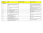


![別紙参照[PDFファイル:34.3KB]](http://vs1.manualzilla.com/store/data/006569641_2-2f8f04c191d63e6daace204b8bd0cdbb-150x150.png)