1
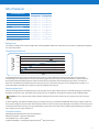
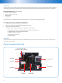
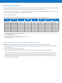
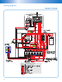
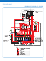
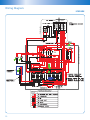
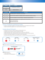
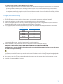
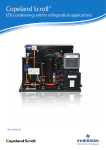
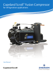
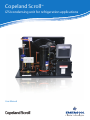
Copeland Scroll
TM
IZSI condensing unit for refrigeration applications
User Manual
Pioneering Technologies For Best-In-Class Products
Emerson Climate Technologies is the world’s leading provider of heating, ventilation, air-conditioning
and refrigeration solutions for residential, commercial, and industrial applications. Leveraging a vast
global network of sales, engineering, and manufacturing, EmersonTM has positioned itself to continue
delivering the HVACR industry with advanced technologies and solutions along with superior technical
support and training services.
For more than 80 years, Emerson has been introducing innovative technologies and solutions to the
HVACR market. From the first semi-hermetic and hermetic compressors in the 1940s and 1950s, to
the high efficiency DiscusTM semi-hermetic and Copeland ScrollTM compressors of the 1980s and 1990s,
Emerson has been the pioneer of the industry. Today, Emerson continues to build upon that success
with new products such as the Copeland ScrollTM Fusion semi-hermetic scroll and Stream line-up of
semi-hermetic reciprocating compressors, both equipped with CoreSenseTM technology for optimal
compressor protection and system diagnostics. Through this, Emerson has developed an unequalled
range of solutions for the refrigeration, heating, and air conditioning markets.
Our Vision:
Emerson Climate Technologies, With Our Partners,
Will Provide Global Solutions To Improve Human Comfort,
Safeguard Food And Protect The Environment.
2
Table of Contents
Disclaimer
04
Nomenclature
04
Bill of Material
05
Physical Layout of the Unit
06
Dimensions and Installation Guidelines
07
Essential Service/Installation Tools, Equipment and Materials
08
Tubing Installation
08
Electrical Installation
09
Wiring Diagram
10
Start-up Leak Test, Evacuation and Charging
16
Unit Operation
18
Maintenance
18
Contact Lists
20
3
Safety Information
Thank you for purchasing the Copeland Scroll™ IZSI indoor condensing unit. We hope that this product meets your refrigeration needs
efficiently and effectively.
Please read through this User Manual thoroughly to familiarize yourself with the installation and commissioning process of this product
and how to use it optimally. Please do read the following information in this page before proceeding with the rest of the manual.
The EmersonTM medium/low temperature refrigeration condensing units should only be installed by suitably qualified and experienced
refrigeration technicians. No responsibility can be accepted for damage caused by inexperienced or inadequately trained site technicians
or improper system design. All instructions and procedures described in this manual are based on good refrigeration trade practices as
applicable to this particular product. The installation contractor may prefer to use variations to these recommendations. However, the
methods described in this manual represent the minimum requirements to avoid any subsequent warranty claims for this equipment and
its components. These instructions do not cover the fundamentals of good electrical or refrigeration practice and are therefore intended
for use only by qualified and/or experienced personnel or technicians.
These instructions are general in nature for this family of products and due to our policy of continuous improvement, some of the details
may not apply to the unit you are installing. If in doubt, please consult your local sales office, quoting unit model, and serial number as
shown on the nameplate. In case of ambiguity, the wiring diagram supplied with each unit takes precedence over the diagram in this
manual.
Important:
The information contained in this manual is critical to the correct operation and maintenance of the condensing unit and should be read
by all persons responsible for the installation, commissioning, and maintenance of this unit.
Safety
The equipment has been designed and manufactured to meet international safety standards but, like any mechanical/electrical
equipment, care must be taken if you are to obtain the best results.
Caution
1. Service and maintenance of this unit, that is, Electrical and Mechanical in nature should be carried out by technically trained and
competent personnel. They should be familiar with Local Standards and Codes of Practice.
2. When carrying out unit maintenance, ensure that the equipment is disconnected from the electrical power supply.
3. Refrigerant used in this unit is classified under the COSHH regulations as an irritant, with set Occupational Exposure Levels (OEL) for
consideration if installed in confined or poorly ventilated areas.
S = Wide Operating
Range
I = Liquid Injection
V = Vapor
D = Digital
N = None
6
A
Nominal Capacity
(Btu/hr)
Base Model
E
-
P
F
Z
-
5
0
Bill of Material
Z = Scroll
C = CR
S = S/H
K = FHP
Condensing Compressor Operating
Series
Type
Range
0
PFZ = 220–240 V
1 Ph–50 Hz
TFM = 380–420 V
3 Ph–50Hz
I
Blank = Mineral Oil
E = POE Oil
S
Chassis Type
Z
Compressor
Nominal Capacity
(Btu/hr)
at 60Hz Rating
Condition
I
I = Indoor Type
CDU
Nomenclature
Oil Charged
Electrical
Code
BOM
The IZSI series indoor type scroll condensing units cover the range of 2 HP to 6 HP. The range is available with many
refrigerant options and is suitable for a wide range of low and medium temperature applications like freezer room and
medium temperature cold room/showcase applications.
4
0
Bill of Material
BOM
Standard BOM Content
500
501*
CoreSense™
✓
✓
Electrical Box
✓
✓
✓
Crank Case Heater
✓
Filter Drier - Soldered Connection
✓
Moisture Indicator / Sight Glass
✓
✓
Dual Pressure Switch
✓
✓
Receiver with Valve
✓
✓
Fan Motor
✓
✓
Heat Exchanger
✓
✓
Compressor with Stub Tube
✓
✓
Compressor with Rotalock Connections
*To be released in the future
Refrigerants
The range is designed for various refrigerants including R404A and R134a. Contact your local sales or Application Engineer
for more information.
Absorption of Moisture
Moisture Absorption
@ 25oC & 50% RH
PPM
1500
POE
1000
500
Mineral Oil
50
100
150
200
250
300
hours
Since POE holds moisture more readily than mineral oil, it is more difficult to remove through the use of a vacuum.
Condensing units supplied by Emerson Climate Technologies contain oil with low moisture content, and this may rise
during the system assembling process. POE oil should not be exposed to the atmosphere longer than 15 minutes. A
filter drier is installed to help maintain the moisture level in the oil less than 50 ppm. If oil is charged into a system, it is
recommended to use POE with a moisture content no higher than 50 ppm.
Receiving Your Unit
All units are shipped with a holding charge of dry nitrogen at a low but positive pressure. Suitable labeling is prominently
displayed on the unit. Two Schraeder type connections are provided for checking the integrity of the holding charge.
Caution! It is very important to check that this holding pressure exists at the time you receive each unit from your
supplier.
If, after checking, you find the holding charge non-existent or low, you should immediately inform your supplier. Failure to
do so could void your claim for other related system faults at a later period. Transit damage is essentially an insurance claim
and not covered under warranty. It is also advisable to inspect the rest of the unit for obvious physical damage and inform
your supplier in case any is discovered.
Standard Features
Wide Operating Envelope for Various Applications
Efficient and Quiet – Key Scroll Attributes
Low Applied Cost – Factory Built
Simple and Reliable – Powered by Copeland ScrollTM with CoreSense™
5
Condenser
Large surface area coil ideally positioned to optimize airflow and heat transfer. Axial fan assembly with finger proof grille
and incorporating an external rotor motor, offering maximum performance while keeping sound levels to a minimum.
ZSI Scroll compressors are comprised of:
• Internal motor protection
• Internal pressure relief valve
• Oil sight glass
• Sump heater
The compressors are mounted to the base plate with the use of vibration reducing grommets.
The refrigeration circuit is supplied with the following:
• Suction and Liquid Line Charging / Pressure Valve
• Low Pressure and High Pressure cut out with manual reset
• CoreSenseTM Injection Controller
– The CoreSenseTM controller, drives the injection EXV and features:
> PD Control to Avoid Overheating and Optimal Compressor Operation
> High Discharge Line Temperature Protection
> Self Diagnostic Sensor Failure
> LEDs for Hardware Check
> Alarm Contact
Electrical
The electrical box construction complies with IP54 weatherproof construction. An electrical contactor and push type
connectors are provided.
Physical Layout of the Unit
Rotalock Valve With
Schraeder Valve for Receiver
Receiver
CoreSenseTM
Filter Drier
Terminal Box
Sight Glass
Dual Pressure
Switch
6
ZSI Scroll
Compressor
Customer Line Connections
Suction Schraeder Valve
Dimensions and Installation Guidelines
Table below shows overall dimension of the units.
CDU Models
HP
IZSI06AE
2.0
IZSI08AE
2.5
IZSI09BE
3.0
IZSI11BE
4.0
IZSI14CE
4.5
IZSI15CE
5.0
IZSI18DE
6.0
Chassis WxDxH (mm)
Single Fan
Dual Fan
716 x 538 x 470
–
738 x 674 x 521
–
738 x 674 x 572
–
–
1045 x 679 x 557
Unit Lifting
• If the unit is dropped, it should immediately be checked for damage.
Caution!
The unit should be lifted from the base and where possible, with all packing and protection in position.
The installation position should be selected with the following points in mind:
• Levelling should be +/- 5 mm.
• Observe airflow and maintenance clearances.
• Pipework and electrical connections are readily accessible.
• Where multiple units are installed, due care should be taken to avoid the discharge air from each unit adversely affecting
other units in the vicinity.
• Ensure there are no obstructions in front of the condenser inlet.
Positioning
• Maintain distance between units to prevent air recirculation.
Caution! Prior to connecting power, ensure that the equipment is installed and level.
It is recommended to have a clearance of at least 500mm between the condenser face and adjacent wall or unit.
Where multiple units are to be installed in the same location, the contractor needs to consider each individual case
carefully. There can be many variations of unit quantities and available space and this manual does not cover all such
possible options. In general terms, air recirculation and local heat build up should be avoided at all times.
Caution! The unit should never be installed adjacent to a dust source (such as a dirty road or extractor fan).
External contamination of the condenser fins lead to high condensing temperatures and will reduce the life of the unit.
7
Essential Service/Installation Tools, Equipment, and Materials
Before start-up, the technician needs to assemble the correct tools and equipment for the task. Apart from the normal
refrigeration service technician tools, electrical test equipment, and hand tools, the following items are essential for the
installation of hermetic refrigeration systems:
Vacuum Pump of sufficient size for the total refrigeration system and capable of pulling a vacuum of at least 100 µmHg
(microns) or 13 Pa. This pump should be fitted with a proper vacuum breaker valve in the event that this pump loses power
supply during the evacuation process.
A Four Port Charging Manifold includes:
• A 3/8” hose to vacuum pump
• All hoses fitted with removable Schraeder depressors
• One compound and one pressure gauge
All equipment should be leak-free, accurate, and reliable.
Clean and sufficient nitrogen gas for leak testing. Clean and new refrigerant gas of sufficient quantity for charging.
Note: Refrigerant cylinders must be the type that can deliver liquid refrigerant until empty.
Oxygen-free Nitrogen and regulators.
Reliable Electronic Vacuum Gauge. A clean and leak-free refrigeration system can only be assured if the initial vacuum is
deep and holds on test. This equipment must meet the standards indicated in the recommended start-up procedures.
Clean and new compressor oil.
• POE Oil is charged in R404A unit. System must use same oil as the condensing unit.
If the recommended oil is not available in your area, contact your nearest distributor/wholesaler for acceptable
alternatives.
Thermometer to measure discharge temperature and suction temperature.
Electronic Leak Detector.
Tubing Installation
• Proper line sizes are necessary for good oil return
–– Need to maintain minimum gas velocities
The compressor oil is constantly pumped through the liquid line, evaporator coil, and back through the suction line in
normal system operation.
Please follow the guidelines listed below to ensure proper lubrication of the compressor by avoiding oil accumulation at
undesirable points in the system:
1. No traps in the suction line are necessary if the condensing unit is level with the indoor evaporator coil or the indoor
evaporator coil is 1.2 m less or lower than the outdoor condensing unit.
2. A trap is necessary in the suction line at the indoor evaporator coil if the indoor evaporator coil is more than 1.2 m below
the outdoor condensing unit.
8
Electrical Installation
All wiring must conform to the provisions of local codes, or in the absence of local codes, an equivalent type wire/contactor
or connectors must be used if any of the originals supplied with the unit needs to be replaced.
A reference table is shown below for unit electrical characteristics. Provide proper power supply to the unit through a circuit
breaker or fused disconnect switch, in accordance with local codes.
All units must be grounded.
Fuses should be sized according to local regulations but should not be larger than indicated in the table
Models
Rated Voltage/
Hz
RLA
Max. Operating
Current
LRA
Contactor
Rating
Min. Circuit
Ampacity
Max.
Fuse
IZSI06AE-PFZ
220V - 240V 50Hz
13.5
13.6
56.6
22.0
16.4
30.0
IZSI08AE-PFZ
220V - 240V 50Hz
14.1
15.6
71.5
22.0
17.8
30.0
IZSI09BE-TFM
380V - 420V 50Hz
6.8
6.7
39.2
21.0
8.5
15.0
IZSI11BE-TFM
380V - 420V 50Hz
9.2
7.5
51.5
21.0
11.5
20.0
IZSI14CE-TFM
380V - 420V 50Hz
9.8
9.2
51.5
21.0
12.2
25.0
IZSI15CE-TFM
380V - 420V 50Hz
10.3
11.9
51.5
21.0
12.8
25.0
IZSI18DE-TFM
380V - 420V 50Hz
13.0
13.7
74.0
21.0
14.8
30.0
Notes:
1. Use copper conductors only. All wiring must comply with local codes for wire sizes. Also, it is suggested that the next larger size wire be used when long runs in excess of 30m.
Refer to the following wiring diagrams when wiring or servicing.
2. R.L.A. = Rated Load Amps.
3. L.R.A. = Compressor Locked Rotor Amps
4. In the event of fuse blowing, investigate the cause. Do not put in a larger fuse.
5. The name plate is located on the outside surface of the unit.
6. All units are in Ampheres
All installation and wiring must be performed by qualified personnel.
Notice: Before the unit is started, the following points must be checked by the installer and/or electrician:
1. Check every electrical connection of “PUSH-ON” or “SCREW-ON” type terminals to ensure these are secured tightly on
their proper post.
2. Review wiring diagrams for proper routing.
3. All wiring must comply with local codes for wire sizes. Refer to the wiring diagrams when wiring or servicing.
A loose terminal will cause local overheating, deteriorating the insulation and causing electrical breakdown. This can
lead to blown fuses, burned wires, burned contact points, and a premature compressor failure. Each electrical contact
has been factory checked, however, connections may loosen up due to vibration in transit. Please be certain that all
electrical connections are tight.
9
Wiring Diagram
IZSI06AE, IZSI08AE
CoreSense Box
CoreSense
Module
OUT PUT
IN PUT
12
18
16
14
13
17
15
19
30
31
2
1
15
L
33
4
5
6
S
CONTACTOR
7
3
R
20
F
26
25
E
N
8
21
33
32
25
29
34
EARTH
S
E
9
10
11
20
17
7
19
C
R
8
5
1
2
30
4
10
5
6
N
C S R
29
9 11
6
13
3
3
2
7
8
L
22 14 16
L
E N
34
28
21
CONNECTIONS CHART
FERRULE No.
ON WIRES
23 24
21 22
25 26
27 28
30 31
9 10 11
10
32 4
9 10 11 12 13 14 15 16 17 18 19
27
24
1
18
USED FOR CONNECTING
L
L
23
RUN
CAPACITOR
ELECTRICAL ACCESSORIES BOX
E
Wiring Diagram
IZSI09BE, IZSI11BE, IZSI14CE, IZSI15CE
CoreSense Box
CoreSense
Module
OUT PUT
IN PUT
12
10
16
14
13
15
17
11
26
25
E
2
14
P
69
1
20
36
CONTACTOR
24
F
34
20
8
7
N
9
35
36
23
E
37
EARTH
7
R
Y B
E
6
9
18
11
3
30
2
1
13
4
5
8
10
28
ELECTRICAL ACCESSORIES BOX
3
19
23
10
1
4
5
6
7
35
16
17
9
11 12 13 14 15 16 17 18 19 20 21
2
3
8
R Y
B
4
37
6 34 27 31 21 69
N
5
E N
R
B Y
R
22
32 29
30
CONNECTIONS CHART
FERRULES No.
ON WIRES
USED FOR CONNECTING
21 22
29 30
23 24
31 32
25 26
4 5 6
27 28
11
Wiring Diagram
IZSI18DE
CoreSense Box
CoreSense
Module
OUT PUT
IN PUT
12
10
16
14
13
15
17
11
26
25
E
3
14
P
69
1
20
36
CONTACTOR
24
24
28
34
E
23
20
8
7
N
9
F
35
23
E
36
37
EARTH
7
R
Y B
E
6
9
18
11
4
5
8
1
2
3
4
19
23 23
13
10
5
6
7
8
16
9 10
3
2
1
35
17
12 13 14 15 16 17 18 19 20 21 22
N
R
R Y B
4
5
6 34 27 31 21
69 37
E N
B Y
32 29
R
22
28
30
CONNECTIONS CHART
FERRULES No.
ON WIRES
21 22
29 30
23 24
31 32
25 26
4 5 6
27 28
12
USED FOR CONNECTING
11
30
ELECTRICAL ACCESSORIES BOX
2
Pressure Cut Out Settings
Please ensure following setting for the cut outs for the safe operation of the unit:
Refrigerant
Maximum
Condensing
Temp.
LP
Cut Out
R404A
60°C
1.0 bar
Cut In
Minimum
Evaporating
Temp.
HP
Cut Out
Cut In
2.7 bar
-30°C
29.6 bar
24.1 bar
CoreSense™ Controller
Function Description:
The board will be used to turn the compressor on/off
based on the demand signal from low pressure switch and
thermostat. The board will control Liquid Injection through
an EXV based on a temperature sensor placed on the
discharge line.
EXV Driver
DLT Sensor
UP
LED3
LED2
Dipswitch Setting
• SW1 is used to control the liquid injection setpoint
and cut out. Do not change settings and ensure that a
replacement board is set correctly.
• SW2 and SW3 are not functional in IZSI units.
DOWN
RESET
LED1
SW3
LED4
Dipswitch
Factory Setting
SW1 bit1
OFF
SW1 bit2
OFF
SW2 and SW3
Not used
SW2
SW1
Board Power Supply
Input Terminals (From
12VAC Transformer)
Demand
Reserved
Compressor
Contactor
Dry Contact - Alarm
Output Terminal
13
Board Operation - EXV Testing
Button
Function
Up
To operate EXV manually
Down
Reset
Resets the board
LED Display
Description
1
(Yellow Green)
LED Blinking Pattern Indicates DLT Sensor Status
2
(Yellow Green)
LED2 and LED3 Combination and Blinkng Patterns Indicate EXV Opening or Closing
3
(Yellow Green)
LED2 and LED3 Blink Once When Entering or Exiting EXV Manual Operation
LED4 Turns On as an Alarm when Triggered by any of the following:
1) DLT overheat protection
2) DLT sensor open circuit
3) DLT sensor short circuit
4
(Red)
Operation: Shift Between Auto Mode and Test Mode
• Push “Up” and “Down” together for 5 seconds to shift between Control Mode and Auto Mode
• LED2 and LED3 flashing together once means the shift is successful
Operation: Operate EXV Manually
•
•
•
•
•
•
Short Push (< 2s) “Up” or “Down” to open or close EXV by one step
Long Push “Up” and “Down” to open and close EXV rapidly
LED2 will flash when EXV is opening and will remain on when EXV is fully open
LED3 will flash when EXV is closing and will remain on when EXV reaches minimum opening
Push “Up” and “Down” together for 5 seconds to revert to Auto Mode
Board will automatically revert to Auto operation after 10 minutes from last manual button push
Opening
Fully Open
Closing
LED 2
LED 3
LED 2
LED 3
LED 2
Flash
OFF
ON
OFF
OFF
Diagnostic Function of the Board
LED1: Status Indicator of Discharge Line Temperature Sensor
Circuit Open/Short
Flash
Flash
Repeat
5 Seconds
3 Times
3 Times
LED4: Warning Signal
• Overheat Protection
• Sensor Failure, Circuit Open/Short
14
ON
Warning
OFF
Normal
Minimum Opening
LED 3
Flash
LED 2
LED 3
OFF
ON
Initial Start Up of Condensing Unit
Utmost care must be taken while handling the scroll condensing unit. Please go through the contents below to ensure
proper handling:
Refrigerant Charging
• Charge liquid into high side of system.
• DO NOT vapor charge the system through the suction, otherwise compressor will overheat.
• If top up is necessary, bleed some liquid refrigerant into low side when the compressor is running.
CAUTION: Low Side Vapor Charging will damage the scroll set
Application Tips for Scroll Compressors
• Do not use compressor to pull vacuum
• Never use the compressor to suck oil into the system
• Do not test compressor by closing suction valve
• Do not set low pressure switch below 0 bar
• Do not bypass LP controls
• Do not pump down below 0 bar
• Reverse Rotation
- Incorrect rotation can be identified by:
> Low current, noise, balanced suction, and discharge pressure
- Correct by interchanging any two phases
- Short-term reverse rotation will not damage the compressor
15
Start-up Leak Test, Evacuation, and Charging
The following assumes the condensing unit to be leak-free on arrival. That is an important step before proceeding with the
following.
Leak test is particularly important for field-connected systems. Typically, field systems lose as much as 20%–30% of their
refrigeration charge annually. This is not only an unnecessary expense but also damages the environment. Compressor oil
can be lost at the same time as refrigerant and eventually lead to compressor failure. (Time spent on leak test will eventually
reduce the time spent on the evacuation process).
Ensure that all service valves are open during the leak test process. It is important to recheck all joints within the unit as well
as the external joints.
Initial Pressure Test (by vacuum and nitrogen)
Step-by-Step:
1. Use a 4-port gauge manifold with 3/8” hose and connections to the vacuum pump. The vacuum gauge does not have to
be connected for this part of the process.
2. Connect the gauges to service ports provided on receiver valve and suction tube.
In order to remove any non-condensable that may have entered the system during installation, follow these steps:
• Start the vacuum pump. The evaporator fan should be running and the compressor crankcase heater is energized at
this point. This will involve powering up the unit so it is important to disconnect the live feed wire to the compressor
contactor (so the compressor cannot run and the crankcase heater can be energized).
3. Open both valves on the manifold and then open the main vacuum valve on the pump. Run the system until the vacuum
level of -0.85 bar (as read on manifold gauge) is achieved.
4. Shut off the main vacuum pump valve. Check for vacuum rise using the manifold compound gauge. A rise would indicate
a large leak.
5. If vacuum holds for 10 minutes, break vacuum with nitrogen and pressurize to 20 bar. Check for leaks and repair leakage
once detected.
Leak Test (by nitrogen pressure)
Release nitrogen from system. Start vacuum pump and open main pump valve.
Evacuation
Note that the following procedure is based upon achieving an actual system vacuum standard and it is NOT TIMEDEPENDENT!
Step-by-Step:
1. Check suction capability of the vacuum pump with a gauge before commencing evacuation process. The vacuum pump
must be rated to achieve a vacuum level of at least 100 µmHg (microns) or 13 Pa.
2. Connect the vacuum gauge to the system.
3. It is recommended to carry out the evacuation process three times as detailed below:
Start the vacuum pump and then open the main valve. It is assumed that the crankcase heater is still energized and the
compressor cannot start.
Caution: Ensure that the vacuum pump cannot be switched off during evacuation – otherwise the pump may lose
its lubrication oil to the system and contaminate it. Therefore, the pump must have a Vacuum Breaker fitted to it.
• Step 1 Evacuation: Evacuate to 1500 µmHg (microns) or 200 Pa and break vacuum to 0.1 bar with Nitrogen
• Step 2 Evacuation: Same as in Step 1
• Step 3 Evacuation: Leave the pump running while checking the vacuum regularly
16
The target system vacuum is 500 µmHg (microns) or 67 Pa.
• Once the target vacuum level is reached, the quality of the vacuum within the system must be tested. This is achieved
by shutting off the main pump valve, allowing the internal system pressure to rise, and recording the time taken for
the vacuum to rise by no more than 300 µmHg (microns) or 40 Pa within 30 minutes. (i.e. to 100 μmHg (microns) or
13.3 Pa). Evacuation is only complete once the vacuum quality is achieved. Close the manifold valves tightly. Close the
pump main valve, switch off, and remove the vacuum pump.
Charging and Commissioning
Step-by-Step:
1. Ensure that there is no power supply to the unit. Hence, it is acceptable to leave the crankcase heater off.
2. Connect the refrigerant cylinder to main service hose and purge line at the manifold end.
3. Invert the refrigerant cylinder if necessary to ensure only liquid refrigerant can be charged into the system. This will be
charged through the high pressure side of the manifold and liquid service valve.
4. The refrigerant cylinder should be weighed at this point to be able to record the final refrigerant charge. Refer to the
table below for the approximate holding capacity of receiver is at 32oC when it is 80% full. Dipswitch
R404A
IZSI06AE
1.9
IZSI08AE
1.9
IZSI09BE
5.5
IZSI11BE
5.5
IZSI14CE
5.5
IZSI15CE
5.5
IZSI18DE
7.2
5. Now open the liquid service valve (off the back seat). In warm ambients, with a good vacuum in the system and the
refrigerant cylinder inverted, it may not be necessary to run the compressor.
6. In cooler ambients, it may be necessary to run the compressor in order to complete charging.
IMPORTANT! TO BE CLEARLY UNDERSTOOD PRIOR TO RUNNING ANY SCROLL COMPRESSOR!
Scroll compressor systems should be charged as quickly as possible by bleeding liquid refrigerant into the suction
line with the compressor running.
DO NOT VAPOR CHARGE SCROLL CONDENSING UNIT SYSTEM!
7. The system needs to be operated down to its set point before you can be sure that the charge is correct. It is at this
point that the normal refrigeration operational checks can be carried out—such as checking the liquid line sight glass for
bubbles and the operating pressures.
8. If the system is still short of the refrigerant, bleed liquid refrigerant into the suction side with the compressor running.
9. Check the oil level and add oil if necessary.
17
Unit Operation
Before starting the unit, ensure the following:
• All the electrical connections are correct and as per the recommended wiring diagrams
• All low side tubings are properly insulated
• Leak check is done and unit is pre-charged with refrigerant through high side
• Check for superheat setting on the expansion valve (TXV) appropriate or not
Adding refrigerant on a cold weather results to an overcharged unit, which may then trip out on high pressure limit during
warm weather.
Suction Superheat should be 10–15 K for reliable operation.
WARNING: Remember that the refrigerant is under pressure. Always wear protective equipment, i.e. safety glasses
or goggles and gloves when working with refrigerant, and guard against refrigerant spraying into the face or skin. Line
pressures on an operating conditioning unit will vary with outdoor temperatures. As outdoor temperatures rise, pressures
will also rise.
CAUTION: DO NOT, UNDER ANY CIRCUMSTANCES, HEAT THE REFRIGERANT CYLINDER WITH A TORCH OR BY ANY
OTHER MEANS OTHER THAN WARM WATER. EXCESSIVE PRESSURES GENERATED IN THIS MANNER MAY WEAKEN THE
REFRIGERANT CONTAINER AND RESULT TO A CYLINDER EXPLOSION!
Maintenance
Condenser Fins
Condenser fins become dirty over time as ambient air is induced to the condenser. Dirty coil surfaces result in high
condensing temperatures and poor unit performance. Regular cleaning is recommended with frequency depending on
the installation and the surrounding environment. As a general guide, it is advisable to do this at least once every two
months.
Fins should be cleaned with liquid detergent diluted with clean water. Before washing, a light brush downward (in the
direction of the fins) should be done to remove heavy deposits.
Electrical Connections
Check tightness of electrical connections occasionally.
Routine Leak Test
All joints should be checked for leaks during site visits. All joints should be leak tested once-a-year.
Condenser Fan(s) and Motor(s)
An annual inspection of these items is recommended. Fastenings may loosen, bearings may wear, and fans may require
cleaning of solid deposits which can cause imbalance.
WARNING:
TURN OFF OR DISCONNECT THE ELECTRICAL POWER SOURCE BEFORE CLEANING THE CONDENSER COIL OR DOING
MAINTENANCE.
18
General Information
Technical data are correct at the time of printing. Updates may occur, and should you need confirmation of a specific value,
please contact Emerson Climate Technologies stating clearly the information required.
Emerson Climate Technologies cannot be held responsible for errors in capacities, dimensions, etc., stated herein.
Products, specifications, and data in this literature are subject to change without notice.
The information given herein is based on data and tests which Emerson Climate Technologies believes to be reliable
and which are in accordance with today’s technical knowledge. It is intended for use by persons having the appropriate
technical knowledge and skill, at their own discretion and risk. Our products are designed and adapted for fixed locations.
For mobile applications, failures may occur.
The suitability for this has to be assured from the plant manufacturer, which may include making appropriate tests.
Note:
The components listed in this catalogue are not released for use with caustic, poisonous or flammable substances.
Emerson Climate Technologies cannot be held responsible for any damage caused by using these substances.
19
Contact Lists
Asia Pacific Headquarters
Emerson Climate Technologies
Suite No. 2503-8, 25/F,
Exchange Tower, 33 Wang Chiu Road,
Kowloon Bay, Kowloon, Hong Kong
Tel: (852) 2866 3108
Fax: (852) 2520 6227
Australia
Emerson Climate Technologies Australia
Pty Ltd
356 Chisholm Road
Auburn NSW 2144, Australia
Tel: (612) 9795 2800
Fax: (612) 9738 1699
China - Beijing
Emerson Climate Technologies (Suzhou)
Co. Ltd
Beijing Sales Office
Room 1017 JianWei Building,
66 Nan Lishi Road, XiCheng District,
Beijing, PRC
Tel: (8610) 5763 0488
Fax: (8610) 5763 0499
China - Guangzhou
Emerson Climate Technologies (Suzhou)
Co. Ltd
Guangzhou Sales Office
508-509 R&F Yinglong Plaza,
No. 76 Huangpu Road West,
Guangzhou, PRC
Tel: (8620) 2886 7668
Fax: (8620) 2886 7622
China - Shanghai
Emerson Climate Technologies
(Suzhou) Co. Ltd
Shanghai Sales Office
1801 Building B, New CaoHeJing
International Business Center,
391Guiping Rd, Shanghai, PRC
Tel: (8621) 3418 3968
India - Mumbai
Emerson Climate Technologies (India) Ltd
Delphi B-Wing, 601-602, 6th Floor
Central Avenue, Hiranandani Business Park,
Powai, Mumbai 400076
Tel: (9122) 2500 6630 / 2500 6632
Fax: (9122) 2500 6570
India - PUNE
Emerson Climate Technologies (India) Ltd
Plot No. 23, Rajiv Gandhi Infotech Park,
Phase - II, Hinjewadi,
Pune 411 057, Maharashtra, India
Tel: (9120) 2553 4988
Fax: (9120) 2553 6350
Indonesia
PT Emerson Indonesia
Wisma 46 - Kota BNI, 16th Floor, Suite 16.01,
Jl. Jend.Sudirman Kav.1.
Jakarta 10220, Indonesia
Tel: (6221) 2513003
Fax: (6221) 2510622
Japan
Emerson Japan Ltd
Shin-yokohama Tosho Building
No. 3-9-5 Shin-Yokohama, Kohoku-ku
Yokohama 222-0033 Japan
Tel: (8145) 475 6371
Fax: (8145) 475 3565
Malaysia
Emerson Electric (Malaysia) Sdn. Bhd.
Level M2, Blk A, Menara PKNS-PJ
Jalan Yong Shook Lin
46050 Petaling Jaya, Selangor, Malaysia
Tel: (603) 7949 9222
Fax: (603) 7949 9333
EmersonClimateAsia.com
Aus 01 A01 10 – R00 Issued 04/2014 – GSCAA043
Emerson, CoreSense Diagnostics and Copeland Scroll Fusion are trademarks of Emerson Electric Co. or one of its affiliated companies.
©2014 Emerson Climate Technologies, Inc. All rights reserved.
Middle East & Africa
Emerson Climate Technologies
PO Box 26382
Jebel Ali Free Zone – South
Dubai, UAE
Tel: (9714) 811 8100
Fax: (9714) 886 5465
Philippines
Emerson Climate Technologies
23rd Floor San Miguel Properties Centre
#7 St. Francis Street, Ortigas Center,
Mandaluyong City, Philippines
Tel: (632) 689 7200
South Korea
Emerson Electric Korea Ltd.
3F POBA Gangnam Tower, 119 Nonhyun-Dong, Gangnam-Gu, Seoul 135-010
Korea
Tel: (822) 3483 1500
Fax: (822) 592 7883
Taiwan
Emerson Electric (Taiwan) Co. Ltd
3F No. 2 DunHua South Road Sec.1,
Taipei (105), Taiwan
Tel: (8862) 8161 7688
Fax: (8862) 81617614
Thailand - Bangkok
Emerson Electric (Thailand) Ltd
34th Floor, TCIF Tower,
1858/133, Bangna Trad,
Bangkok 10260, Thailand
Tel: (662) 716 4700
Fax: (662) 751 4241
Vietnam
Emerson Climate Technologies - Vietnam
Suite 307-308,
123 Truong Dinh St., Dist.3
Ho Chi Minh, Vietnam
Tel: (84) 908 009 189
Scan With Your
Smartphone For
More Information