1
Optional DIO Cables
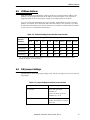
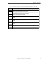
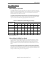
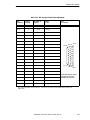
Table 13-4. DIO P1 Input Cable Pin Assignments
Pin
Number
Signal
Group
Module #1
Signala
Wire
Color
P1–15
1
1033
red/white
P1–6
1
1034
orange
P1–16
1
1035
green/white
P1–7
1
1036
blue
P1–17
1
1037
blue/white
P1–8
1
1038
white/black
P1–18
1
1039
black/red
P1–9
1
1040
red/black
P1–25
1
group 1 return
blue/red
P1–26
1
group 1 return
red/green
P1–10
2
1041
green/black
P1–1
2
1042
black
P1–11
2
1043
orange/black
P1–2
2
1044
white
P1–12
2
1045
blue/black
P1–3
2
1046
red
P1–13
2
1047
black/white
P1–4
2
1048
green
P1–19
2
group 2 return
white/red
P1–20
2
group 2 return
orange/red
a
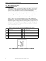
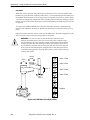
Pin
Locations
Pin 26
Pin 18
Pin 9
Pin 19
Pin 10
Pin 1
P1 26-Pin Female Input
Connector on DIO
Module Front Panel
The signal numbers for modules 2 –7 increase by 32 for each additional module; see
Table 13-8.
Adept MV Controller User’s Guide, Rev C
149