1
D811509_01
INSTALLATION MANUAL
Thank you for buying this product, our company is sure that you will be more
than satisfied with its performance.
This product is supplied with an “Instruction Manual” which should be read
carefully as it provides important information about safety, installation, operation and maintenance.
This product complies with recognised technical standards and safety regulations. We declare that it is in conformity with the following European Directives:
89/336/EEC, 73/23/EEC and subsequent amendments.
1) GENERAL SAFETY
WARNING! An incorrect installation or improper use of the product
can cause damage to persons, animals or things.
• The “Warnings” leaflet and “Instruction booklet” supplied with this
product should be read carefully as they provide important information
about safety, installation, use and maintenance.
• Scrap packing materials (plastic, cardboard, polystyrene etc) according
to the provisions set out by current standards. Keep nylon or polystyrene
bags out of children’s reach.
• Keep the instructions together with the technical brochure for future
reference.
• This product was exclusively designed and manufactured for the use
specified in the present documentation. Any other use not specified in
this documentation could damage the product and be dangerous.
• The Company declines all responsibility for any consequences resulting
from improper use of the product, or use which is different from that
expected and specified in the present documentation.
• Do not install the product in explosive atmosphere.
• The construction components of this product must comply with the following
European Directives: 89/336/CEE, 73/23/EEC, 98/37/EEC and subsequent amendments. As for all non-EEC countries, the above-mentioned
standards as well as the current national standards should be respected
in order to achieve a good safety level.
• The Company declines all responsibility for any consequences resulting
from failure to observe Good Technical Practice when constructing closing
structures (door, gates etc.), as well as from any deformation which might
occur during use.
• The installation must comply with the provisions set out by the following
European Directives: 89/336/CEE, 73/23/EEC, 98/37/EEC and subsequent
amendments.
• Disconnect the electrical power supply before carrying out any work on
the installation. Also disconnect any buffer batteries, if fitted.
• Fit an omnipolar or magnetothermal switch on the mains power supply,
having a contact opening distance equal to or greater than 3,5 mm.
• Check that a differential switch with a 0.03A threshold is fitted just before
the power supply mains.
• Check that earthing is carried out correctly: connect all metal parts for
closure (doors, gates etc.) and all system components provided with an
earth terminal.
• Fit all the safety devices (photocells, electric edges etc.) which are needed
to protect the area from any danger caused by squashing, conveying and
shearing.
• Position at least one luminous signal indication device (blinker) where it
can be easily seen, and fix a Warning sign to the structure.
• The Company declines all responsibility with respect to the automation safety
and correct operation when other manufacturers’ components are used.
• Only use original parts for any maintenance or repair operation.
• Do not modify the automation components, unless explicitly authorised
by the company.
• Instruct the product user about the control systems provided and the
manual opening operation in case of emergency.
• Do not allow persons or children to remain in the automation operation area.
• Keep radio control or other control devices out of children’s reach, in
order to avoid unintentional automation activation.
• The user must avoid any attempt to carry out work or repair on the automation system, and always request the assistance of qualified personnel.
• Anything which is not expressly provided for in the present instructions,
is not allowed.
• Installation must be carried out using the safety devices and controls
prescribed by the EN 12978 Standard.
2) GENERAL OUTLINE
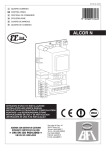
ALCOR N mod. control unit has been designed to be applied on swing gates.
It can control one or two operators.
3) TECHNICAL DATA
Power supply: ...............................................................230V±10%, 50Hz(*)
Mains insulation/very low voltage: ....................................> 4MΩ, 500V
Working temperature:................................................................ -10 / +55°C
ENGLISH
Dielectric strength:…. .......................mains/low voltage 3750V~ for 1 minut
Maximum motor power...........................................................1 motor 300W
................................................................................2 motors 300W + 300W
Supply to accessories: . ................................. 24V~, (0.2A max absorption)
Incorporated Rolling-Code radio receiver: . ............. Frequency 433.92MHz
Coding: ...............................................Rolling-Code Algorithm to be cloned
No. combinations:........................................................................... 4 milliard
Antenna impedance:............................................................ 50Ohm (RG58)
Max no. radio transmitters to be memorised:............................................ 63
Dimensions: ...............................................................................see figure 1
(* other voltages available on request)
4) TERMINAL BOARD CONNECTIONS (Fig.2)
For the wiring diagram and the cable section, make reference to the operator’s manual.
WARNING – During the wiring and installation operations, refer to the current
standards as well as principles of good technical practice.
Wires powered at different voltages must be physically separated, or suitably
insulated with at least 1 mm extra insulation. The wires must be clamped by
an extra fastener near the terminals, for example by bands.
All the connection cables must be kept at an adequate distance from the
dissipator.
Connect the yellow/green conductor of the power supply cable to the earth terminal.
230V cables must be physically separate from the safety very low voltage circuits.
Keep the mains voltage connections definitely separate from the (24V) very
low voltage connections.
The capacitors inside the control unit must be positioned in such a way
as not to decrease the surface and air distances with respect to the safety
very low voltage.
WARNING! For connection to the mains, use a multipolar cable with a
minimum of 3x1.5mm2 cross section and complying with the previously mentioned regulations. For example, if the cable is out side (in the
open), it has to be at least equal to H07RN-F, but if it is on the inside
(or outside but placed in a plastic cable cannel) it has to be or at least
egual to H05VV-F with section 3x1.5mm2.
1-2 Power supply 230V +/- 10% 50/60 Hz (Neutral wire to terminal 1).
3-4-5 M1 motor connection (terminal 4 common wire, terminals 3-5 motor
and capacitor operation).
1-4 Blinker connection 230V
6-7-8 M2r motor connection (terminal 7 common wire, terminals 6-8 motor
and capacitor operation).
1-7 Electric lock connection 230V mod. EBP.
9-10 Input for START Button (N.O.).
9-11 Input for STOP Button (N.C.). If not used, leave bridged.
9-12 Input for Photocell (N.C.). If not used, leave bridged.
9-13 Input with function selectable from DSW9:
with DSW9 OFF, Input for Opening Limit Switch (N.C.). If not used,
leave bridged.
with DSW9 ON Input for OPEN Button (N.O.).*
9-14 Input with function selectable from DSW9 and DSW10:
with DSW9 OFF, Input for Closing Limit Switch (N.C.). If not used,
leave bridged.
with DSW9 ON and DSW10 OFF, Input for CLOSE Button (N.O.).*
with DSW9 ON and DSW10 ON, Input for PEDESTRIAN Button
(N.O.). The pedestrian command is active from gate fully closed; if the
gate is not closed, the PEDESTRIAN button carries out the START
functions.*
15-16Output 24V for accessory power supply 200mA MAX.
17-18 Output for second radio channel, N.O. contact (24V / 1A max.). If an
external receiver is used, it must be a double-channel receiver.
A dry N.O. contact must be electrically connected to the terminals.
19-20Input for receiver antenna (20 Braid, 19 Signal).
*With operation without limit switches, the motors remain active for the
working time set.
RX Connector for the external receiver board.
5) LED (Fig.3)
The ALCOR N control units are provided with a series of self-diagnosis
LEDs which control all the functions.
POWER:Led for power supply on.
OP: Led for Signal indication of Motors active on Opening / Led for
Radio Programming.
CL: Led for Signal indication of Motors active on Closing.
START: It comes on with the START command.
STOP: It goes off with the photocells not aligned or in the presence of
obstacles.
SWO: Led for signal indication of input 13 status:
led on= input closed, led off= input open.
ALCOR N-