1
UM1058
User manual
STEVAL-ILL029V2/STEVAL-CBP007V1: front panel demo with
STLED325 and STMPE24M31 based touch panel
Introduction
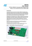
This document explains the operation of the front panel demonstration board based on the
advanced LED controller driver STLED325 and 8-bit microcontroller STM8S as I2C master.
This system can be operated along with the STMPE24M31-based touch panel or the
mechanical keys. The objective of this board is to demonstrate the features of the
STLED325 LED controller driver, such as key scanning, RTC, IR decoding, standby
management, etc., as well as features of the advanced S-Touch device STMPE24M31 to fit
the market segment of DVD players, DVD recorders, set-top boxes, washing machines, etc.,
keeping the system cost as low as possible.
The system can be operated using the various touchkeys or mechanical front panel keys
provided on the system, as well as by remote control. System I/O is handled completely by
STLED325 and STMPE24M31 with minimal load on the host processor. The system can be
operated in two modes: touch interface mode or standalone mode (with mechanical keys on
STEVAL-ILL029V2). On power-up, the system automatically detects the presence of the
touch interface daughter card (STEVAL-CBP007V1) and goes into touch interface mode. If
there is no touch card plugged in, the system enters standalone mode and can be operated
using mechanical keys.
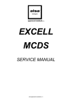
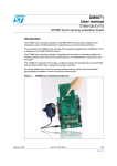
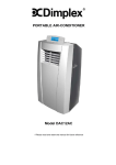
Figure 1.
May 2011
STLED325 front panel demo with STMPE24M31 touch interface
Doc ID 010039 Rev 1
1/34
www.st.com
Contents
UM1058
Contents
1
Features . . . . . . . . . . . . . . . . . . . . . . . . . . . . . . . . . . . . . . . . . . . . . . . . . . . 5
2
Hardware description . . . . . . . . . . . . . . . . . . . . . . . . . . . . . . . . . . . . . . . . 6
3
4
5
2/34
2.1
Power supply unit . . . . . . . . . . . . . . . . . . . . . . . . . . . . . . . . . . . . . . . . . . . . 8
2.2
7-segment (+decimal point) and discrete LED display . . . . . . . . . . . . . . . . 9
2.3
Front panel keys / wake-up mechanical keys . . . . . . . . . . . . . . . . . . . . . . . 9
2.4
DIP switch / external interface connector . . . . . . . . . . . . . . . . . . . . . . . . . 10
2.5
IR sensor connector . . . . . . . . . . . . . . . . . . . . . . . . . . . . . . . . . . . . . . . . . 10
2.6
Interrupt LED . . . . . . . . . . . . . . . . . . . . . . . . . . . . . . . . . . . . . . . . . . . . . . 10
2.7
Interface connectors . . . . . . . . . . . . . . . . . . . . . . . . . . . . . . . . . . . . . . . . . 10
2.8
Touch pads / 8-channel touch status type rotator . . . . . . . . . . . . . . . . . . . 10
Getting started . . . . . . . . . . . . . . . . . . . . . . . . . . . . . . . . . . . . . . . . . . . . . 11
3.1
Package content . . . . . . . . . . . . . . . . . . . . . . . . . . . . . . . . . . . . . . . . . . . . 11
3.2
System requirements . . . . . . . . . . . . . . . . . . . . . . . . . . . . . . . . . . . . . . . . 11
3.3
Powering on the system . . . . . . . . . . . . . . . . . . . . . . . . . . . . . . . . . . . . . . 11
3.4
Startup display sequence / default setting of the system . . . . . . . . . . . . . 11
System features (touch board connected) . . . . . . . . . . . . . . . . . . . . . . 12
4.1
Channel number - brightness level display mode . . . . . . . . . . . . . . . . . . . 12
4.2
RTC operation . . . . . . . . . . . . . . . . . . . . . . . . . . . . . . . . . . . . . . . . . . . . . 12
4.2.1
Display time . . . . . . . . . . . . . . . . . . . . . . . . . . . . . . . . . . . . . . . . . . . . . . 12
4.2.2
Display date . . . . . . . . . . . . . . . . . . . . . . . . . . . . . . . . . . . . . . . . . . . . . . 13
4.2.3
Set time . . . . . . . . . . . . . . . . . . . . . . . . . . . . . . . . . . . . . . . . . . . . . . . . . 13
4.2.4
Set date . . . . . . . . . . . . . . . . . . . . . . . . . . . . . . . . . . . . . . . . . . . . . . . . . 13
4.2.5
Set alarm . . . . . . . . . . . . . . . . . . . . . . . . . . . . . . . . . . . . . . . . . . . . . . . . 13
4.2.6
Alarm condition display . . . . . . . . . . . . . . . . . . . . . . . . . . . . . . . . . . . . . 13
4.3
Demo mode . . . . . . . . . . . . . . . . . . . . . . . . . . . . . . . . . . . . . . . . . . . . . . . 14
4.4
Remote control operation . . . . . . . . . . . . . . . . . . . . . . . . . . . . . . . . . . . . . 14
4.5
Standby mode . . . . . . . . . . . . . . . . . . . . . . . . . . . . . . . . . . . . . . . . . . . . . 15
System features (touch interface not connected) . . . . . . . . . . . . . . . . 17
Doc ID 010039 Rev 1
UM1058
6
7
8
Contents
5.1
Brightness adjustment through potentiometer . . . . . . . . . . . . . . . . . . . . . 17
5.2
Channel number - brightness level display mode . . . . . . . . . . . . . . . . . . . 17
5.3
RTC operation . . . . . . . . . . . . . . . . . . . . . . . . . . . . . . . . . . . . . . . . . . . . . 17
5.3.1
Display time . . . . . . . . . . . . . . . . . . . . . . . . . . . . . . . . . . . . . . . . . . . . . . 17
5.3.2
Display date . . . . . . . . . . . . . . . . . . . . . . . . . . . . . . . . . . . . . . . . . . . . . . 17
5.3.3
Set time . . . . . . . . . . . . . . . . . . . . . . . . . . . . . . . . . . . . . . . . . . . . . . . . . 18
5.3.4
Set date . . . . . . . . . . . . . . . . . . . . . . . . . . . . . . . . . . . . . . . . . . . . . . . . . 18
5.3.5
Set alarm . . . . . . . . . . . . . . . . . . . . . . . . . . . . . . . . . . . . . . . . . . . . . . . . 18
5.3.6
Alarm condition display . . . . . . . . . . . . . . . . . . . . . . . . . . . . . . . . . . . . . 18
5.4
Demo mode . . . . . . . . . . . . . . . . . . . . . . . . . . . . . . . . . . . . . . . . . . . . . . . 18
5.5
Remote control operation . . . . . . . . . . . . . . . . . . . . . . . . . . . . . . . . . . . . . 18
5.6
Standby mode / hot keys . . . . . . . . . . . . . . . . . . . . . . . . . . . . . . . . . . . . . 19
Schematics . . . . . . . . . . . . . . . . . . . . . . . . . . . . . . . . . . . . . . . . . . . . . . . 20
6.1
STEVAL-ILL029V2 schematics . . . . . . . . . . . . . . . . . . . . . . . . . . . . . . . . 20
6.2
STEVAL-CBP007V1 . . . . . . . . . . . . . . . . . . . . . . . . . . . . . . . . . . . . . . . . . 25
Bill of material . . . . . . . . . . . . . . . . . . . . . . . . . . . . . . . . . . . . . . . . . . . . . 28
7.1
BOM STEVAL-ILL029V2 . . . . . . . . . . . . . . . . . . . . . . . . . . . . . . . . . . . . . 28
7.2
BOM STEVAL-CBP007V1 . . . . . . . . . . . . . . . . . . . . . . . . . . . . . . . . . . . . 32
Revision history . . . . . . . . . . . . . . . . . . . . . . . . . . . . . . . . . . . . . . . . . . . 33
Doc ID 010039 Rev 1
3/34
List of figures
UM1058
List of figures
Figure 1.
Figure 2.
Figure 3.
Figure 4.
Figure 5.
Figure 6.
Figure 7.
Figure 8.
Figure 9.
Figure 10.
Figure 11.
Figure 12.
Figure 13.
Figure 14.
Figure 15.
Figure 16.
Figure 17.
Figure 18.
Figure 19.
Figure 20.
Figure 21.
Figure 22.
Figure 23.
Figure 24.
Figure 25.
Figure 26.
4/34
STLED325 front panel demo with STMPE24M31 touch interface . . . . . . . . . . . . . . . . . . . . 1
STEVAL-ILL029V2 demonstration board front view . . . . . . . . . . . . . . . . . . . . . . . . . . . . . . . 6
STEVAL-ILL029V2 demonstration board rear view . . . . . . . . . . . . . . . . . . . . . . . . . . . . . . . 6
STEVAL-CBP007V1 front view. . . . . . . . . . . . . . . . . . . . . . . . . . . . . . . . . . . . . . . . . . . . . . . 6
STEVAL-CBP007V1 rear view . . . . . . . . . . . . . . . . . . . . . . . . . . . . . . . . . . . . . . . . . . . . . . . 7
STLED325 board with STEVAL-CBP007V1 . . . . . . . . . . . . . . . . . . . . . . . . . . . . . . . . . . . . . 7
DC power jack . . . . . . . . . . . . . . . . . . . . . . . . . . . . . . . . . . . . . . . . . . . . . . . . . . . . . . . . . . . 8
7-segment LED display. . . . . . . . . . . . . . . . . . . . . . . . . . . . . . . . . . . . . . . . . . . . . . . . . . . . . 9
Discrete LEDs . . . . . . . . . . . . . . . . . . . . . . . . . . . . . . . . . . . . . . . . . . . . . . . . . . . . . . . . . . . . 9
External interface connector . . . . . . . . . . . . . . . . . . . . . . . . . . . . . . . . . . . . . . . . . . . . . . . . 10
Alarm display . . . . . . . . . . . . . . . . . . . . . . . . . . . . . . . . . . . . . . . . . . . . . . . . . . . . . . . . . . . 14
Example RC5 remote . . . . . . . . . . . . . . . . . . . . . . . . . . . . . . . . . . . . . . . . . . . . . . . . . . . . . 15
Entering into standby . . . . . . . . . . . . . . . . . . . . . . . . . . . . . . . . . . . . . . . . . . . . . . . . . . . . . 16
System is in standby . . . . . . . . . . . . . . . . . . . . . . . . . . . . . . . . . . . . . . . . . . . . . . . . . . . . . . 16
STLED325 section . . . . . . . . . . . . . . . . . . . . . . . . . . . . . . . . . . . . . . . . . . . . . . . . . . . . . . . 20
Microcontroller section . . . . . . . . . . . . . . . . . . . . . . . . . . . . . . . . . . . . . . . . . . . . . . . . . . . . 21
Keyscan circuit . . . . . . . . . . . . . . . . . . . . . . . . . . . . . . . . . . . . . . . . . . . . . . . . . . . . . . . . . . 22
Connectors . . . . . . . . . . . . . . . . . . . . . . . . . . . . . . . . . . . . . . . . . . . . . . . . . . . . . . . . . . . . . 22
Power supply section . . . . . . . . . . . . . . . . . . . . . . . . . . . . . . . . . . . . . . . . . . . . . . . . . . . . . 23
Discrete LED. . . . . . . . . . . . . . . . . . . . . . . . . . . . . . . . . . . . . . . . . . . . . . . . . . . . . . . . . . . . 23
Seven segment LED . . . . . . . . . . . . . . . . . . . . . . . . . . . . . . . . . . . . . . . . . . . . . . . . . . . . . . 24
STMPE24M31 section . . . . . . . . . . . . . . . . . . . . . . . . . . . . . . . . . . . . . . . . . . . . . . . . . . . . 25
LED section . . . . . . . . . . . . . . . . . . . . . . . . . . . . . . . . . . . . . . . . . . . . . . . . . . . . . . . . . . . . 26
Connectors . . . . . . . . . . . . . . . . . . . . . . . . . . . . . . . . . . . . . . . . . . . . . . . . . . . . . . . . . . . . . 26
Touchkeys . . . . . . . . . . . . . . . . . . . . . . . . . . . . . . . . . . . . . . . . . . . . . . . . . . . . . . . . . . . . . 26
Touchkeys for rotator . . . . . . . . . . . . . . . . . . . . . . . . . . . . . . . . . . . . . . . . . . . . . . . . . . . . . 27
Doc ID 010039 Rev 1
UM1058
1
Features
Features
The salient features of the system are:
●
4-digit, 7-segment (and decimal point) LED display
●
8 x discrete LEDs
●
8 front panel touchkeys for channel and brightness up/down, OK, menu, and
standby (in touch interface mode)
●
8-channel touch status type rotator on STEVAL-CBP007V1 for brightness control
(clockwise/anticlockwise) (in touch interface mode)
●
8 front panel mechanical keys for channel and brightness up/down, OK, menu, and
standby (in standalone mode with no touch interface)
●
A bicolor power/standby LED
●
An interrupt LED (blinks with the interrupt)
●
A potentiometer for adjusting the brightness of the display (accessible in standalone
mode)
●
Demo mode
●
Multi format remote control operation (only RC5 supported currently, but easily
extendable for various other formats. Refer to the STLED325 datasheet)
●
Embedded in-circuit programming using SWIM interface for STM8S
The complete functionality and operation of the demonstration board is explained in the
sections below.
Doc ID 010039 Rev 1
5/34
Hardware description
UM1058
2
Hardware description
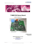
Figure 2.
STEVAL-ILL029V2 demonstration board front view
Figure 3.
STEVAL-ILL029V2 demonstration board rear view
Figure 4.
6/34
STEVAL-CBP007V1 front view
Doc ID 010039 Rev 1
UM1058
Hardware description
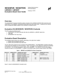
Figure 5.
STEVAL-CBP007V1 rear view
Figure 6.
STLED325 board with STEVAL-CBP007V1
Major components present on STEVAL-ILL029V2 board are (refer to Figure 2 and 3):
●
8 front panel keys (1): CH+, CH-, BRGHT+, BRGHT-, STBY, MENU, OK, DEMO
●
8 front panel keys (5): CH+, CH-, BRGHT+, BRGHT-, STBY, MENU, OK, DEMO
●
BRGHT_ADJ potentiometer (9)
●
PWR/STBY LED (7)
●
Interrupt LED (16)
●
MUTE LED (8)
●
External Host Interface connector (13)
●
DIP switch(12)
●
SWIM connector (14)
●
IR sensor (17)
●
STM8S207K6T6 microcontroller(2)
●
7-segment (+dot) display (3)
●
STLED325(1)
●
32.768 kHz RTC crystal(15)
●
8 discrete LEDs for brightness(4)
Doc ID 010039 Rev 1
7/34
Hardware description
UM1058
●
Wake-up key (6)
●
DC buzzer for alarm function(19)
●
Super cap for backup (21) (battery can also be used as an alternative to super cap)
●
System reset switch (20)
●
DC power jack (18)
Major components present on STEVAL-CBP007V2 are (refer Figure 4 and 5):
2.1
●
STMPE24M31QTR (3)
●
Connectors to interface STEVAL-CBP007V1 with STEVAL-ILL029V2 (4, 5)
●
8 touchkeys for individual functions, 8-channel rotator for brightness control (1,2)
Power supply unit
The board is equipped with a DC jack, shown in Figure 7, into which an external adaptor (9
V-18 V, 500 mA) can be plugged. The board consists of a 5 V output switching regulator for
higher efficiency and a 3.3 V output linear regulator onboard to give regulated outputs, as
required. The board may also be powered up using a PC laptop adaptor. The user must
ensure that the external PSU jack is of the center positive type, although reverse polarity
does not damage the demonstration board. A bicolor “PWR/STBY” LED (D4), shown in
Figure 2, signifies the presence of supply on the board. When in normal operation the
PWR/STBY LED is green and turns red when the system is in standby condition.
Figure 7.
8/34
DC power jack
Doc ID 010039 Rev 1
UM1058
2.2
Hardware description
7-segment (+decimal point) and discrete LED display
The board consists of 4 7-segment (+decimal point) display modules driven by STLED325.
By default, the left two digits display the channel information while the right two display the
brightness level information.
2.3
Figure 8.
7-segment LED display
Figure 9.
Discrete LEDs
Front panel keys / wake-up mechanical keys
STEVAL-ILL029V2 is provided with 8 front panel keys: CH+, CH-, BRGHT+, BRGHT-, OK,
MENU, DEMO and STBY. There is one wake-up designated as WAKE-UP to wake up the
system from standby.
Doc ID 010039 Rev 1
9/34
Hardware description
2.4
UM1058
DIP switch / external interface connector
STEVAL-ILL029V2 consists of an 8-position DIP switch (SW2). All the switches should be in
the ON position (towards circle/ON side) for the demo to work. When the device STLED325
is required to be isolated from the onboard STM8S host and controlled through an external
I2C host, all the switches should be moved to the OFF position. Then, STLED325 control
pins can be accessed through an external interface connector (J3). A detailed description of
the external interface connector is provided on the bottom silkscreen of the board and also
listed below for reference:
Figure 10. External interface connector
*
)#?3$!
34"9
)21?.
-?).4
6
'.$
)#?3#,
2%!$9
).42?,%$
-2%3%4
6
'.$
!-V
2.5
IR sensor connector
A 38 kHz IR sensor is mounted at J4 for IR control and supports RC5 protocol.
2.6
Interrupt LED
There is a blue interrupt LED (D21: INTR) which blinks whenever an interrupt is asserted
from the STLD325 device, which may be due to front panel key press, remote control key
press, RTC alarm, wake-up from standby, etc.
2.7
Interface connectors
Please refer to (10, 11) Figure 2, STEVAL-ILL029V2 consists of touch board interface
connectors (J6, J7) on which the STMPE24M31 touch board can be mounted. STEVALCBP007V1 also consists of two interface connectors J1, J2 refer to (4, 5) Figure 4. J1 on the
touch board connects with J6 on the STLED325 board while J2 on the touch board connects
with J7 on the STLED325 board.
2.8
Touch pads / 8-channel touch status type rotator
STEVAL-CBP007V1 consists of 8 touch pads for individual functions such as BRIGHT-,
BRIGHT+, CH+, CH-, OK, DEMO, STANDBY, and MENU. Figure 4 (2) refers to the touch
status type 8-channel rotator for brightness increase/decrease.
10/34
Doc ID 010039 Rev 1
UM1058
Getting started
3
Getting started
3.1
Package content
The STLED325 front panel with STMPE24M31 interface demonstration board package
includes:
3.2
●
STLED325 demonstration board (STEVAL-ILL029V2)
●
STMPE24M31 touch panel card (STEVAL-CBP007V1)
●
UM1058 user manual (this document)
●
Schematics
●
Gerber files
System requirements
The STEVAL-CBP007V1 board needs to be interfaced to the STEVAL-ILL029V2 host board
in such a way that connector J1, J2 (on touch board) connects with connectors J6, J7 (on
host board). The system operates by powering externally through an external adaptor (9 V18 V, 500 mA). The board can also be powered up using a laptop adaptor.
3.3
Powering on the system
As soon as DC power supply is plugged in, the system is up and running. PWR/STBY LED
(D4) is green with MUTE LED (D3) turned off.
3.4
Startup display sequence / default setting of the system
On startup the system displays a rotating text welcome message on the 7-segment display.
If the touch board is present, the message is “STLED325-STMPE24M31”; otherwise it
displays “STLED325”. Then, “c h b r” is displayed for about 2 seconds, after which the
system displays the channel number and brightness level information. When the board is
powered on for the first time, the following default settings are programmed:
–
Channel number: 00
–
Brightness information: 01 (01/16)
Subsequently, every time the board is powered on, it retains the last configured data and
displays the same on startup. The STM8S internal EEPROM is used to store the user data
(channel number and brightness information), and this feature is not available if an external
host is used.
Doc ID 010039 Rev 1
11/34
System features (touch board connected)
4
UM1058
System features (touch board connected)
Connect the STEVAL-CBP007V1 board to STEVAL-ILL029V2 with connectors J1 (5-pin)
and J2 (4-pin) on the touch board, mating with the female connectors J6 (5-pin) and J7 (4pin), on the host board. It is important that the touch board is mounted with proper
orientation before the system is powered on.
On powering on the system, a rotating text message “STLED325-STMPE24M31” is
displayed on the 7-segment display. After this, channel-brightness information is displayed
followed by blinking, one time, of all LEDs present on the touch board. After this sequence is
over, the system is ready for operation. There are a total of 7 LEDs at the bottom of the
individual keys: BRIGHT+, BRIGHT-, CH+, CH-, OK, DEMO, and MENU. Touch of any of
these keys is indicated by blinking of the corresponding LED as well as a buzzer sound.
4.1
Channel number - brightness level display mode
In this mode the system displays the channel number (on the leftmost two 7-segment
display modules) and brightness level (on the rightmost two displays). Channel number and
brightness can be increased/decreased using the touchkeys provided on the board (CH+,
CH-, BRIGHT+, and BRIGHT-).
A similar operation can be performed using the remote control keys explained in
Section 4.4.
Maximum and minimum limits for the channel number are 99 and 00 while the maximum
and minimum values for brightness level are 16 and 1 (16/16, 1/16).
Brightness level is also shown by the number of discrete LEDs glowing. (1 LED each for 2
levels). Brightness level can also be increased/decreased using the 8-channel touch status
type rotator present on the board. The brightness increases on clockwise rotation and
decreases for anticlockwise rotation.
In one complete rotation, the brightness changes by 16 levels.
4.2
RTC operation
STLED325 also features an inbuilt RTC. A MENU key on the touch board is provided to
select RTC set/view options. Various touchkeys can be used to operate the real time clock.
Use the MENU touchkey to enter into menu options and navigate through them. Touch the
MENU once - “rtc' is displayed. Now touch OK to enter into RTC options. By using the
MENU key the user can navigate through:
“TIME” (view time), “DATE” (view date), “SETT”(set time), “SETD”(set date), “SETA”(set
alarm).
4.2.1
Display time
Choose MENU to go to “rtc” and then OK. “tIME” is displayed. Now choose OK again to go
to view time. “HH.MM” is displayed for a second to signify time display in Hours-Minutes
format, followed by current RTC time display with hours and minutes separated by a “.”.
Choose OK again to exit to the channel-brightness display.
12/34
Doc ID 010039 Rev 1
UM1058
4.2.2
System features (touch board connected)
Display date
Choose MENU and then OK. Now use the MENU touchkey again to reach “dAtE” and
choose the OK key. “DD.MM” is displayed for a second to signify date display in date-month
format, after which, the current RTC date is displayed. Date and month data are separated
by a “.”. Choose OK again to exit to the channel-brightness display.
4.2.3
Set time
Choose MENU, and then OK. Use the MENU key to go to “SETT”. Now choose OK. The
system prompts to enter the time in “Hours-Minutes” format. Use front panel keys BRGHT+
and BRGHT- to increase and decrease the value and CH- and CH+ to move left/right. The
seconds field is taken as 0.
After adjusting the time, choose OK. The time is set and the display returns to channelbrightness display.
4.2.4
Set date
Choose MENU, and then OK. Choose MENU again multiple times to go to “SETD”. Now
choose OK. The system prompts to enter the date in “Date-Month” format. Use touchkeys
BRIGHT+ and BRIGHT- to increase and decrease the value and CH- and CH+ to move
left/right. After adjusting the date, choose OK again. Now the system prompts to enter the
year (two digits “e.g 10 for 2010 and week day (1-Monday…..7-Sunday). After entering the
information, choose OK. The date is set and the system returns to channel-brightness
display.
4.2.5
Set alarm
Choose MENU, and then OK. Choose MENU again multiple times to go to “SETA”. Now
choose OK. The system shows the current RTC time and prompts to enter the alarm time in
“Hours-Minutes” format. Use front panel keys BRIGHT+ and BRIGHT- to increase and
decrease the value and CH- and CH+ to move left/right. The seconds field is taken as 0 and
current RTC date as the alarm date, automatically. After adjusting the value, choose OK
again. The alarm is set and the system returns to channel-brightness display.
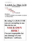
4.2.6
Alarm condition display
When the alarm alert is received from the STLED325 internal RTC, “-AL-” is displayed along
with the buzzer sound (Tick-Tick sound: This buzzer is driven by GPIO1 of STLED325). If
the system is in display RTC mode (display RTC time/RTC date) when the alarm condition is
met, the system display remains at its previous display state (display RTC) during the alarm
while the buzzer still sounds. The alarm goes off when any interrupt is received (touchkey
press/RC key press) and the system returns to channel-brightness display mode.
Doc ID 010039 Rev 1
13/34
System features (touch board connected)
UM1058
Figure 11. Alarm display
4.3
Demo mode
The system enters into demo mode by using the DEMO touchkey on the front panel. In this
mode, scrolling text with varying brightness and increasing scrolling speed is displayed
continuously on the display.
Text displayed: “STLED325-STMPE24M31 Front Panel Demo” followed by blinking of 325
two times (left aligned and right aligned).
The system comes out of demo mode and returns to channel-brightness display when either
any of the touchkeys or RC key is pressed, or RTC alarm condition is met.
4.4
Remote control operation
The system currently supports only RC5 protocol; however, it can be easily adapted to
implement other RC protocols. The MENU options support changing the currently used RC
protocol but are not currently implemented in the system. For more details, refer to the
STLED325 datasheet.
The following RC operations can be done using IR decoding feature of STLED325.
Device address programmed: 0x08
14/34
●
Channel up (key value: 7 and key value: 45)
●
Channel down (key value: 14 and key value: 44)
●
Brightness increase (key value: 8)
●
Brightness decrease (key value: 27)
●
DEMO (key value: 21)
●
STANDBY (key value: 12)
Doc ID 010039 Rev 1
UM1058
System features (touch board connected)
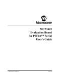
Figure 12. Example RC5 remote
4.5
1.
CH+
2.
CH-
3.
BRGHT+
4.
BRGHT-
5.
CH-
6.
CH+
7.
STANDBY
Standby mode
STLED325 also features standby power management to host. The system can enter into
standby mode by:
1.
Using standby touchkey
2.
Remote control standby key
On entering standby mode, the PWR/STBY LED (D4) turns red. The MUTE LED (D3) also
turns ON. “STBY” is displayed on the LED panel for about two seconds (refer to Figure 13),
after which the complete display is blanked (discrete LEDs also turned off), refer to
Figure 14. If the system is in display RTC mode (time/date display) when the standby key is
pressed, the 7-segment display does not get blanked but displays RTC during standby
mode (discrete LEDs are off). During standby, all the RC keys except the hot keys are nonfunctional.
Doc ID 010039 Rev 1
15/34
System features (touch board connected)
UM1058
Figure 13. Entering into standby
Figure 14. System is in standby
The system can wake up from standby through any of the following modes:
1.
A touch on any of the touchkeys
2.
Remote control hot key press (RC standby key configured as a hot key)
3.
RTC alarm
The system returns to channel-brightness display after wake-up from standby mode.
16/34
Doc ID 010039 Rev 1
UM1058
System features (touch interface not connected)
5
System features (touch interface not connected)
5.1
Brightness adjustment through potentiometer
The system is also provided with a potentiometer “BRGHT_ADJ” (R5) which can be used to
vary the brightness of the LEDs by setting the output current. The brightness increases
when the potentiometer is rotated clockwise and decreases with anticlockwise rotation.
5.2
Channel number - brightness level display mode
In this mode the system displays the channel number (on the leftmost two 7-segment
display modules) and brightness level on the rightmost two displays. Channel number and
brightness can be increased/decreased using the front panel keys provided on the board
(CH+, CH-, BRGHT+, BRGHT-).
A similar operation can be performed using remote control keys as explained in Section 5.5.
Maximum and minimum limits for channel number are 99 and 00 while the maximum and
minimum values for brightness level are 16 and 1 (16/16, 1/16).
Brightness level is also shown by number of discrete LEDs glowing. (1 LED each for 2
levels).
5.3
RTC operation
STLED325 also features an inbuilt RTC. The MENU key on the front panel is provided to
select RTC set/view options. Various front panel keys can be used to operate the real time
clock.
Choose MENU to enter into menu options and navigate through them. Choose MENU once
- “rtc' is displayed. Now press OK to enter into RTC options. Now, using the MENU key the
user can navigate through:
“TIME” (view time), “DATE” (view date), “SETT”(set time), “SETD”(set date), “SETA”(set
alarm).
5.3.1
Display time
Choose MENU to go to “rtc” and then OK. “tIME” is displayed. Now press OK again to go to
view time. “HH.MM” is displayed for a second to signify time display in Hours-Minutes
format, followed by current RTC time display with hours and minutes separated by a “.”.
Choose OK again to exit to the channel-brightness display.
5.3.2
Display date
Choose MENU and then OK. Now use the MENU key again to reach “dAtE” and press OK
key. “DD.MM” is displayed for a second to signify date display in date-month format, after
which the current RTC date is displayed. Date and month data are separated by a “.”.
Choose OK again to exit to the channel-brightness display.
Doc ID 010039 Rev 1
17/34
System features (touch interface not connected)
5.3.3
UM1058
Set time
Choose MENU and then OK. Use the MENU key to go to “SETT”. Now press OK. The
system prompts to enter the time in “Hours-Minutes” format. Use front panel keys BRGHT+
and BRGHT- to increase and decrease the value and CH- and CH+ to move left/right. The
seconds field is taken as 0.
After adjusting the time, press OK. The time is set and the display returns to channelbrightness display.
5.3.4
Set date
Choose MENU and then OK. Choose MENU again multiple times to go to “SETD”. Now
press OK. The system prompts to enter the date in “Date-Month” format. Use front panel
keys Bright+ and Bright- to increase and decrease the value and CH- and CH+ to move
left/right. After adjusting the date, choose OK again. Now the system prompts to enter the
year (two digits “e.g 10 for 2010 and week day (1-Monday…..7-Sunday). After entering the
information, press OK. The date is set and the system returns to channel-brightness display.
5.3.5
Set alarm
Choose MENU and then OK. Choose MENU again multiple times to go to “SETA”. Now
press OK. The system shows the current RTC time and prompts to enter the alarm time in
“Hours-Minutes” format. Use front panel keys Bright+ and Bright- to increase and decrease
the value and CH- and CH+ to move left/right. The seconds field is taken as 0 and current
RTC date as alarm date automatically. After adjusting the value, press OK again. The alarm
is set and the system returns to channel-brightness display.
5.3.6
Alarm condition display
When the alarm alert is received from the STLED325 internal RTC, “-AL-” is displayed along
with the buzzer sound (Tick-Tick sound: this buzzer is driven by GPIO1 of STLED325). If the
system is in display RTC mode (display RTC time/RTC date) when the alarm condition is
met, the system display remains at its previous display state (display RTC) during the alarm
while the buzzer still sounds. The alarm goes off when any interrupt is received (FP key
press/RC key press) and the system returns to channel-brightness display mode.
5.4
Demo mode
The system enters into demo mode by pressing the DEMO key on the front panel. In this
mode, scrolling text with varying brightness and increasing scrolling speed is displayed
continuously on the display.
Text displayed: “STLED325 Front Panel Demo” followed by blinking of 325 two times (left
aligned and right aligned).
The system comes out of demo mode and returns to channel-brightness display when either
any of the front panel or RC key is pressed or the RTC alarm condition is met.
5.5
Remote control operation
The remote control operation remains the same as mentioned in Section 4.4.
18/34
Doc ID 010039 Rev 1
UM1058
5.6
System features (touch interface not connected)
Standby mode / hot keys
Standby operation remains the same as that mentioned in Section 4.5 except that the
system can enter into standby by:
●
Pressing the front panel standby key
●
Remote control standby key
During standby, all the front panel and RC keys except the hot keys are non-functional.
The system can wake up from standby by any of the following modes:
●
Wake-up key press
●
Front panel hot key press (STBY and OK are configured as hot keys)
●
Remote control hot key press (RC standby key configured as a hot key)
●
RTC alarm
The system returns to channel-brightness display after wake-up from standby mode.
Doc ID 010039 Rev 1
19/34
20/34
Doc ID 010039 Rev 1
5
N
4
675
5
N
9
&
X)
',*
',*
',*
',*
',*
087(/('
'
087(
9
67/('
.(<
.(<
9&&
',*
',*
',*
',*
',*
9
*3,2
087(
,54B1
*3,2
*3,2
,5B,1
6'$
6&/
:$.(83
8
,6(7
9%$7
95(*
*1'
;,1
;287
67%<
5($'<
73
5
N
5
5
9
.(<
.(<
6(*.6
6(*.6
6(*.6
6(*.6
6(*.6
6(*.6
6(*.6
6(*.6
327B9$5
5
&
Q)
95(*
,&B6'$
,&B6&/
%$7-
5
N
5
N
5
9
9
5
5
9
9
5
5
&
)
5
N
5
N
,54B1
95(*
,54B1/('
'
5
5
9
5'212702817
9
(,7+(52)>55@25>55@72%(02817('
6(*.6
6(*.6
6(*.6
6(*.6
6(*.6
6(*.6
6(*.6
6(*.6
9
'
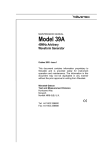
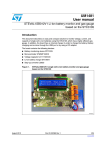
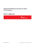
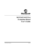
STEVAL-ILL029V2 schematics
,5B,1
,&B6'$
,&B6&/
:$.(B83
087(
,54B1
5
N
5
N
*1'
26&BB,1
26&B287
67%<
5($'<
5
N
5
N
9
9
&
X)
9
*1'
6.1
5
N
*3,2B%8==
9
&
S)
26&BB,1
9
9
Schematics
%8==(5
%=
&
S)
26&B287
<
.+]
9
6
&
Q)
Schematics
UM1058
Figure 15. STLED325 section
.(<
.(<
!-V
Doc ID 010039 Rev 1
-
9
5
9
&
Q)
5
5
.
6706.7&
1567
26&
2&6
9VV
9&$3
9''
9'',2B
3)
9''$
966$
,&B6'$3%
,&B6&/3%
3%
3%
3%
3%
8
67%<
3'
3'
3'
3'
3'
3'
3'
3'
3&
3&
3&
3&
3&
3&
3&
3(
'
5
.
5
.
3'B86$57B5;
3'B86$57B7;
6:,0
3&B0B,17
3&B0B5(6(7
3&B,175
3(B,175B/('
4
675
9
9
5
.
5
.
9
5
.
%,&2/25B60'/('
:$.(B83
6:
*1'
*1'
3%B,&B6'$ 3%B,&B6&/ 3%B67%<
3%B5($'< :$.(B83
5
N
&
Q)
9
'
,175/('
&
X)9
&
Q)
&
Q)
1567
6:,0
*1'
1567
,175B/('
6:
5(6(7
5
N
6:,0B&211
9
&21
-
UM1058
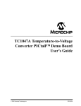
Schematics
Figure 16. Microcontroller section
!-V
21/34
Schematics
UM1058
Figure 17. Keyscan circuit
6:
%5,*+7
.(<
'
6:
%5,*+7
.(<
%$7-
6:
&+
.(<
'
6:
&+
.(<
%$7-
6:
2.
.(<
'
6:
0(18
.(<
%$7-
6:
'(02
.(<
'
6:
67%<
.(<
%$7-
6(*.6
6(*.6
6(*.6
6(*.6
!-V
Figure 18. Connectors
6:
3%B,&B6'$
3%B,&B6&/
3%B67%<
3%B5($'<
3&B,175
3(B,175B/('
3&B0B,17
3&B0B5(6(7
,&B6'$
,&B6&/
67%<
5($'<
,54B1
,175B/('
0B,17
0B5(6(7
6:',3
-
,&B6&/
5($'<
,175B/('
0B5(6(7
9
-
,5B,1
9
5
&21B,56(1625
,&B6'$
67%<
,54B1
0B,17
9
&
X)
&21
&
S)
%84%2.!,(/34).4%2&!#%
-
,&B6'$
,&B6&/
0B,17
9
-
9
9
0B5(6(7
*1'
&21
&21
!-V
22/34
Doc ID 010039 Rev 1
UM1058
Schematics
Figure 19. Power supply section
95(*8/$725
'
677+
9
8
9
&
Q)
&
X)
5
'
6736/$
-
9,
92
&
Q)
*1'
9,1+ %<3$66
&
X)
&
Q)
/'605
95(*8/$725
8
95(*8/$725
/
/
9
X+
&
Q)
'
677+
9
8
&
X)
5
N
9
'
6736/$
5
N
&
Q)
9,
9RXW
&
Q)
%227
*1'
66B,1+
&
X)9
287
&203
&
Q)
26&
&
Q)
)%
9&&
9
&
X)
*1'
5
N
9
&
Q)
/'6$6 75
5
N
&
Q)
!-V
Figure 20. Discrete LED
',*
5
'
/('
5
'
/('
5
6(*.6
5
'
/('
5
6(*.6
'
/('
6(*.6
6(*.6
'
/('
5
6(*.6
5
5
6(*.6
'
/('
6(*.6
'
/('
6(*.6
'
/('
!-V
Doc ID 010039 Rev 1
23/34
Schematics
UM1058
Figure 21. Seven segment LED
5
5
3%'+3
3%'+3
$)'
3%'+3
3%'+3
3%'%
3%'$
#!
3%'#
3%''
3%'&
#!
3%'!
3%'$P 3%'"
3%'+3
3%'+3
3%'+3
3%'+3
$)'
3%'+3
3%'+3
3%'+3
3%'+3
5
3%'+3
$)'
3%'+3
3%'+3
3%''
3%'$
3%'&
3%'#
3%'$
3%'&
#!
3%'#
#!
3%'!
3%'$P 3%'"
3%'+3
3%'+3
3%'+3
3%'+3
3%'+3
3%'+3
5
3%'%
#!
3%''
($30
($30
3%'+3
3%'%
#!
3%'!
3%'$P 3%'"
3%'+3
3%'+3
3%'+3
3%'+3
$)'
3%'+3
3%'+3
3%'+3
3%'+3
($30
3%'%
3%''
3%'$
3%'&
#!
3%'#
#!
3%'!
3%'$P 3%'"
3%'+3
3%'+3
($30
!-V
24/34
Doc ID 010039 Rev 1
Doc ID 010039 Rev 1
&
Q)
&
Q)
&
Q)
6&/
$''5(66B
,17
9&&
&$3B
&$3B
9,2
*1'
*3,2B
*3,2B
&
Q)
*1'B3
*1'B3
6703(0
$''5B
0B,17
9&&
73B527$725
73B527$725
9B0
*1'
7.B/('B%5,*+7
7.B/('B%5,*+7
&
S)
& *1'
S)
,&B6&/B0
*1'
,&B6'$B0
$''5B
0B5(6(7
9B0
7.B/('B&+
7.B/('B&+
*1'
73B527$725
73B527$725
6##!.$6)/#!.6!29&2/- 6
5
9,2
*3,2B
*3,2B
*1'
&$3B
&$3B
&B5()
$''5(66B
5(6(7B1
6'$
*3,2B
*3,2B
*3,2B
*3,2B
9,2
*1'
&$3B
&$3B
*3,2B
*3,2B
*3,2B
*3,2B
*3,2B
*1'
9,2
&$3B
&$3B
*3,2B
*3,2B
*3,2B
9B0
*1'
7.B/('B0(18
7.B/('B'(02
7.B0(18
7.B67$1'%<
9B0
*1'
73B527$725
73B527$725
7.B/('B2.
7.B&+
7.B%5,*+7
7.B2.
*1'
9B0
73B527$725
73B527$725
7.B&+
7.B'(02
7.B%5,*+7
9&&
5
&
Q)
&
X)
&
X)
&
S)
*1'
*1'
0B,17
0B5(6(7
$''5B
$''5B
0B,17
0B5(6(7
$''5B
$''5B
9&&
9&&
*1'
9&&
*1'
5 9B0
N
5 9B0
N
5
.
5 9B0
.
5
N
5
N
5
.
5
.
./4%
-/5.4%)4(%2;2222=
/2;2222=
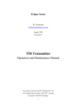
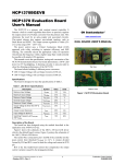
6.2
8
UM1058
Schematics
STEVAL-CBP007V1
Figure 22. STMPE24M31 section
!-V
25/34
Schematics
UM1058
Figure 23. LED section
'
7.B/('B%5,*+7
/('
5
(
/('
5
(
/('
5
(
/('
5
(
/('
5
(
/('
5
(
/('
5
(
'
7.B/('B%5,*+7
'
7.B/('B&+
'
7.B/('B&+
'
7.B/('B0(18
'
7.B/('B'(02
'
7.B/('B2.
!-V
Figure 24. Connectors
-
-
,&B6'$B0
,&B6&/B0
0B,17
9B0
0B5(6(7
*1'
&21
&21
!-V
Figure 25. Touchkeys
&
S)
&
S)
7.B67$1'%<
&
S)
7.B'(02
&
S)
7.B2.
&
S)
7.B0(18
&
S)
7.B&+
&
S)
7.B&+
.(<
.(<
.(<
.(<
.(<
.(<
.(<
728&+3$' 728&+3$' 728&+3$' 728&+3$' 728&+3$' 728&+3$' 728&+3$'
7.B%5,*+7
7.B%5,*+7
.(<
728&+3$'
&
S)
!-V
26/34
Doc ID 010039 Rev 1
UM1058
Schematics
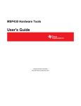
Figure 26. Touchkeys for rotator
527$725
&
S)
73B527$725
&
S)
73B527$725
&
S)
73B527$725
&
S)
73B527$725
&
S)
73B527$725
&
S)
73B527$725
&
S)
73B527$725
73B527$725
3,1B527$725
&
S)
!-V
Doc ID 010039 Rev 1
27/34
Bill of material
7.1
BOM STEVAL-ILL029V2
Table 1.
BOM for STEVAL-ILL029V2
UM1058
7
Doc ID 010039 Rev 1
Reference
designator
Component
description
Package
Manufacturer
Manufacturer’s ordering code /
orderable part number
U1
STM8S 8-bit
microcontroller
LQFP32
STMicroelectronics
STM8S207K6T6C
U2
LED controller/driver
QFN32
STMicroelectronics
STLED325QTR
STMicroelectronics
STLED325QTR
U3
LDS3985M18TR/volta
ge regulator
SOT23-5L
STMicroelectronics
LDS3985M18TR
STMicroelectronics
LDS3985M18TR
U4
L4978
DIP8
STMicroelectronics
L4978
STMicroelectronics
L4978
U5
LD1117AS33TR
SOT-223
STMicroelectronics
LD1117AS33TR
STMicroelectronics
LD1117AS33TR
D1, D5, D6, D7,
D8
BAT54J
SOD323
STMicroelectronics
BAT54JFILM
STMicroelectronics
BAT54JFILM
D9, D20
Schottky diode
SMA
STMicroelectronics
STPS1L30A
STMicroelectronics
STPS1L30A
D10, D11 (Do not
mount)
Diode
SMA
STMicroelectronics
STTH102
STMicroelectronics
STTH102
Q1
PNP transistor
SOT-23
STMicroelectronics
2STR2215
STMicroelectronics
2STR2215
Q2
NPN transistor
SOT-23
STMicroelectronics
2STR1215
STMicroelectronics
2STR1215
Y1
32.768 kHz crystal
Through hole
Vishay/Dale
XT26TTA32K768
MOUSER
73-XT26T
BZ1
Piezoelectric buzzer
Through hole
CUI
CEP-2242
Digi-Key
102-1115-ND
D4
Bicolor PWR/STBY
LED
PLCC-4
Kingbright
KAA-3528ESGC
Farnell
1318239
D2
Interrupt LED (blue)
PLCC2
OSRAM Opto
Semiconductors
Inc
LB T673-L2P1-35-0-10-R18-Z
Digi-Key
475-1387-1-ND
Supplier
Supplier
ordering code
STMicroelectronics STM8S207K6T6C
Bill of material
28/34
BOM for STEVAL-ILL029V2 (continued)
Doc ID 010039 Rev 1
Reference
designator
Component
description
Package
Manufacturer
Manufacturer’s ordering code /
orderable part number
Supplier
Supplier
ordering code
D3
Mute LED (red)
PLCC2
Avago
Technologies US
HSMC-A101-S00J1
Digi-Key
516-2122-2-ND
U6, U7, U8, U9
HDSP5501 common
anode
0.55 inch, 2.5
mm pitch
Avago
Technologies US
Inc.
HDSP-5501
Digi-Key
516-1212-5-ND
SW2
DIP-8 switch
SMT
C&K
SDA08H0SBD
MOUSER
611SDA08H0SBD
SW1, SW3, SW4,
SW5, SW6, SW7,
SW8, SW9,
SW10, SW11
Tactile switches
6.0x6.0x7.0
mm
160 gf
Through hole
ALPS
SKHHBWA010
MOUSER
688-SKHHBW
J1, J4, J6, J7 (J6
and J7 not
mounted)
Single row Bergstrip
2.54 mm pitch
Through hole
Protectron
P9102-40-12-1
Protectron
P9102-40-12-1
J3
Dual row Bergstrip
2.54 mm pitch
Through hole
Protectron
P9103-80-12-1
Protectron
P9103-80-12-1
4-pin female Bergstrip 2.54 mm pitch
header (do not mount) Through hole
Protectron
P9301-36-11
Protectron
P9301-36-11
J4 (Do not mount)
DC jack connector
2.5 mm right
angle locking
type
Protectron
PDCJ01-08
Protectron
PDCJ01-08
L1
100 µH
SMD
Coil-craft
DS5022P-104MLB
Coilcraft
DS5022P104MLB
R1, R9, R13, R18,
R21, R28, R37,
R38
4.7 kΩ
SMD0805
Panasonic - ECG
ERJ-6GEYJ472V or equivalent
Digi-Key
P4.7KATR-ND
R2, R8, R19, R20,
R44, R45
10 kΩ
SMD0805
Panasonic - ECG
ERJ-6GEYJ103V or equivalent
Digi-Key
P10KACT-ND
R3
360 Ω
SMD0805
Panasonic - ECG
ERJ-6GEYJ361V or equivalent
Digi-Key
P360ATR-ND
R4
10 Ω
SMD0805
Panasonic - ECG
ERJ-6GEYJ100V or equivalent
Digi-Key
P10ATR-ND
UM1058
J5
Bill of material
29/34
Table 1.
BOM for STEVAL-ILL029V2 (continued)
Doc ID 010039 Rev 1
Component
description
Package
Manufacturer
Manufacturer’s ordering code /
orderable part number
Supplier
Supplier
ordering code
R16
3.3 kΩ
SMD0805
Panasonic - ECG
ERJ-6GEYJ472V or equivalent
Digi-Key
P3.3KATR-ND
R6, R11, R39,
R40, R41, R42
1 kΩ
SMD0805
Panasonic - ECG
ERJ-6GEYJ102V or equivalent
Digi-Key
P1.0KATR-ND
R7, R10, R12,
R14, R17, R24,
R29, R30, R31,
R32, R33, R34,
R35, R36 (Do not
mount: R10, R14,
R17)
0
SMD0805
Panasonic - ECG
ERJ-6GEY0R00V or equivalent
Digi-Key
P0.0ATR-ND or
equivalent
R15
220 Ω
SMD0805
Panasonic - ECG
ERJ-6GEYJ221V or equivalent
Digi-Key
P220ATR-ND
R22, R23
100 Ω
SMD0805
Panasonic - ECG
ERJ-6GEYJ101V
Digi-Key
P100ATR-ND
R25
20 kΩ
SMD0805
Panasonic - ECG
ERJ-6GEYJ203V or equivalent
Digi-Key
P20KATR-ND
R26
2.7 kΩ
SMD0805
Panasonic - ECG
ERJ-6GEYJ272V or equivalent
Digi-Key
P2.7KATR-ND
R27
9.1 kΩ
SMD0805
Panasonic - ECG
ERJ-6ENF9101V or equivalent
Digi-Key
P9.10KCCT-ND
R43
47 Ω
SMD0805
Panasonic - ECG
ERJ-P06J470V or equivalent
Digi-Key
P47ADCT-ND
C1, C3, C8, C11,
C12, C13, C15,
C23, C24, C25,
C26
100 nF
SMD0805
Panasonic - ECG
or equivalent
ECJ-2VB1E104K or equivalent
Digi-Key
PCC1828CT-ND
C2
1 µF
SMD1206
Panasonic - ECG
ECJ-3YB1C105K or equivalent
Digi-Key
PCC1882CT-ND
C4,C5
25 pF
SMD0805
AVX Corporation
08051A200JAT2A CAP CERM
Digi-Key
478-3735-1-ND
C7
470 nF
SMD0805
Murata Electronics
North America
GRM21BF51E474ZA01L or
equivalent
Digi-Key
490-1730-1-ND
C9, C14, C16,
C18, C27
10 µF
Case A
Vishay/Sprague or
equivalent
293D106X96R3A2TE3 or
equivalent
MOUSER
74293D106X96R3A
2TE3
30/34
Bill of material
Reference
designator
UM1058
Table 1.
BOM for STEVAL-ILL029V2 (continued)
Reference
designator
Doc ID 010039 Rev 1
Component
description
Package
Manufacturer
Manufacturer’s ordering code /
orderable part number
Supplier
Supplier
ordering code
C10
47 µF
Leaded
50volts 47uF
6.3x11 20%
2.5 LS
Nichicon
UPS1H470MED
MOUSER
647UPS1H470MED
C17
10 nF
SMD0805
Panasonic - ECG
ECJ-2VB1H103K
Digi-Key
PCC103BNCT-ND
C19
220 nF
SMD0805
Panasonic - ECG
ECJ-1VB1A224K
Digi-Key
PCC1749CT-ND
C20, C21
220 µF/63 V
Through Hole
Panasonic - ECG
EEU-FM1E221
Digi-Key
P12383-ND
C22
2.7 nF
SMD0805
Panasonic - ECG
ECJ-2VB1H272K
Digi-Key
PCC272BNCT-ND
C28
22 nF
SMD0805
Panasonic - ECG
ECJ-2VB1H223K
Digi-Key
PCC223BGCT-ND
C29
100 pF
SMD0805
Panasonic - ECG
ECJ-2VC1H101J
Digi-Key
PCC101CGCTND
C6
0.22 F Supercap
Cornell Dubilier
EDLSD224H5R5C
Mouser
598EDLSD224H5R5
C
R5
Potentiometer (0 - 1
kΩ)
Through Hole
VISHAY Spectrol
63M-T607-102 or equivalent
Farnell
9608206
IR Sensor
IR sensor (38 kHz)
Through Hole
Vishay
Semiconductors
TSOP31238
Farnell
1469635
Mounting screws
Slotted Pan Head
Screw 4-40 Thread 1”
Long
AEL Hardware
AEL Hardware
Mounting nuts
440 Hex Nut Natural
Nylon(UL94V-2)
Natural Nylon (UL94V2)
AEL Hardware
AEL Hardware
Bill of material
31/34
Table 1.
UM1058
BOM STEVAL-CBP007V1
Table 2.
BOM
UM1058
7.2
Doc ID 010039 Rev 1
Component
Description
Package
Manufacturer
Manufacturer’s ordering
code / Orderable Part
Number
Supplier
Supplier Ordering
Code
U1
24-channel
touch controller
STMPE24M31
QFN40
STMicroelectronics
STMPE24M31QTR
STMicroel
ectronics
STMPE24M31QTR
D1, D2, D3, D4, D5, D6,
D7
Yellow LEDs
SMD 0805
Kingbright Corp
APT2012SYCK
Digi-Key
754-1134-2-ND
J1, J2
Single row
Bergstrip SMD
(4, 5-pin)
2.54 mm pitch
Through hole
Protectron
P9102-40-12-1
Protectron
P9102-40-12-1
R1,R2,R4,R6,R14,R15,R1
6,R17 [Do not mount:
R1,R2,R6,R15]
4.7 kΩ
SMD0805
Panasonic - ECG
ERJ-6GEYJ472V or equivalent
Digi-Key
P4.7KATR-ND
R1, R6
0
SMD0805
Panasonic - ECG
ERJ-6GEY0R00V or
equivalent
Digi-Key
P0.0ATR-ND
R3,R5,R7,R8,R9,R10,R11
220 Ω
SMD0805
Panasonic - ECG
ERJ-6GEYJ221V or equivalent
Digi-Key
P220ATR-ND
R12, R13
100 Ω
SMD0805
Panasonic - ECG
ERJ-6GEYJ101V or equivalent
Digi-Key
P100ATR-ND
C3, C4, C5, C6, C7 [Do not
mount: C4]
100 nF
SMD0805
Murata Electronics
North America
GRM21BR71E104KA01Lor
equivalent
Digi-Key
490-1673-1-ND
C2, C24
1 µF
SMD1206
Murata Electronics
North America
GRM31MF51E105ZA01L or
equivalent
Digi-Key
490-1832-1-ND
C1
12 pF
SMD0805
AVX Corporation
08051A120JAT2A or
equivalent
Digi-Key
478-5011-1-ND
C8,C9,C10,C11,C12,C13,
C14,C15,C16,C17,C18,C1
9,C20,C21,C22,C23 [Do
Not Mount]
2 pF
SMD0805
Murata Electronics
North America
GQM2195C2A2R0CB01D or
equivalent
Digi-Key
490-3588-1-ND
C25, C26
22 pF
SMD0805
Murata Electronics
North America
GRM2195C2A220JZ01D
Digi-Key
490-1591-1-ND
Bill of material
32/34
Reference Designator
UM1058
8
Revision history
Revision history
Table 3.
Document revision history
Date
Revision
04-May-2011
1
Changes
Initial release.
Doc ID 010039 Rev 1
33/34
UM1058
Please Read Carefully:
Information in this document is provided solely in connection with ST products. STMicroelectronics NV and its subsidiaries (“ST”) reserve the
right to make changes, corrections, modifications or improvements, to this document, and the products and services described herein at any
time, without notice.
All ST products are sold pursuant to ST’s terms and conditions of sale.
Purchasers are solely responsible for the choice, selection and use of the ST products and services described herein, and ST assumes no
liability whatsoever relating to the choice, selection or use of the ST products and services described herein.
No license, express or implied, by estoppel or otherwise, to any intellectual property rights is granted under this document. If any part of this
document refers to any third party products or services it shall not be deemed a license grant by ST for the use of such third party products
or services, or any intellectual property contained therein or considered as a warranty covering the use in any manner whatsoever of such
third party products or services or any intellectual property contained therein.
UNLESS OTHERWISE SET FORTH IN ST’S TERMS AND CONDITIONS OF SALE ST DISCLAIMS ANY EXPRESS OR IMPLIED
WARRANTY WITH RESPECT TO THE USE AND/OR SALE OF ST PRODUCTS INCLUDING WITHOUT LIMITATION IMPLIED
WARRANTIES OF MERCHANTABILITY, FITNESS FOR A PARTICULAR PURPOSE (AND THEIR EQUIVALENTS UNDER THE LAWS
OF ANY JURISDICTION), OR INFRINGEMENT OF ANY PATENT, COPYRIGHT OR OTHER INTELLECTUAL PROPERTY RIGHT.
UNLESS EXPRESSLY APPROVED IN WRITING BY AN AUTHORIZED ST REPRESENTATIVE, ST PRODUCTS ARE NOT
RECOMMENDED, AUTHORIZED OR WARRANTED FOR USE IN MILITARY, AIR CRAFT, SPACE, LIFE SAVING, OR LIFE SUSTAINING
APPLICATIONS, NOR IN PRODUCTS OR SYSTEMS WHERE FAILURE OR MALFUNCTION MAY RESULT IN PERSONAL INJURY,
DEATH, OR SEVERE PROPERTY OR ENVIRONMENTAL DAMAGE. ST PRODUCTS WHICH ARE NOT SPECIFIED AS "AUTOMOTIVE
GRADE" MAY ONLY BE USED IN AUTOMOTIVE APPLICATIONS AT USER’S OWN RISK.
Resale of ST products with provisions different from the statements and/or technical features set forth in this document shall immediately void
any warranty granted by ST for the ST product or service described herein and shall not create or extend in any manner whatsoever, any
liability of ST.
ST and the ST logo are trademarks or registered trademarks of ST in various countries.
Information in this document supersedes and replaces all information previously supplied.
The ST logo is a registered trademark of STMicroelectronics. All other names are the property of their respective owners.
© 2011 STMicroelectronics - All rights reserved
STMicroelectronics group of companies
Australia - Belgium - Brazil - Canada - China - Czech Republic - Finland - France - Germany - Hong Kong - India - Israel - Italy - Japan Malaysia - Malta - Morocco - Philippines - Singapore - Spain - Sweden - Switzerland - United Kingdom - United States of America
www.st.com
34/34
Doc ID 010039 Rev 1
Mouser Electronics
Authorized Distributor
Click to View Pricing, Inventory, Delivery & Lifecycle Information:
STMicroelectronics:
STEVAL-ILL029V2