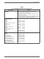
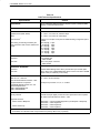
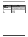
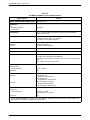
1
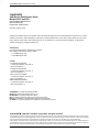
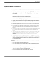
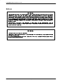
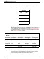
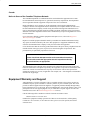
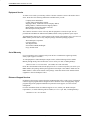
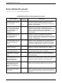
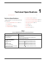
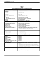
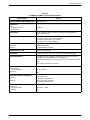
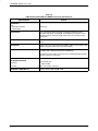
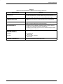
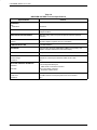
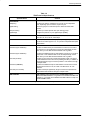
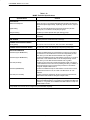
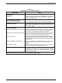
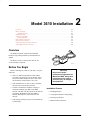
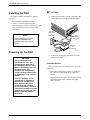
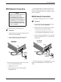
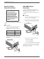
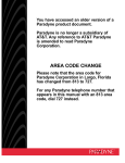
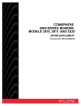
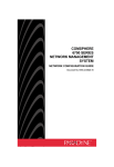
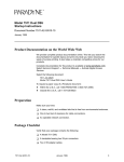
You have accessed an older version of a
Paradyne product document.
Paradyne is no longer a subsidiary of
AT&T. Any reference to AT&T Paradyne
is amended to read Paradyne
Corporation.
AREA CODE CHANGE
Please note that the area code for
Paradyne Corporation in Largo, Florida
has changed from 813 to 727.
For any Paradyne telephone number that
appears in this manual with an 813 area
code, dial 727 instead.
Paradyne
COMSPHERE
3600 Series Data Service Units
Models 3610 and 3611
Documentation Replacement
Document No. 3610-A2-GB43-40
Feature No. 3600-G3-002
COMSPHERE 3600 Series Data Service Units
COMSPHERE
3600 Series Data Service Units
Models 3610 and 3611
Documentation Replacement
3610-A2-GB43-40
Feature No. 3600-G3-002
5th Edition (February 1996)
Changes and enhancements to the product and to the information herein will be documented and issued as a new release.
Address comments to AT&T Paradyne Corporation, Technical Publications, 8545 126th Avenue North, P.O. Box 2826,
Largo, Florida, 34649-2826. AT&T Paradyne may use or distribute any of the information supplied, as appropriate,
without incurring any obligation whatsoever.
United States
FCC Registration number: AW292J-61661-DD-N
PSTN Ringer Equivalence number (REN):
— V.32 DBM option 0.7B
— V.34 DBM option 0.2B
Canada
V.32 Dial Backup Module
Certification number: 230 3684 A
DOC Load number: 7
V.34 Dial Backup Module
Certification number: 230 6811 A
DOC Load number: 3
2-Wire Switched 56 DBM
Certification number: 230 5870 A
DOC Load number: 0
ISDN Dial Backup Module
Certification number: 230 6943 A
DOC Load number: 0
COMSPHERE is a registered trademark of AT&T.
DataPath is a trademark of Northern Telecom, Inc.
DATAPHONE is a registered trademark of AT&T.
MCI is a registered trademark of MCI Communications Corporation.
NetView is a trademark of International Business Machines Corporation.
US SPRINT is a registered trademark of US SPRINT Communications Company.
COPYRIGHT
E 1996 AT&T Paradyne Corporation. All rights reserved.
This publication is protected by federal copyright law. No part of this publication may be copied or distributed, transmitted, transcribed, stored in a retrieval system,
or translated into any human or computer language in any form or by any means, electronic, mechanical, magnetic, manual or otherwise, or disclosed to third parties
without the express written permission of AT&T Paradyne Corporation, 8545 126th Avenue North, P.O. Box 2826, Largo, Florida 34649-2826.
AT&T Paradyne Corporation makes no representation or warranties with respect to the contents hereof and specifically disclaims any implied warranties of
merchantability or fitness for a particular purpose. Further, AT&T Paradyne Corporation reserves the right to revise this publication and to make changes from
time to time in the contents hereof without obligation of AT&T Paradyne Corporation to notify any person of such revision or changes.
A
February 1996
3610-A2-GB43-40
Safety Instructions
Important Safety Instructions
1.
Read and follow all warning notices and instructions marked on the product or included in the
manual.
2.
This product is intended to be used with a three-wire grounding type plug – a plug which has
a grounding pin. This is a safety feature. Equipment grounding is vital to ensure safe
operation. Do not defeat the purpose of the grounding type plug by modifying the plug or
using an adapter.
Prior to installation, use an outlet tester or a voltmeter to check the ac receptacle for the
presence of earth ground. If the receptacle is not properly grounded, the installation must not
continue until a qualified electrician has corrected the problem.
If a three-wire grounding type power source is not available, consult a qualified electrician to
determine another method of grounding the equipment.
3.
Slots and openings in the cabinet are provided for ventilation. To ensure reliable operation of
the product and to protect it from overheating, these slots and openings must not be blocked
or covered.
4.
Do not allow anything to rest on the power cord and do not locate the product where persons
will walk on the power cord.
5.
Do not attempt to service this product yourself, as opening or removing covers may expose
you to dangerous high voltage points or other risks. Refer all servicing to qualified service
personnel.
6.
General purpose cables are provided with this product. Special cables, which may be required
by the regulatory inspection authority for the installation site, are the responsibility of the
customer.
7.
When installed in the final configuration, the product must comply with the applicable Safety
Standards and regulatory requirements of the country in which it is installed. If necessary,
consult with the appropriate regulatory agencies and inspection authorities to ensure
compliance.
8.
A rare phenomenon can create a voltage potential between the earth grounds of two or more
buildings. If products installed in separate buildings are interconnected, the voltage potential
may cause a hazardous condition. Consult a qualified electrical consultant to determine
whether or not this phenomenon exists and, if necessary, implement corrective action prior to
interconnecting the products.
In addition, if the equipment is to be used with telecommunications circuits, take the following
precautions:
–
–
–
–
–
–
3610-A2-GB43-40
Never install telephone wiring during a lightning storm.
Never install telephone jacks in wet locations unless the jack is specifically designed for wet
locations.
Never touch uninsulated telephone wires or terminals unless the telephone line has been
disconnected at the network interface.
Use caution when installing or modifying telephone lines.
Avoid using a telephone (other than a cordless type) during an electrical storm.
There may be a remote risk of electric shock from lightning.
Do not use the telephone to report a gas leak in the vicinity of the leak.
February 1996
B
COMSPHERE 3600 Series Data Service Units
Notices
"
! ! C
February 1996
3610-A2-GB43-40
Safety Instructions
Government Requirements
Certain governments require that instructions pertaining to connection to the telephone network be
included in the installation and operation manual. Specific instructions are listed in the following
sections.
United States
Notice to Users of the Telephone Network
This equipment complies with Part 68 of the FCC rules. On the bottom of the equipment is a label
or silk-screened text that contains, among other information, the FCC registration number and
Ringer Equivalence Number (REN) for this equipment. If requested, please provide this
information to your telephone company.
The REN is useful to determine the quantity of devices you may connect to your telephone line
and still have all of those devices ring when your number is called. In most areas, the sum of the
RENs of all devices should not exceed 5. Call your local telephone company to ascertain the
maximum REN for your calling area.
If your Model 3610 or 3611 DSU with DBM causes harm to the telephone network, the telephone
company may discontinue your service temporarily. If possible, they will notify you in advance.
But if advance notice is not practical, you will be notified as soon as possible. You will be advised
of your right to file a complaint with the FCC.
Your telephone company may make changes in facilities, equipment, operations, or procedures that
could affect the proper operation of your equipment. If so, you will be given advance notice so as
to give you an opportunity to maintain uninterrupted service.
The DBM cannot be used on public coin-operated telephone service provided by the telephone
company. Connection to party-line service is subject to state tariffs. Contact the state public utility
commission, public service commission, or corporation commission for information.
No repairs may be performed by the user. Should you experience difficulty with this equipment,
refer to Equipment Warranty and Support.
3610-A2-GB43-40
February 1996
D
COMSPHERE 3600 Series Data Service Units
For Digital Data Service (DDS) installations, inform the local telephone company of the
appropriate facility interface code for the service you desire.
DDS Facility
Interface
Code
Data Rate
(bps)
04DU5-24
2400
04DU5-48
4800
04DU5-96
9600
04DU5-19
19,200
04DU5-38
38,400
04DU5-56
56,000
04DU5-64
64,000
The DDS Service Order Number is 6.0Y. The jack configurations required are RJ48S for the
Model 3610 DSU and RJ48T for the Model 3611. With the Model 3611 RJ48T configuration, you
must specify the number of data lines you require. Refer to Chapter 1, Technical Specifications.
For DBM installations, the proper service and jack must be ordered from the telephone company.
Refer to the following table for this information.
DBM Jack Installation Requirements
DBM Type
USOC Jack
(Standalone)
USOC Jack
(Carrier-Mounted)
Canadian Jack
(Standalone)
Canadian Jack
(Carrier-Mounted)
12.0 or 14.4 kbps
V.32bis DBM
RJ11C Permissive
RJ45C Programmable
RJ21X Permissive
RJ27X Programmable
CA11A Permissive
CA21A Permissive
CA27A Programmable CA27A Programmable
V.34 DBM
RJ11C Permissive
RJ21X Permissive
CA11A Permissive
CA21A Permissive
2-Wire Switched
56 DBM
SJA48
SJA48 (uses an
adapter cable)
CA11
(metallic channel)
CA21A
(metallic channel)
4-Wire Switched
56 DBM
SJA56
SJA57
Not available
in Canada
Not available
in Canada
ISDN BRI DBM
SJA11
SJA11 (uses an
adapter cable)
CA-A11
CA-A11 (uses an
adapter cable)
After the telephone company has installed the requested service and jack, you can connect the
DSU with the cable provided. An FCC-compliant telephone cord and modular plug are provided
with this equipment. This equipment is designed to be connected to the telephone network or
premises wiring using a compatible modular jack that is Part 68 compliant.
E
February 1996
3610-A2-GB43-40
Safety Instructions
Canada
Notice to Users of the Canadian Telephone Network
The Canadian Department of Communications has certified that this equipment meets certain
telecommunications network protective, operational, and safety requirements. The Department
does not guarantee that the equipment will operate to the user’s satisfaction.
Before installation, verify connectivity of this equipment to the local telecommunications
company’s facilities. The equipment must be connected by an acceptable method. In some cases,
the telecommunications company’s inside wiring associated with single-line individual service
may be extended with a certified connector assembly (telephone connection cord). The customer
should be aware that compliance with the above conditions may not prevent degradation of service
in some situations.
If you experience difficulty with this equipment and require service, refer to the Equipment
Warranty and Support section.
Repairs to certified equipment should be made by an authorized Canadian maintenance facility.
Any repairs or alterations made by the user to this equipment, or equipment malfunctions, may
cause the telecommunications company to ask you to disconnect the equipment.
Users should ensure that the electrical ground connections of the power utility, telephone lines and
internal metallic water pipe system, if present, are connected together for protection. This
precaution may be particularly important in rural areas.
CAUTION
Users should not attempt to make such connections themselves,
but should contact the appropriate electric inspection authority,
or an electrician, as appropriate.
The load number (LN) is labeled on the equipment. The LN denotes the percentage of the total
load to be connected to a telephone loop used by this equipment. To prevent an overload, the total
of the LNs of all devices attached to the loop may not exceed 100. The LN also specifies the
appropriate ringing type (A or B), if applicable. For example, LN = 20A designates a load number
of 20 and an A type ringer.
Equipment Warranty and Support
AT&T Paradyne’s Customer Assistance Center is available 24 hours a day to help you place an
installation request, report a hardware or software problem, or place a trouble report. The center
provides technical support and remote diagnosis of equipment problems Monday through Friday,
between the hours of 8 a.m. and 8 p.m. EST, excluding holidays. You can also call the center if you
participate in the on-site support program or if you would like to request support on a time and
materials basis (refer to the Enhanced Support Services section).
Call the following toll-free number to reach the Customer Assistance Center:
1-800-237-0016 or 1-813-531-4373
Examine the equipment carefully upon arrival. If there is an obvious defect, call the Quality
Careline at 1-813-530-2273, or call 1-800-237-0016, press 0 (zero) for operator, and ask for
extension 2273.
3610-A2-GB43-40
February 1996
F
COMSPHERE 3600 Series Data Service Units
Equipment Service
To obtain service under your warranty, call the Customer Assistance Center at the number listed
above. Please have the following information available before you call:
Company Name and Address
Contact Name and Telephone Number
Shipping Address, if different from the company address
Billing Address, if different than the shipping address
Model Number and Serial Number of the unit
Brief description of the problem
The Customer Assistance Center will verify that the equipment is in need of repair. You are
provided a Return Materials Authorization (RMA) number to help expedite the repair request.
The RMA number must be in a visible location on the outside of the package. Once you receive an
RMA number, pack the unit securely. Ship the package insured and postage prepaid to:
AT&T Paradyne Corporation
Customer Support
Attn: Repair Center
8550 Ulmerton Road, Building B
Largo, Florida 34641
Out of Warranty
If your equipment is out of warranty and you do not have a maintenance support agreement,
factory repair support is available.
To send equipment to AT&T Paradyne’s Repair Center, call the following toll-free number
Monday through Friday, between the hours of 8 a.m. and 5 p.m. EST, excluding holidays:
1-800-772-7691 or 1-813-530-2268 (In Canada, call 1-905-709-5000)
Please have the information listed in the Equipment Service section ready when you call for your
RMA number, then package and ship the equipment to the Repair Center address. Make sure the
RMA number is visible on the outside of the package. A Purchase Order can be mailed with the
equipment or faxed to the Repair Center.
Enhanced Support Services
In addition to the customer support described, AT&T Paradyne offers a wide variety of enhanced
customer support programs that are designed to meet customers needs. Our high quality support
programs range from equipment installation to premium on-site support, as well as network
management.
For more information about our enhanced support services, contact your AT&T Paradyne
representative, or call the following toll-free number, 8 a.m. to 5 p.m. EST, excluding holidays:
1-800-482-333 or 1-813-530-8623
G
February 1996
3610-A2-GB43-40
Preface
Objective
Reference Documents
• ANSI X3.64 – 1979 (Reaffirmed 1990)
To better serve volume Model 3610 DSU customers,
AT&T Paradyne has provided this replacement
documentation so that customers can order only the
number of User’s Guides or Supplements wanted while
permitting us to fulfill our legal and regulatory
requirements.
• ANSI T.410
• AT&T Technical Reference 41458
• AT&T Technical Reference 61330
• AT&T Technical Reference 62310 – 1987
• Document No. 3610-A2-GB46 ships with every
Model 3610 DSU.
• Bell Canada DCTE Specifications
• Document No. 3610-A2-GB48 ships with every
TDM or MCMP.
• Bell Communications Research Technical
Reference Publication 41028
• Document No. 3610-A2-GB49 ships with every
DBM.
• Bellcore Special Report SR-NWT-001953
• DATAPHONE II 2600 Series Data Service Units
User’s Manual
Please refer to the COMSPHERE 3600 Series Data
Service Units (DSUs), Models 3610 and 3611, User’s
Guide, Document No. 3610-A2-GB46, when operating
the DSU.
• EIA-232-D/V.24 (ISO 2110)
• Integrated Network Corporation Compatibility
Bulletin CB-INC-101
• ITU-TSS (CCITT) V.35 (ISO 2593)
Contents
• Northern Telecom NIS S204-2e 1986
Chapter 1 lists the technical specifications for the DSU,
Dial Backup Modules (DBMs), Time Division
Multiplexer (TDM), Multichannel Multipoint (MCMP)
and the digital bridge options.
Chapter 2 describes electrical connection of the
Model 3610 DSU, as well as Digital Data Service (DDS),
Switched 56 kbps, dial, and ISDN networks.
• Pacific Bell PUB L-780035-PB/NB
• Pacific Bell PUB L-780036-PB/NB
Document Ordering
To order AT&T Paradyne documentation, please call
1-800-545-2354, extension 2222 or 1-813-530-8777.
To order AT&T documentation, please call
1-800-432-6600 or 1-317-322-6572.
3610-A2-GB43-40
February 1996
i
COMSPHERE 3600 Data Service Units
Product-Related Documents
The following table lists 3600-related documentation.
COMSPHERE 3600 Series Product-Related Documentation
Document Name
Document
Number
Description
COMSPHERE 3600 Series Data
Service Units, Models 3610 and
3611, User’s Guide
3610-A2-GB46
User’s Guide. Ships with all standalone 3610 DSUs. Provides
descriptions of features, installation instructions, front panel
operation, configuration options and worksheets, troubleshooting,
messages, and specifications.
COMSPHERE 3600 Series Data
Service Units, Models 3610 and
3611, Time Division Multiplexer,
Multichannel Multipoint, and
Digital Bridge Options
Supplement
3610-A2-GB48
Supplement to the User’s Guide. Ships with all standalone
3610 DSUs with TDM, MCMP, or Digital Bridge options or
upgrades. Provides descriptions of TDM, MCMP, and Digital Bridge
features, installation instructions, front panel operation,
configuration options and worksheets, troubleshooting, messages,
and specifications.
COMSPHERE 3600 Series Data
Service Units, Models 3610 and
3611, Dial Backup Module
Options Supplement
3610-A2-GB49
Supplement to the User’s Guide. Ships with all standalone
3610 DSUs with Dial Backup Modules or upgrades. Provides
descriptions of DBMs, features, installation instructions, front panel
operation, configuration options and worksheets, troubleshooting,
messages, and specifications.
COMSPHERE 3600 Series Data
Service Units, Models 3610 and
3611, Technical Reference
Manual
3610-A2-GH30
Orderable. Provides detailed information on the DSU, DBM, SNA
Diagnostic Interface, TDM, MCMP, and Digital Bridge features,
specifications, configuration scenarios, async terminal operation,
pin assignments, NMS operations, messages, and an equipment
list.
COMSPHERE 3600 DBM Option
Installation Instructions
3610-A2-GZ52
Ships with field-installable dial backup upgrades. Contains
installation procedures for all Model 3610 and 3611 DBM types.
COMSPHERE 3000 Series
Carrier, Installation Manual
3000-A2-GA31
Ships with every carrier. Contains installation procedures for the
carrier and its components, options, and operation.
COMSPHERE – 48 Vdc Central
Office Power Unit, Installation
Guide
3000-A2-GB41
Ships with every – 48 Vdc power unit. Includes descriptions of
features, installation instructions, troubleshooting, specifications,
and an equipment list.
COMSPHERE 3600 Series Data
Services Units, Models 3610 and
3611, Secondary Channel
Applications Supplement
3610-A2-GB42
Orderable. Provides details on DSUs equipped with the Secondary
Channel option. Provides descriptions of features, DSU operation,
configuration examples, worksheets, and an equipment list.
COMSPHERE 6800 Series
Network Management System,
Communications Products
Support, Command Reference
Manual
6800-A2-GB31
Ships with software. Provides descriptions of device commands for
interaction between 6800 Series NMS and other product lines.
COMSPHERE 6700 Series
Network Management System,
User’s Guide
6700-A2-GY31
Ships with software and is orderable. Provides descriptions of NMS
features, installation instructions, configuration setup, display and
statistics options, reports generation, online help conventions, and
input forms.
ii
February 1996
3610-A2-GB43-40
Technical Specifications
1
Technical Specifications . . . . . . . . . . . . . . . . . . . . . . . . . . . . . . . . . . . . . . . . . . . . . . . . . . . . . . . . . . . . . . 1-1
• V.34 DBM and DBM-F (Table 1-5)
Technical Specifications
Tables 1-1 through 1-11 list the technical specifications
for the following:
• 2-Wire Switched 56 DBM and DBM-D (Table 1-6)
• 4-Wire Switched 56 DBM and DBM-S (Table 1-7)
• General COMSPHEREr 3600 Series (Table 1-1)
• ISDN DBM and DBM-I (Table 1-8)
• DSU (Table 1-2)
• TDM (Table 1-9)
• 3600 Hubbing Device (Table 1-3)
• MCMP (Table 1-10)
• V.32 DBM and DBM-V (Table 1-4)
• Digital Bridge (Table 1-11)
Table 1-1
(1 of 3)
General COMSPHERE 3600 Series Technical Specifications
Criteria
Specifications
AC POWER FUSE
Model 3610/3611 DSU
No accessible fuse
3000 Series Carrier
4-amp fuse, AT&T Paradyne part number 190-0037-0431
(two spares supplied with carrier)
AC POWER REQUIREMENTS
3610 DSU
3610 DSU with DBM
24 Vac (CT), 60 Hz +3 (0.093 amp, 5.8 watts at 115 Vac)
24 Vac (CT), 60 Hz +3 (0.114 amp, 9.5 watts at 115 Vac)
3611 DSU
3611 DSU with DBM
24 Vac (CT), 60 Hz +3 (0.029 amp, 4.5 watts at 115 Vac)
24 Vac (CT), 60 Hz +3 (0.080 amp, 8.0 watts at 115 Vac)
DBM (V.32 or Switched 56)
24 Vac (CT), 60 Hz +3 (0.024 amp, 2.0 watts at 115 Vac)
3000 Series Carrier (16 DSUs with DBMs
plus SDU and fan module)
90 —132 Vac, 60 Hz +3 (1.650 amp, 165 watts at 115 Vac)
3610-A2-GB43-40
February 1996
1-1
COMSPHERE 3600 Data Service Units
Table 1-1
(2 of 3)
General COMSPHERE 3600 Series Technical Specifications
Specifications
APPROVALS
FCC Part 15
FCC Part 68
Criteria
Class A digital device
AW292J-61661-DD-N
UL
3610 DSU
3611 DSU, 3000 Series Carrier
CSA
Safety
3610 DSU
3611 DSU, 3000 Series Carrier
Emissions
Listed UL 1950
Recognized Component UL 1950
Certified CSA 22.2, No. 220-M1986
Certified Component CSA 22.2, No. 950-M89
Class A digital apparatus
Bell Canada
“DCTE Specifications,” July 1989, Issue 1
DTE INTERFACE
3610 and Non-modular 3611 DSUs
25-pin D-subminiature connector
34-pin connector
EIA-232-D / ITU (CCITT) V.24 (ISO 2110)
ITU (CCITT) V.35 (ISO 2593)
Modular 3611 DSU
25-Pin V.35 Interface
EIA-232-D / ITU (CCITT) V.24 (ISO 2110)
ITU (CCITT) V.35 (ISO 2593)
Uses a Rear Connector Plate with two
25-pin D-subminiature connectors
A modular DSU V.35 interconnect cable is required to use the V.35
connector. The cable provides an interface between the DSU’s 25-pin
D-type connector and the DTE cable’s V.35 connector.
ENVIRONMENT
Operating Temperature
32° to 122° F (0° to 50° C)
Storage Temperature
– 4° to 158° F (–20° to 70° C)
Relative Humidity
5% — 95% (noncondensing)
Shock and Vibration
Withstands normal shipping and handling
HEAT DISSIPATION (MAX.) AT 115 VAC
3610 DSU
3610 DSU with DBM
22.16 Btu/hr.
29.00 Btu/hr.
3611 DSU
3611 DSU with DBM
22.16 Btu/hr.
27.30 Btu/hr.
3000 Series Carrier (16 DSUs with DBMs
plus SDU and fan module)
563.00 Btu/hr.
NMS COMPATIBILITY
DATAPHONE II System Controller, Diagnostic Console, or Network
Controller
COMSPHERE 6700 Series NMS, Release 4.0 or greater for full support
COMSPHERE 6800 Series NMS, Release 4.1.5 or greater for full support
t
NetView , Version 1, Release 3 or greater
ASYNC TERMINAL
ANSI X3.64/VT-100 compatibility
Rate: 9.6 kbps
8 bits per character, 1 stop bit, no parity
1-2
February 1996
3610-A2-GB43-40
Technical Specifications
Table 1-1
(3 of 3)
General COMSPHERE 3600 Series Technical Specifications
Specifications
DATA RATES
Criteria
Primary channel rates: 64, 56, 38.4, 19.2, 9.6, 4.8, and 2.4 kbps
Async/Sync rates: 64, 56, 48, 38.4, 32, 19.2, 18.8, 18.0, 16.8, 14.4, 12.0,
9.6, 9.2, 7.2, 4.8, 4.4, 2.4, 2.0, and 1.2 kbps
Other asynchronous rates (e.g., 150, 300, 600, and 1800 bps) can be
obtained through oversampling
Asynchronous rates support ITU (CCITT) V.14 extended rate range at
8 to 12 bits per character, including the start and stop bit (+2.3, –2.5 percent
overspeed/underspeed compensation at 10 bits per character)
PHYSICAL DIMENSIONS
3610 DSU
Height
Width
Depth
2.13 inches
(5.4 cm)
7.63 inches (19.4 cm)
12.13 inches (30.8 cm)
3611 DSU (non-modular or modular)
Height
Width (thickness)
Depth
7.13 inches (18.1 cm)
0.90 inch
(2.3 cm)
13.40 inches (34.0 cm)
Rear Connector Plate (2-port)
Height
Width
Depth (25-Pin V.35 Interface)
5.24 inches
0.88 inch
1.00 inch
3000 Series Carrier
Height
Width
Depth
10.50 inches (26.7 cm)
19.00 inches (48.3 cm)
14.00 inches (35.6 cm)
(13.3 cm)
(2.2 cm)
(2.5 cm)
WEIGHT
3610 DSU
3610 DSU with DBM
3.70 pounds (1.68 kg)
4.10 pounds (1.86 kg)
3611 DSU (modular)
3611 DSU (modular) with DBM
0.91 pound (0.41 kg)
1.34 pounds (0.61 kg)
3611 DSU (non-modular)
3611 DSU (non-modular) with DBM
1.05 pounds (0.48 kg)
1.50 pounds (0.68 kg)
Rear Connector Plate (2-port)
25-Pin EIA-232/25-Pin V.35
0.13 pound (0.06 kg)
3000 Series Carrier (16 DSUs with
DBMs plus SDU and fan module)
3610-A2-GB43-40
70.00 pounds (31.8 kg)
February 1996
1-3
COMSPHERE 3600 Data Service Units
Table 1-2
DSU Technical Specifications
Criteria
Specifications
APPLICATION
Full- or half-duplex data transmission via point-to-point or multipoint DDS
network, or local area data channel
COMMUNICATION LINE
Leased or private 4-wire DDS line
DATA RATES
Digital Services (DDS, ASDS)
2.4, 4.8, 9.6, 19.2, 38.4, 56, and 64CC kbps
LADS
2.4, 4.8, 9.6, 19.2, 38.4, 56, and 64 kbps
Clear Channel 1
64 kbps (on a 72 kbps circuit) with the 64KScrambling configuration option
enabled
When timing is external (provided by the
DTE), the DTE’s clock must be within these
ranges.
64CC
56
38.4
19.2
9.6
4.8
2.4
kbps
kbps
kbps
kbps
kbps
kbps
kbps
" 11 bps
" 9 bps
" 4 bps
" 5 bps
" 1 bps
" 0 bps
" 0 bps
DDS NETWORK INTERFACE
3610 DSU
3611 DSU
8-pin modular jack
USOC RJ48S
(One or two) 50-pin connector
USOC RJ48T
DIAGNOSTIC INTERFACE
3610 DSU
Requires 3600 Hubbing Device which provides two 8-pin modular jacks
3611 DSU
Via the SDU in the COMSPHERE 3000 Series Carrier or DC-OUT via NMS
adapter cable (for a tributary in the carrier)
NETWORK COMPATIBILITY
ANSI T1.410 – 1992 and
AT&T Technical Reference 62310 – 1987
2.4, 4.8, 9.6, 56, and 64 kbps
Integrated Network Corporation
Compatibility Bulletin CB-INC-101, and
Pacific Bell publications
PUB L-780035-PB/NB and
PUB L-780036-PB/NB
19.2 kbps loop at levels of + 6, 0, or –10 dBm
DSU COMPATIBILITY
Primary Channel
Diagnostic Channel
Point-to-Point or Multipoint:
Point-to-Point Only:
1
1-4
All AT&T Paradyne digital products and other products that are compliant
with AT&T Technical Reference 62310 – 1987
3600 Series — enhanced 3600 diagnostics (nondisruptive or disruptive)
3500 Series — 2600 diagnostics
2600 Series — 2600 diagnostics
2500 Series — 2500 loopbacks
If a 3600 Series DSU is not used on both ends of the circuit or if the scrambler configuration option (64KScrambling) is
not enabled, the customer’s DTE must provide for the primary data’s ones (1s) density.
February 1996
3610-A2-GB43-40
Technical Specifications
Table 1-3
3600 Hubbing Device Technical Specifications
Criteria
Specifications
APPLICATION
Diagnostic interfaces for the Model 3610 DSU
NETWORK MANAGEMENT
INTERFACES
NMS
Two 8-pin modular jacks (Note that the 3600 Hubbing Device has a 6-inch
attached cable that terminates in a 4-pin modular plug.)
PHYSICAL DIMENSIONS
Height
Width (thickness)
Depth
1.9 inches (4.8 cm)
0.9 inches (2.3 cm)
3.4 inches (8.6 cm)
WEIGHT
0.13 pounds (0.06 kg)
3610-A2-GB43-40
February 1996
1-5
COMSPHERE 3600 Data Service Units
Table 1-4
V.32 DBM and DBM-V Technical Specifications
Criteria
Specifications
RINGER EQUIVALENCE NUMBER (REN)
DBM option 0.7B
APPROVALS
DOC
Certification (PSTN)
Load Number
230 3684 A
7
APPLICATION
Full- or half-duplex data transmission via analog 2-wire Dial Network
(PSTN), point-to-point
MODULATION AND FREQUENCY
At 12 and 14.4 kbps: CCITT V.32bis, 1800 Hz
At 4.8 and 9.6 kbps: CCITT V.32, 1800 Hz
At 2.4 kbps: CCITT V.22bis, 2400 Hz
CHANNEL EQUALIZATION
Transmitter
Receiver
Compromise equalizer
Automatic adaptive equalizer
COMMUNICATION LINE
2-wire analog (PSTN) line
DATA RATES
2.4, 4.8, 7.2, 9.6, 12, 14.4 kbps
DBM COMPATIBILITY
If Call Setup is set for Callback or Password security, then the device is
compatible with a 3600 Series V.32 DBM only.
If Call Setup is set for Alarm or None, then any V.32 or V.34 modem can be
used.
Also, V.22bis at 2.4 kbps can be used.1
RECEIVE VF INTERFACE
Dynamic Range
V.32 2-wire PSTN
– 43 to –10 dBm
Impedance
600 Ω
SWITCHED NETWORK INTERFACE
3610 DSU
6-pin modular jack
Permissive: USOC RJ11C
8-pin modular jack
Programmable: USOC RJ45S
3611 DSU
(One or two) 50-pin connector
Permissive: USOC RJ21X
Programmable: USOC RJ27X
TRANSMIT VF INTERFACE
Signal Level
V.32 2-wire PSTN
Impedance
1
1-6
Permissive: – 9 dBm
Programmable: –12 to 0 dBm
600 Ω
If a non-3600 Series DBM V.32 modem calls into the DBM with firmware version 2.8 or lower, a manual switch to the
Dial command is required to complete the backup process.
February 1996
3610-A2-GB43-40
Technical Specifications
Table 1-5
V.34 DBM and DBM-F Technical Specifications
Criteria
Specifications
RINGER EQUIVALENCE NUMBER (REN)
DBM option 0.2B
APPROVALS
DOC
Certification (PSTN)
Load Number
230 6811 A
3
APPLICATION
Full- or half-duplex data transmission via analog 2-wire Dial Network
(PSTN), point-to-point
MODULATION AND FREQUENCY
At 28.8 kbps: ITU-T V.34
At 12 and 14.4 kbps: CCITT V.32bis, 1800 Hz
At 4.8 and 9.6 kbps: CCITT V.32, 1800 Hz
At 2.4 kbps: CCITT V.22bis, 2400 Hz
CHANNEL EQUALIZATION
Transmitter
Receiver
Compromise equalizer
Automatic adaptive equalizer
COMMUNICATION LINE
2-wire analog (PSTN) line
DATA RATES
2.4, 4.8, 7.2, 9.6, 12, 14.4, 16.8, 19.2, 21.6, 24, 26.4, and 28.8 kbps
DBM COMPATIBILITY
If Call Setup is set for Callback or Password security, then the device is
compatible with a 3600 Series V.32 or V.34 DBM only.
If Call Setup is set for Alarm or None, then any V.32 or V.34 modem can be
used.
Also, V.22bis at 2.4 kbps can be used.
RECEIVE VF INTERFACE
Dynamic Range
V.34 2-wire PSTN
– 43 to –10 dBm
Impedance
600 Ω
SWITCHED NETWORK INTERFACE
3610 DSU
3611 DSU
TRANSMIT VF INTERFACE
Signal Level
V.34 2-wire PSTN
Impedance
3610-A2-GB43-40
6-pin modular jack
Permissive: USOC RJ11C
(One or two) 50-pin connector
Permissive: USOC RJ21X
Permissive: – 9 dBm
600 Ω
February 1996
1-7
COMSPHERE 3600 Data Service Units
Table 1-6
2-Wire Switched 56 DBM and DBM-D Technical Specifications
Criteria
Specifications
APPROVALS
DOC
Certification Number
Load Number
230 5870 A
0
APPLICATION
Full- or half-duplex data transmission via 56 kbps switched services
compatible with AT&T, US SPRINTr, and MCIr using DataPatht 2-wire
switched access to a local exchange carrier (LEC) or an interexchange
carrier (IEC)
COMMUNICATION LINE
A dedicated 2-wire access or a local exchange carrier 2-wire switched
access
DATA RATES
56 kbps (Note that 2-wire Switched 56 DBM or DBM-D use proprietary rate
adaption to support data rates of less than 56 kbps.)
DBM COMPATIBILITY
If Call Setup is set for Callback or Password security, then the device is
compatible with a 3600 Series Switched 56 DBM only.
If Call Setup is set for Alarm or None, then any Switched 56 kbps terminal
interface unit (TIU) can be used.
SWITCHED 56 KBPS
NETWORK INTERFACE
3611 DSU
6-pin modular jack
USOC SJA48
(One or two) 50-pin connector
NETWORK COMPATIBILITY
Northern Telecom NIS S204-2e 1986
3610 DSU
1-8
February 1996
3610-A2-GB43-40
Technical Specifications
Table 1-7
4-Wire Switched 56 DBM and DBM-S Technical Specifications
Criteria
Specifications
APPLICATION
Full- or half-duplex data transmission via 56 kbps switched services
compatible with AT&T, MCI, and US SPRINT using 4-wire switched access
to a local exchange carrier (LEC) or an inter-exchange carrier (IEC)
COMMUNICATION LINE
A dedicated 4-wire access or a local exchange carrier 4-wire switched
access
DATA RATES
56 kbps (Note that 4-wire Switched 56 DBM or DBM-S use proprietary rate
adaption to support data rates of less than 56 kbps.)
DBM COMPATIBILITY
If Call Setup is set for Callback or Password security, then the device is
compatible with a 3600 Series Switched 56 DBM only.
If Call Setup is set for Alarm or None, then any switched 56 kbps terminal
interface unit (TIU) can be used.
SWITCHED 56 KBPS
NETWORK INTERFACE
3610 DSU
3611 DSU
NETWORK COMPATIBILITY
3610-A2-GB43-40
8-pin modular jack
USOC SJA56
(One or two) 50-pin connector
USOC SJA57
AT&T Technical References 41458 and 61330
February 1996
1-9
COMSPHERE 3600 Data Service Units
Table 1-8
ISDN DBM and DBM-I Technical Specifications
Criteria
Specifications
APPROVALS
DOC
Certification
230 6943 A
APPLICATION
Full-duplex data transmission via ISDN BRI U-Interface for point-to-point or
multipoint facilities
MODULATION AND FREQUENCY
2B1Q line coding with 4-level pulse amplitude modulation (PAM) at
80 K baud
CHANNEL EQUALIZATION
Receiver
Automatic adaptive equalizer with echo cancellation
COMMUNICATION LINE
2-wire BRI ISDN line
DATA RATES
56 and 64 kbps (Note that ISDN DBM or DBM-I use proprietary rate
adaption to support data rates of less than 64 kbps.)
DBM COMPATIBILITY
Compatible with 3600 Series 2-wire and 4-wire Switched 56 DBMs
RECEIVE INTERFACE
Dynamic Range
Impedance
Operates on 2-wire loops as defined in ANSI T1.601-1992
135 Ω
SWITCHED NETWORK INTERFACE
3610 DSU
3611 DSU
TRANSMIT INTERFACE
Signal Level
Impedance
1-10
8-pin non-keyed modular jack
USOC SJA11 U-Interface Connector
(One or two) 50-pin connector
Permissive: USOC RJ21X
13.5 dBm nominal over frequency band from 0 Hz to 80 kHz
135 Ω
February 1996
3610-A2-GB43-40
Technical Specifications
Table 1-9
TDM Technical Specifications
Specifications 1
APPLICATION
Multiplexing
Criteria
Provides time division multiplexing of up to two or six independent
ports, depending upon the version, 2-port or 6-port.
Digital sharing
Allows two groups of consecutive ports to share the same TDM
channel.
FEP port sharing
Provides up to three separate FEP port-sharing groups.
Digital bridge
Configured to perform a 5-port digital bridge capability.
PORT SYNCHRONOUS RATES
1.2, 2.0, 2.4, 4.0, 4.4, 4.8, 7.2, 8.4, 9.2, 9.6, 12.0, 14.4, 16.8, 18.0, 18.8,
19.2, 28.8, 32, 38.4, 48, 56, and 64 kbps
PORT ASYNCHRONOUS RATES
150, 300, 600, 1200, and 1800 bps plus all primary (DSU) rates.
Asynchronous rates support +2.3, –2.5 percent overspeed/underspeed
compensation.
PORT DTE INTERFACE
3610 DSU (2-port TDM/Flex)
Provides an additional 25-pin D-subminiature connector, for a total of
two EIA-232 or V.35 interfaces that can be set independently of each
other when you have DSU firmware Release 6.28 or greater.
3610 DSU (6-port TDM/Flex)
Provides five additional 25-pin D-subminiature connectors, for a total of
six EIA-232 or V.35 interfaces that can be set independently of each
other when you have DSU firmware Release 6.28 or greater.
3611 DSU (modular)
Provides a 6-port connector module that provides a total of six 25-pin
D-subminiature EIA-232 connections (including the DSU). In addition, a
26-pin high-density D-type connector provides a V.35 interface through
an adapter cable.
3610 DSU (TDM/DSD)
Provides five additional 25-pin D-subminiature connectors that can be
optioned for EIA-232 or V.35, for a total of six EIA-232 or six V.35
interfaces.
3611 DSU (non-modular)
Provides one 60-pin high-density D-type connector that provides five
additional EIA-232 interfaces through an adapter cable.
NMS SUPPORT
TDM capability is fully supported by the COMSPHERE 6700 or
6800 Series NMS, Release 4.0 or greater for the 6700 Series NMS and
Release 4.1.5 or greater for the 6800 Series NMS software in ADp and
DATAPHONEr II modes.
1
TDM and MCMP circuit cards can be configured to provide TDM capability.
3610-A2-GB43-40
February 1996
1-11
COMSPHERE 3600 Data Service Units
Table 1-10
MCMP Technical Specifications
Specifications 1
APPLICATION
Multichannel multipoint
Criteria
Allows up to two or six independent application programs to share one
standard multipoint digital facility, depending upon the version, 2-port or
6-port.
Digital sharing
Allows up to three digital-sharing groups (two ports each) at each
tributary site, or a maximum of six ports per group.
FEP port sharing
Provides up to three separate FEP port-sharing groups.
NUMBER OF TRIBUTARIES
Supports up to 40 addressable tributary devices (40 DSUs or 20 DSUs
and DBMs).
LINE SPEEDS
56 kbps (maximum usable data rate is 48 kbps)
CHANNEL SYNCHRONOUS RATES
Primary (DSU)
1.2, 2.4, 4.8, 7.2, 9.6, 12.0, 14.4, 16.8, 19.2, 38.4, and 48 kbps
CHANNEL ASYNCHRONOUS RATES
150, 300, 600, 1200, and 1800 bps plus all primary (DSU) rates
PORT DTE INTERFACE
3610 DSU (2-port MCMP/Flex)
Provides an additional 25-pin D-subminiature connector, for a total of
two EIA-232 or V.35 interfaces that can be set independently of each
other when you have DSU firmware Release 6.28 or greater.
3610 DSU (6-port MCMP/Flex)
Provides five additional 25-pin D-subminiature connectors, for a total of
six EIA-232 or V.35 interfaces that can be set independently of each
other when you have DSU firmware Release 6.28 or greater.
3611 DSU (modular)
Provides a 6-port connector module that provides a total of six 25-pin
D-subminiature EIA-232 connections (including the DSU); in addition, a
26-pin high-density D-type connector that provides a V.35 interface
through an adapter cable for Port 1.
3610 DSU (MCMP/DSD)
Provides five additional 25-pin D-subminiature connectors that can be
optioned for EIA-232 or V.35, for a total of six EIA-232 or six V.35
interfaces.
3611 DSU (non-modular)
Provides one 60-pin high-density D-type connector that provides five
additional EIA-232 interfaces through an adapter cable.
NMS SUPPORT
MCMP capability is fully supported by the COMSPHERE 6700 or
6800 Series NMS, Release 4.0 or greater for the 6700 Series NMS and
Release 4.1.5 or greater for the 6800 Series NMS software in ADp and
DATAPHONE II modes.
1
Only MCMP circuit cards can be configured to provide MCMP capability.
1-12
February 1996
3610-A2-GB43-40
Technical Specifications
Table 1-11
Digital Bridge Technical Specifications
Specifications 1
APPLICATION
Digital Bridge
PORT SYNCHRONOUS RATES
Primary (DSU) and Backup (DBM)
DIAGNOSTIC SUPPORT
Criteria
Provides 5-port digital bridging for various applications. Used primarily
for multipoint dial backup, which can be configured as a central-site
bridge or an extended bridge.
2.4, 4.4, 4.8, 9.2, 9.6, 12.0, 14.4, 18.8, 19.2, 38.4, 56 and 64 kbps
Supports nondisruptive diagnostics (NonD), mixed, and disruptive (Disr)
diagnostic types. The Disruptive Type configuration option must be set
to either 3600e or Br56.
PORT DTE INTERFACE
3610 DSU (2-port TDM/Flex or MCMP/Flex) Provides an additional 25-pin D-subminiature connector, for a total of
two EIA-232 or V.35 interfaces that can be set independently of each
other when you have DSU firmware Release 6.28 or greater.
3610 DSU (6-port TDM/Flex or MCMP/Flex) Provides five additional 25-pin D-subminiature connectors, for a total of
six EIA-232 or V.35 interfaces that can be set independently of each
other when you have DSU firmware Release 6.28 or greater.
3611 DSU (modular)
Provides a 6-port connector module that provides a total of six 25-pin
D-subminiature EIA-232 connections (including the DSU). In addition, a
26-pin high-density D-type connector provides a V.35 interface through
an adapter cable.
3610 DSU (TDM/DSD or MCMP/DSD)
Provides five additional 25-pin D-subminiature connectors that can be
optioned for EIA-232 or V.35, for a total of six EIA-232 or six V.35
interfaces.
3611 DSU (non-modular)
Provides one 60-pin high-density D-type connector that provides five
additional EIA-232 interfaces through an adapter cable.
NMS SUPPORT
Digital bridging capability is fully supported by the COMSPHERE 6700
or 6800 Series NMS, Release 4.0 or greater for the 6700 Series NMS
and Release 4.1.5 or greater for the 6800 Series NMS software in ADp
and DATAPHONE II modes.
1
TDM and MCMP circuit cards can be configured to provide digital bridge capability.
3610-A2-GB43-40
February 1996
1-13
Model 3610 Installation
Overview . . . . . . . . . . . . . . . . . . . . . . . . . . . . . . . . . . . . . . . . . . . . . . . . . . . . . . . . . . . . . . . . . . . . . . . . . .
Before You Begin . . . . . . . . . . . . . . . . . . . . . . . . . . . . . . . . . . . . . . . . . . . . . . . . . . . . . . . . . . . . . . . . . . .
Installation Process . . . . . . . . . . . . . . . . . . . . . . . . . . . . . . . . . . . . . . . . . . . . . . . . . . . . . . . . . . . . . . .
Installing the DSU . . . . . . . . . . . . . . . . . . . . . . . . . . . . . . . . . . . . . . . . . . . . . . . . . . . . . . . . . . . . . . . . . . .
Powering Up the DSU . . . . . . . . . . . . . . . . . . . . . . . . . . . . . . . . . . . . . . . . . . . . . . . . . . . . . . . . . . . . . . .
Power-Up Routine . . . . . . . . . . . . . . . . . . . . . . . . . . . . . . . . . . . . . . . . . . . . . . . . . . . . . . . . . . . . . . . .
DDS Network Connection . . . . . . . . . . . . . . . . . . . . . . . . . . . . . . . . . . . . . . . . . . . . . . . . . . . . . . . . . . . .
Dial Network Connection . . . . . . . . . . . . . . . . . . . . . . . . . . . . . . . . . . . . . . . . . . . . . . . . . . . . . . . . . . . . .
Switched 56 kbps Network Connection . . . . . . . . . . . . . . . . . . . . . . . . . . . . . . . . . . . . . . . . . . . . . . . . . .
ISDN DBM Network Connection . . . . . . . . . . . . . . . . . . . . . . . . . . . . . . . . . . . . . . . . . . . . . . . . . . . . . . .
2
2-1
2-1
2-1
2-2
2-2
2-2
2-3
2-3
2-4
2-4
Overview
The Model 3610 DSU is delivered with default
hardware strap settings and factory-installed software
options.
The DSU is ready to connect to the network. No
on-site assembly is required.
495-14705
Before You Begin
CAUTION
Before connecting any cables to your DSU, verify the
following:
Only use the power
transformer designed for the
Model 3610 DSU. Using other
transformers may result in
personal injury or damage to
the equipment.
• There is a dedicated grounded ac outlet within
6 feet that is protected by a circuit breaker. Label
the circuit breaker that protects the ac outlet and
ensure that the circuit breaker is set to ON.
• Your installation site is clean, well-lit, ventilated,
and free from environmental extremes.
• You have contacted the telephone company to
coordinate installing your DSU to the DDS
network. The DSU can only operate at the data rate
provided by the DDS network. The DBM, if
enabled, should also be connected to the dial
network.
Installation Process
• Your package contains a power cord with table-top
ac transformer.
3610-A2-GB43-40
February 1996
• Installing the DSU
• Verifying the Hardware Strap Setting
• Powering Up the DSU
• DDS Network Connection
2-1
COMSPHERE 3600 Data Service Units
.
Installing the DSU
The Model 3610 DSU is designed for desktop
operation.
Procedure
1. At the rear of the DSU, insert the round end of the
power cable into the receptacle labeled POWER.
• Place the DSU in the planned location.
• Allow 1 to 2 feet of clearance for cable
connections, space for the ventilation slots on the
sides, and clearance at the rear for the cable
connections.
5
V.3
3-Prong
Grounded
AC
Wall Outlet
NOTE
Before powering up the DSU,
verify the hardware strap
settings. Refer to the User’s
Guide.
E
ER
UP
CK
BA
/DC
CC
LIN
W
PO
Low
Voltage
AC Power
In
Table-Top
AC
Transformer
495-14703
Powering Up the DSU
2. Connect the 3-prong plug at the other end of the
cable to an ac outlet.
CAUTION
The power cord and ac
transformer have a 3-wire
grounding-type plug with a
grounding pin. This is a safety
feature. Grounding of the unit
is vital to ensure safe
operation. Do not defeat the
purpose of the grounding plug
by modifying it or by using an
adapter.
Power-Up Routine
When you apply power, the DSU performs a power-up
routine and:
• Determines what hardware options are installed, if
any. This may include DBM, MUX, TDM, and
MCMP.
• Automatically runs a Device Test on itself and each
installed hardware option. All front panel lights
flash on and off.
Prior to installation, use an
outlet tester or voltmeter to
check the ac receptacle for
earth ground. If the power
source does not provide a
ground connection, consult an
electrician to determine another
method of grounding the unit
before proceeding with the
installation.
2-2
February 1996
3610-A2-GB43-40
Model 3610 Installation
DDS Network Connection
If connecting the DSU to a LADS network, there are
distance limitations that govern the use of DSUs on the
network. See Appendix F in the User’s Guide for LADS
connection distances.
NOTE
Before connecting the DSU to the
DDS network, ensure that
approved primary protectors have
been installed on the circuit in
accordance with Article 800 of the
National Electric Code, NFPA 70,
in the United States and Section
60 of the Canadian Electric Code,
Part 1, in Canada.
.
Dial Network Connection
.
If your DSU is equipped with a V.32 or V.34 DBM:
Procedure
1. Plug one end of the dial (analog) interface cable
into the DSU jack labeled BACKUP.
2. Plug the other end of the cable into the modular
jack provided by the telephone company:
To connect the DSU to the DDS network:
• USOC RJ11C (permissive) for V.32 or V.34
Procedure
• USOC RJ45S (programmable) for V.32 only
1. Plug the DDS network interface RJ48S cable into
the DSU jack labeled LINE.
3. If your site has programmable service, verify that
the DSU’s hardware strap S1-1 is switched to the
OFF position.
2. For Canada, plug the 6-pin cable end (feature
number 3600-F1-006) into the wall jack.
Dial Network
Connection
DDS Network
Connection
Backup
5
V.3
5
V.3
Line
E
ER
UP
CK
BA
/DC
CC
NE
ER
LIN
UP
CK
BA
/DC
CC
LI
W
PO
W
PO
RJ48S
Wall Jack
RJ11C
or RJ45S
Wall Jack
495-14579-01
495-14578-02
If a remote DSU is also connected to the network, the:
• DSU’s green OK indicator lights
Refer to the Verifying the V.32 DBM Hardware Settings
section in the DBM Supplement for hardware strap
details.
• Alrm indicator goes off
• Health and Status screen no longer displays a
No Signal message
3610-A2-GB43-40
February 1996
2-3
COMSPHERE 3600 Data Service Units
Switched 56 kbps
Network Connection
ISDN DBM Network
Connection
The 2-wire ISDN DBM has an integral Network
Termination 1 (NT1). The NT1 provides the termination
of the ISDN U-interface from the network.
WARNING
Do not insert the 2-wire
switched 56 kbps plug into an
RJ11C jack providing PSTN
service. This type of jack is
intended for analog public
switched telephone network
(PSTN) devices. Doing so may
cause equipment damage and
harm to the telephone
network.
To make a physical connection to the ISDN network
U-interface:
.
1. Plug one end of the ISDN network interface cable
into the DSU jack labeled BACKUP.
2. Plug the other end of the cable into the modular
jack provided for the ISDN network connection.
To make a physical connection to the switched 56 kbps
network:
.
Procedure
ISDN
Network Connection
Procedure
Backup
1. Plug one end of the switched 56 kbps network
interface cable into the DSU jack labeled
BACKUP. Verify that you have the right cable:
ER
E
LIN
UP
CK
BA
5
V.3
/DC
CC
W
PO
Use the . . .
For a DSU with a . . .
2-wire Switched 56 DBM
6-pin cable
4-wire Switched 56 DBM
8-pin cable
SJA11
U-Interface
Connector
495-14580-01
2. Plug the other end of the cable into the modular
jack provided for the switched 56 kbps network
connection.
3. Enter and save the following required fields:
• SPID number(s) (SPID)
Switched 56 kbps
Network Connection
• Switch type (SwitchTyp)
Backup
E
ER
UP
CK
BA
• Local seven-digit telephone number(s) (Phone)
5
V.3
/DC
CC
Refer to the Configuration Branch section in Chapter 3
and Appendix C, Ordering ISDN Service, in the DBM
Options Supplement for details.
LIN
W
PO
SJA56
or SJA48
Wall Jack
495-14860
2-4
February 1996
3610-A2-GB43-40