1
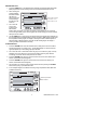
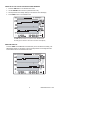
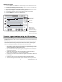
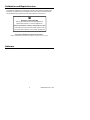
Alarm Conditions and the Alarm History
When in Standard View mode:
If the ALARM display icon is flashing – an Alarm condition currently exists.
If the ALARM display icon is ON steady – there are past Alarms to view in the Alarm
history. Use the ALARM button to view the Alarm history as described elsewhere in this
manual.
If an Alarm is tripped, press the ALARM button to silence it.
Press and hold the SET button for 2 seconds to clear an alarm through the external
relay module.
When in Alarm View or Time View mode:
If the ALARM display icon is flashing – the cursor is currently on an Alarm condition.
If the ALARM display icon is ON steady – there are past Alarms to view in the Alarm
history. Use the cursors or the ALARM button to view the Alarm history as described
elsewhere in this manual.
Note that the Alarm display icon and the external alarm relay module can be controlled
separately as indicated in the statements above.
Factory Default Settings
Default LCD mode: Standard View
o
Temperature Graph Vertical Resolution: 0 to 100 F
RH Graph Vertical Resolution: 0 to 100%
TEMP and RH Alarm Limits: 0 (low) and 100 (high)
Sample Rate: One (1) reading stored per minute
Battery Replacement
The 5-segment battery life indicator allows the user to track the status of the battery. When
all 5-segments are dark, the battery is fully charged. Segments switch off as the battery
ages. When the battery indicator has only one segment left the batteries must be replaced
immediately.
1. Open the battery compartment on the rear of the instrument
2. Remove the old batteries and replace with three (3) heavy duty alkaline ‘AA’
batteries observing polarity
3. Replace the battery compartment cover securely
4. The RH520 will require a “Programming Reset” to reset the display. Press the
RESET button located inside the battery compartment. “Reset” clears all settings.
Time, Date and the logging interval need to be entered. The measurement data and
alarm history, however, will still be retained in the non-volatile memory.
Optional Alarm Relay Module
The alarm output jack, located on the swivel push-button stand, drives the optional Remote
Alarm Relay Module (cable and relay). The relay module can be used to power external
warning or switching devices when programmed alarm limits are reached. Refer to the
manual supplied with the optional module for connection information.
14
Model RH520 Version 2.7 7/05