1
7 THE MODBUS PROTOCOL
The MODBUS protocol is a messaging structure developed by Modicon in 1979, used to establish masterslave / client-server communication between intelligent devices. It is a de-facto standard, truly open and the
most widely used network protocol in the industrial manufacturing environment. The Modbus protocol
provides an industry standard method that Modbus devices use for parsing messages. The Neoptix Modbus
option has been developed to support Modbus over a Serial Line protocol.
A master-slave type system has one node (the master node) that issues explicit commands to one of the
“slave” nodes and processes responses. Slave nodes (such as the T/Guard system) will not transmit data
without a request from the master node, and do not communicate with other slaves.
At the physical level, Modbus over Serial Line systems may use different physical interface (RS-485, RS232). RS-485 two-wire interface is the most common. As an add-on option (contact Neoptix), RS-485 fourwire interface may also be implemented. Furthermore, the Neoptix Modbus option has been successfully
tested over a TCP/IP network, using a Lantronix device server.
Neoptix has experienced some communication problems when configuring multiple Modbus-RS-485 systems
together. This is usually caused by unstable grounding problems, such as what can be encountered when
dealing with power transformers. To solve these problems, your RS-485 lines should be opto-isolated before
connecting them to the master Modbus bus. Refer to Section 7.6 for more information.
7.1 Configuring the Modbus option
Enabling and configuring the Modbus option must be done when the T/Guard system is not in Modbus
communication mode. When the Modbus option has been purchased, the help menu (see Section 5.2) is
slightly modified, as the following line is added:
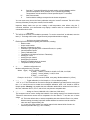
mb:
Modbus configuration tool, type: 'mb:?' for help;
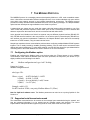
Typing “mb:?” gives:
Modbus configuration tool
mb:t,b,p,a<CR>
Where t (type)
b (baud)
p (parity)
a (addr)
: 0=RTU (default), 1=ASCII
: 0=9600, 1=19200
: 0=even (default), 1=odd, 2=none
: 1 to 247 (dec)
Example: mb:0,1,0,21
For RTU mode at 19200, even parity, Modbus address 21 (15hex)
Note for OptiLink-II software users: The Modbus parameters can also be set up using OptiLink-II. See
Section 6.4.
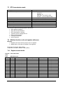
7.2 Supported serial transmission mode
The transmission mode defines the bit contents of the message bytes transmitted along the network, and
how the message information is to be packed into the message stream and decoded. The current
implementation of Neoptix-Modbus supports only the RTU mode; ASCII mode is a future option.
Document no. G1041r03
Copyright Neoptix Canada LP
29