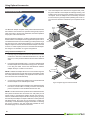
1
Routine QA Measurements Continued
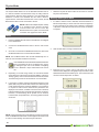
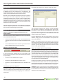
7. If connection is verified, select the appropriate treatment room
(RM1, RM2, etc) from the left side of the screen.
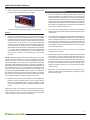
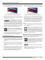
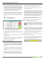
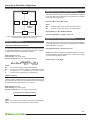
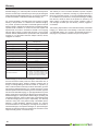
Real-Time Operation results from Static 5 Channel mode
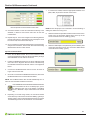
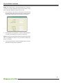
12. Click Save Results to save this measurement directly to the
database, or Reset to clear values and re-arm for the next
measurement.
13. Repeat steps 11-12 for other energies if not switching between
photons and electrons, otherwise enter the vault, flip the unit to
the correct side, and continue from step 10.
14. Once completed, the acquired measurements can be viewed for
analysis. For instructions, see the Data View and Downloading
Measurements section of this manual.
NOTE: Ensure the proper room is selected to avoid overwriting or
adding new data to the wrong room.
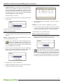
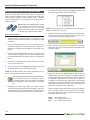
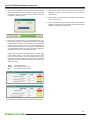
8. Select the Real-Time Operation tab at the bottom of the screen.
At this point, the Connection Status shown at the top of the
screen should be shown as “Waiting” (yellow).
9. Select the desired plan to test (D01-D25) from the Delivery area
on the upper right of the screen. The Connection Status should
now be shown as “Ready” (green).
Dynamic 5 Channel Room
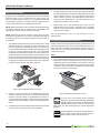
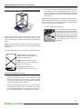
1. Place the QA Beamchecker Plus on the treatment couch
ensuring it is flipped to the Photon side as indicated by the large
white field labels on both sides of the device.
2. Position the QA BeamChecker Plus at 100 cm SSD with a field
size of 20 x 20 cm. Align the unit to the center of the field using
the QA BeamChecker Plus fiducials and the room alignment
lasers.
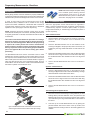
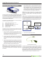
3. Connect the QA BeamChecker Plus to the PC as shown in
Figure 5 and exit the vault.
4. On the PC connected to the QA BeamChecker Plus, launch the
QA BeamChecker Plus Communication Software.
NOTE: The QA BeamChecker Plus should automatically turn on
when the communication software is launched.
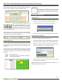
5.
If the database file associated with the QA BeamChecker
Plus connected to the PC is not already open, open it
by clicking the open icon on the toolbar or navigating
to File > Database > Open and browse for the correct
file.
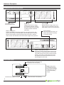
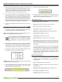
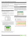
6. Depending on the tab being viewed, the Connection Status
shown at the top of the screen should read “Waiting” (yellow) or
“Ready” (green). If the Connection Status shows as red, see the
Troubleshooting section of this manual for more information.
21