1
USERS MANUAL
WaveSculptor PC Interface
TRI50.026 ver 1
28 February, 2007
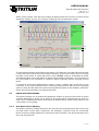
effect sensor output. Text box (d) of Figure 6 display either the success or failure of the
algorithm. Finally, list box (e) of Figure 6 displays the hall transition angles.
(a)
(b)
(c)
(d)
(e)
(f)
Figure 6 - An example PhasorSense acquisition.
To start a PhasorSense Acquisition press button (f) of Figure 6. You then have 10seconds
to spin the motor with an electrical motor frequency of more than 12Hz. Even on a fairly
low pole count motor of 4 pole pairs this is only 180RPM, which is achievable by hand.
The WaveSculptor uses hall edges to decide if the speed is sufficient, so if the halls are
not connected to the controller a "Failed to obtain sufficient speed" message will be
given.
It should be noted that PhasorSense needs to have a 1Mb/s CAN connection to the
controller. If any other CAN baud rate is selected, PhasorSense will not be a selectable
option. It may also be required to have only the WaveSculptor on the CAN bus, with other
items disconnected and/or not generating traffic.
5.1
PHASE VOLTAGE ERRORS
The phase voltage are all measured separately relative to ground, the phase to phase
voltages displayed in graph (a) of Figure 6 are produced by subtracting one from the
other. This is important to know when trying to identify which actual motor phase is not
connected or not working.
5.1.1
One Motor Phase Missing
The phase to phase voltage that does not rely upon the missing phase will be the only
one that looks correct (like a sinewave). For example, if phase A was not connected,
phase to phase voltage Vab and Vca would not work, however, Vbc would still work as it
does not rely phase A.
11 of 15