1
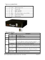
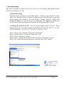
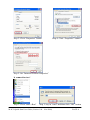
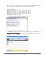
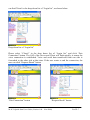
M-4132 Quick Start User Guide
1. Introduction
This manual introduces the M-4132’s basic setting and operation. The user can refer
to the user manual in the ICP DAS companion CD-ROM (Path: “CD:\napdos\
multimedia\m-4132\manual\m-4132 user manual.pdf”) for detail.
The manual is intended to help users quickly understanding and easily using of M4132. We use two M-4132s (one as Server, the other as Client), one Ethernet switch
and one PC to make a simple application here, as shown in figure 1. The PC is
prepared for setting and operating the M-4132.
Figure 1: Pair connection
2. Hardware configuration
Pin Assignment
M-4132 Quick Start User Guide (Version 1.00 Nov/2008)
PAGE: 1
7-pin screw terminal block
Pin
Name
Description
1
T.GND
2
Trig
Trigger input
3
D+
Data+ of RS-485
4
D-
Data- of RS-485
5
PWR
V+ of Power Supply (+10 to +30VDC)
6
GND
GND of Power Supply
7
F.G.
Frame Ground
GND of trigger input
LED Indicator
LED status indicator
Name
PWR
SA1
Status
Description
on
Power supply is ok.
off
Power supply has failed.
flash
It is receiving com port data via Ethernet.
Server: The Ethernet is initial ok and wait client to login.
SA2
flash slowly
flash fast
on
SA1
&
SA2
Client: The Ethernet is initial ok and login completely. It has
readied to enable voice and com port data connection.
It is sending or receiving voice data via Ethernet.
AP has some errors. (Client: Please check settings about IP &
DNS)
flash slowly (SA1 It is trying to establish the connection with server/client. If it
& SA2 flash at the can’t connect to server/client for a long time, please check it has
same time)
available network settings and is working well on Ethernet.
flash (SA1 & SA2 Server: Receive the request to connect from the client.
alternate flash)
Client: Request the server to connect.
M-4132 Quick Start User Guide (Version 1.00 Nov/2008)
PAGE: 2
3. System Setting
The M-4132 module is built-in web server, the user can configure and operate the M4132 by web browser (ex: IE).
Connection Setting
The user needs to prepare a system like figure 1. The user can connect PC and a
M-4132 by Ethernet switch. It can not connect with two M-4132 at the same time
before setting, else M-4132s’ IPs will conflict, because M-4132s’ default IPs
(Default IP address is “192.168.1.217”) are the same. The connection setting will
be described below and Microsoft Windows XP Professional SP2 is used.
a. Setting the Network of PC:Set the IP and Subnet mask of the PC. These
settings must have the same domain and different IP with the M-4132. (ex: M4132’s default IP = 192.168.1.217, PC’s IP = 192.168.1.210).
Step 1: Click “start->Settings->Network Connections”.
Step 2: Double click “Local Area Connection” icon.
Step 3: Click “Properties” button.
Step 4: Select “Internet Protocol(TCP/IP)” and click “Properties” button.
Step 5: Set “Internet Protocol Properties” and then click “OK” button.
Step 1: Click “Network Connections”
M-4132 Quick Start User Guide (Version 1.00 Nov/2008)
Step 2: Click icon
PAGE: 3
Step 3: Click “Properties” button
Step 4: Click “Properties” button
Step 5: Set “Internet Protocol Properties”
b. connection test:
Step 1: Click “start->Run”
Step 2: key in “cmd” and then click “OK” button
M-4132 Quick Start User Guide (Version 1.00 Nov/2008)
PAGE: 4
Step 3: Key in “ping 192.168.1.217” and click “Enter”. If the network settings
are all correct in PC and M-4132, these messages are shown below.
Response Message:
Reply from 192.168.1.217: bytes=32 time<1ms TTL=64
Reply from 192.168.1.217: bytes=32 time<1ms TTL=64
Reply from 192.168.1.217: bytes=32 time<1ms TTL=64
Reply from 192.168.1.217: bytes=32 time<1ms TTL=64
Ping statistics for 192.168.1.217:
Packets: Sent=4, Received=4, Lost=0 (0% loss)
c. Set Client:Open web browser (ex: IE, Mozilla, etc.) on PC and key in
http://192.168.1.217/main.htm in the Address line and then press “Enter” key
to link the M-4132’s web page.
M-4132 Quick Start User Guide (Version 1.00 Nov/2008)
PAGE: 5
z Key in user name and password and then click “Enter” button to login.
z Set Operation Mode = “VSoIP Client”, Host Name = Client1,
ServerIP(*) = ”192.168.1.217” and IP Address = “192.168.1.218” in
“Standard Config” web page. It is not need to change the other settings
and, then click “Save Setting” button to save the settings.
z Click “Reboot” button to reset M-4132 in the left page.
d. Setting Server
Now the user can connect the other M-4132 and Ethernet switch and don’t
need to remove the Client after the Client finished setting. If the Server has
default settings, it can work in the demo.
The Client will try to establish the connection with the Server after the Server
and Client power on. If PWR is on, SA1 is off and SA2 flash slowly one
minute later, it means the Server and Client work normally and ready to use.
e. Error check
If these leds statuses are not the same as the above, check the power supply,
network connection and system settings again.
Server: The user can open web browser and give the network address:
http://192.168.1.217/main.htm . After login, the user can click “Default
Setting” button and then click “Save Setting” button to recover the default
settings in the “Standard Config” page.
Client: The user can open web browser and give the www address:
http://192.168.1.218/main.htm . After login the user can click “Default Setting”
button in the “Standard Config” page and then set the client refer to the above.
Note: It must reset the M-4132 by power reset or click “Reboot” button after the
user changes the settings.
4. Communication test
If the above settings are all correct, the Server and Client should work normally. Open
web browser and give the network address: http://192.168.1.217/main.htm and then
login. The user can click “Operation Mode” hyperlink to operate the server. The user
M-4132 Quick Start User Guide (Version 1.00 Nov/2008)
PAGE: 6
can find Client1 in the drop down list of “Login list”, as shown below.
Drop down list of “Login list”
Please select “Client1” in the drop down list of “Login list” and click “Pair
Connection” button. The SA2 of the Server and Client will flash quickly; it means the
voice connection is established. Voice and serial data transferred from one side is
forwarded to the other side at that time. If the user wants to end the connection, the
user can click “Request Break” button.
“Pair Connection” button
“Request Break” button
M-4132 Quick Start User Guide (Version 1.00 Nov/2008)
PAGE: 7