1
R2 PLUS
Dear Customer:
Congratulations! We, STONEX are proud to present you with these series instrument.
Your total station is a rugged and reliable instrument whose performance and design are
not surpassed.
To fully appreciate and protect your investment, we suggest that you take the necessary
time to read and fully understand this manual. We have a dedicated service organization.
If the need arises, please don’t hesitate to contact us.
Thank you for your trust and confidence
1
R2 PLUS
Contents
1. Precautions for Safety .................................................................................1
1.1 Note ..............................................................................................................1
1.2 Definition of Indication ................................................................................2
1.3 Safety Standards for Laser ...........................................................................3
1.4 About User....................................................................................................4
1.5 Exceptions from Responsibility ...................................................................4
2. Preparation before Measurement ................................................................5
2.1 About Battery ...............................................................................................5
2.1.1 Battery Power Symbol ..............................................................................5
2.1.2 Replace the Battery ...................................................................................6
2.1.3 Recharge the Battery .................................................................................6
2.2 Setting Up the Instrument ............................................................................7
2.3 Centering and Levelling-Up .........................................................................7
2.4 Accurate Levelling-Up with Electronic Level on screen .............................8
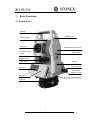
3. Basic Functions ...........................................................................................9
3.1 Nomenclature ...............................................................................................9
3.2 Basic Key Operation .................................................................................. 11
3.3 Display .......................................................................................................12
3.4 Mode Diagram............................................................................................13
3.5 Power On/Off .............................................................................................14
3.5 How to Input Number and Alphabet ..........................................................15
3.6 How to Configure .......................................................................................16
3.7 How to Set Parameters ...............................................................................17
3.7.1 Measure Condition Setting ......................................................................17
3.7.2 Instrument Basic Setting .........................................................................18
3.7.3 Communication Port Setting ...................................................................19
3.7.4 Unit Setting .............................................................................................20
3.7.5 Date & Time Setting ................................................................................21
3.7.6 Key Function Setting ...............................................................................21
3.7.7 EDM Setting ............................................................................................23
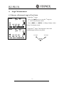
4. Angle Measurement ..................................................................................25
4.1 Measure a Horizontal Angle of Two Points ...............................................25
4.2 Set the Horizontal Angle to a Required Value ............................................26
5. Distance Measurement ..............................................................................27
6. Coordinate Measurement ..........................................................................29
1
R2 PLUS
6.1 Input the Occupied Point Data ...................................................................29
6.2 Azimuth Setting ..........................................................................................31
6.3 3D Coordinate Measurement .....................................................................32
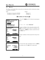
7. Stake out Measurement .............................................................................34
7. 1 Distance Stake out .....................................................................................34
7.2 Coordinates Stake out Measurement ..........................................................36
7.3 REM Stake out Measurement ....................................................................37
8. Area ...........................................................................................................39
8.1 Area Calculation by Measured Data...........................................................39
8.2 Area Calculation by Reading Existed Coordinates ....................................40
9. Offset Measurement ..................................................................................42
9.1 Single-distance Offset Measurement..........................................................42
9.2 Angle Offset Measurement .........................................................................44
9.3 Dual-Distance Offset Measurement ...........................................................45
10. MLM .......................................................................................................47
10.1 Measuring Distance between Two or More Points ..................................47
10.2 Change the Starting Point .........................................................................48
11. REM ........................................................................................................49
12. Resection .................................................................................................50
12.1 Coordinate Resection ...............................................................................51
12.2 Elevation Resection ..................................................................................52
12.3 Resection Calculation Process .................................................................54
12.4 Precautions When Performing Resection .................................................55
13. Point Projection .......................................................................................56
13.1 Define Baseline ........................................................................................56
13.2 Point Projection ........................................................................................58
14. Stake out Line ..........................................................................................59
14. 1 Define Baseline .......................................................................................59
14. 2 Stake Out Line-Point ...............................................................................59
14.3 Stake out Line/Line ..................................................................................61
15. Traverse Surveying..................................................................................63
15.1 Save Coordinate .......................................................................................63
15.2 Read Coordinate .......................................................................................64
16. Inverse .....................................................................................................65
17. Polar Coordinates Calculation ....................................................................66
18. Repetition Angle Measurement ..................................................................67
19. Arc Staking Out Measurement ...................................................................69
2
R2 PLUS
19.1 Two Point Arc Staking Out.......................................................................70
19.2 Three Point Arc Staking Out ....................................................................71
20. Road Staking Out Measurement.................................................................73
20.1 Input the Start Station ...............................................................................74
20.2 Input Road Horizontal Elements ..............................................................74
20.2.1 Input Line Element ................................................................................74
20.2.2 Input Circle Element .............................................................................75
20.2.3 Input Spiral Element..............................................................................76
20.2.4 Road Horizontal Element Editing .........................................................76
20.3 Input Road Vertical Elements ...................................................................78
20.3.1 Input Vertical Road Element. ................................................................78
20.3.2 Edit Vertical Road Element ...................................................................79
20.4 Road Calculation ......................................................................................81
20.4.2 Additional Station Setting .....................................................................82
20.4.3 Road Calculation ...................................................................................83
20.5 Road Staking Out Data View ...................................................................84
20.6 Road Stake Out .........................................................................................85
20.7 Road File Management ............................................................................86
20.7.1 Select a Road File ..................................................................................86
20.7.2 Rename a Road File ..............................................................................87
20.7.3 Delete a Road File .................................................................................88
20.7.4 Delete all Road Files .............................................................................89
21. Record .....................................................................................................90
21.1 Record Occupied Data .............................................................................90
21.2 Collect Angle Data ...................................................................................91
21.3 Distance&Coordinate Data ...................................................................92
21.4 Record Note..............................................................................................93
21.5 View Data .................................................................................................94
21.6 Select job ..................................................................................................95
22. JOB Management ....................................................................................96
22.1 Storage Media Select ................................................................................96
22.2 Select a JOB .............................................................................................97
22.3 Rename a JOB ..........................................................................................98
22.4 Delete a JOB.............................................................................................99
22.5 Output JOB Data ....................................................................................100
22.6 File Copy ................................................................................................101
22.7 Connect PC via USB port.......................................................................102
3
R2 PLUS
23. Known Data Management ........................................................................103
23.1 Input Known Point Coordinate by Keys ................................................103
23.2 Input Known Point Coordinate via RS-232C .........................................104
23.3 Delete known point coordinate ..............................................................105
23.4 View known points data .........................................................................106
23.5 Clear all known points’ data ...................................................................107
24. Code Management.................................................................................108
24.1 Edit Code list ..........................................................................................108
24.2 Clear all Codes .......................................................................................108
25. Warning and Error Messages ................................................................ 110
26. Check and Adjustment .......................................................................... 111
26.1 The Instrument Constant ........................................................................ 111
26.2 Tubular Level ......................................................................................... 112
26.3 Circular Level ......................................................................................... 112
26.4 The Optical Sight.................................................................................... 113
26.5 Optical Plummet (optional) ................................................................. 113
26.6 Laser Plummet........................................................................................ 114
26.7 Vertical Cross-hair on Telescope ............................................................ 114
26.8 Horizontal Collimation Error C.............................................................. 115
26.9 Tilt Sensor .............................................................................................. 116
26.10 Vertical Index Error .............................................................................. 117
26.11 EDM Optical Axis and the Telescope Sighting Axis Error .................. 119
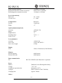
27. Technical Data .......................................................................................... 119
28. Accessories ...............................................................................................124
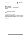
Appendix I: Atmospheric correction formula and chart (Just for reference) .103
Appendix Ⅱ:Correction for refraction and earth curvature .......................105
Appendix III:Connect the R2 PLUS series with PDA ................................106
Appendix IV Connect the R2 PLUS series and PDA with Bluetooth ............103
4
R2 PLUS
1. Precautions for Safety
1.1 Note
◆ Don’t collimate the sun directly
Avoid to insolate the instrument, and don’t collimate the sun directly for protecting eyes
and instrument.
◆ Avoiding the librations on the instrument
When transporting, keep the instrument in the case and try your best to lighten librations.
◆ Carry the instrument
When carrying,the instrument handle must be hold tight.
◆ Check the battery power
Before using it, you should check the power whether it is enough.
◆Battery Maintainence
If the instrument is not in using for a long time, the battery should be taken out from the
instrument and store in seperate place. Meantime, the battery should be charged every
month.
◆ Take out the battery
It is not suggested to take out the battery when the instrument is on, otherwise, the stored
data may be lost, so it is better to replace the battery after power off the instrument.
◆ Set up the instrument on the tripod
When using it please insure the connection between tripod and instrument is firm. It is
better to work with wooden tripod for the measurement accuracy.
◆ Assemble the tribrach on the instrument
The setting of tribrach would influence the accuracy. The tribrach should be check
frequently, the screw which connects the tribrach and alidade must be locked tightly. And
the central fixing screw should be tight.
◆ High temperature condition
Don’t put the instrument in high temperature condition for a long time, it is bad for the
instrument performance.
◆ Temperature changing sharply
The sharp temperature changing on the instrument or prism will shorten the distance
measurement range, for example, after taking the instrument out from a warm car to a
cold condition, wait for some time, it can be used when it adapts the surrounding
condition.
◆ The noise from the instrument
When the instrument working, it is normal if you hear the noise from instrument motor, it
1
R2 PLUS
will not affect the instrument work.
◆ Stored data responsibility
STONEX should not be held liable for the lost data because of wrong operation.
1.2 Definition of Indication
For the safe of your product and prevention of injury to operators and other persons as
well as prevention of property damage, items which should be observed are indicated by
an exclamation point within a triangle used with WARNING and CAUTION statements
in this manual.
The definitions of the indication are listed below. Be sure you understand them before
reading the manual’s main text.
!
!
WARNING:
CAUTION:
Ignoring this indication and making an
operation error could possibly result in death or
serious injury to the operator.
Ignoring this indication and making an
operation error could possibly result in personal
injury or property damage.
!
WARNING
● Do not perform disassembly or rebuilding. Fire, electric shock or burns could result.
Only STONEX authorized distributors can disassemble or rebuilt.
● Do not collimate the sun directly. The eye injury or blind could result.
● Do not cover the charger. Fire could be result.
● Do not use defection power cable, socket or plug. Fire, electronic shock could result.
● Do not use wet battery or charger. Fire, electronic shock could result.
● Do not close the instrument to burning gas or liquid, and do not use the instrument in
coal mine. Blast could be result.
● Do not put the battery in the fire or high temperature condition. Explosion, damage
could result.
● Do not use the battery which is not specified by STONEX. Fire, electric shock or burn
could result.
● Do not use the power cable which is not specified by STONEX. Fire could result.
● Do not short circuit of the battery. Fire could result.
● When this product encounters disturbance of severe Electrostatic Discharge, perhaps it
2
R2 PLUS
will have some degradation of performance like switching on/off automatically and so
on.
!
CAUTION
● Do not touch the instrument with wet hand. Electric shock could result.
● Do not stand or seat on the carrying case, and do not turn over the carrying case
arbitrarily, the instrument could be damaged.
● Be careful of the tripod tiptoe when setup or move it.
● Do not drop the instrument or the carrying case, and do not use defective belt, agraffe or
hinge. Instrument damage could result.
● Do not touch liquid leaking from the instrument or battery. Harmful chemicals could
cause burn or blisters.
● Please assemble the tribrach carefully, if the tribrach is not stable, series damage could
result.
● Do not drop the instrument or tripod, series damage could result. Before use it, check
the central screw is tight.
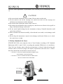
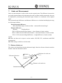
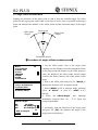
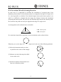
1.3 Safety Standards for Laser
STONEX R2 PLUS series adopt the class of Laser Product according to IEC Standard
Publication 60825-1 Amd. 2:2001. According this standard, EDM device is classified as
Class 3R Laser Product when reflectless measurement is selected, when the prism and
reflective sheet is selected as target, the output is equivalent to the safer class 1. Follow
the safety instructions on the labels to ensure safe use.
CAUTION: CLASS 3R LASER RADIATION WHEN OPEN
AVOID DIRECT EYE EXPOSURE.
CAUTION: CLASS 2 LASER RADIATION WHEN OPEN
DO NOT STARE INTO THE BEAM
Laser emit
3
R2 PLUS
!
WARNING
● Never point the laser beam at other’s eyes, it could cause serious injury.
● Never look directly into the laser beam source, it could cause permanent eye
damage.
● Never stare at the laser beam, it could cause permanent eye damage.
● Never look at the laser beam through a telescope or other optical devices, it
could cause permanent eye damage.
1.4 About User
1) This product is for professional use only!
The user is required to be a qualified surveyor or have a good knowledge of surveying, in
order to understand the user manual and safety instructions, before operating, inspecting
or adjusting.
2) Wear required protectors (safety shoes, helmet, etc.) when operating.
1.5 Exceptions from Responsibility
1) The user of this products is expected to follow all operating instructions and make
periodic checks of the product’s performance.
2) The manufacturer, assumes no responsibility for results of a faulty or intentional usage
or misuse including any direct, indirect, consequential damage, and loss of profits.
3) The manufacturer, assumes no responsibility for consequential damage, and loss of
profits by any disaster, (an earthquake, storms, floods etc.).
4) The manufacturer, assumes no responsibility for any damage, and loss of profits due to
a change of data, loss of data, an interruption of business etc., caused by using the
product or an unusable product.
5) The manufacturer, assumes no responsibility for any damage, and loss of profits
caused by usage except for explained in the user manual.
6) The manufacturer, assumes no responsibility for damage caused by wrong transport, or
action due to connecting with other products.
4
R2 PLUS
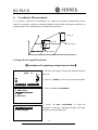
2. Preparation before Measurement
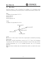
2.1 About Battery
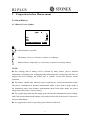
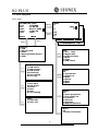
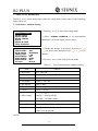
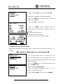
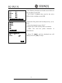
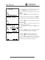
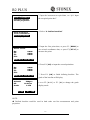
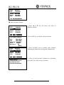
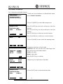
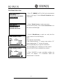
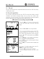
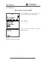
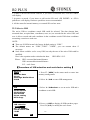
2.1.1 Battery Power Symbol
Meas
PC
0.0
ppm
0
SD
VA
II
HA
P1
DIST SHV1 SHV2 0 S E T
Measurement is possible
The battery is lower, it is better to replace or recharge it
Measurement is impossible, it is necessary to replace or recharge battery
NOTE:
◆ The working time of battery will be effected by many factors, such as ambient
temperature, recharging time, recharging and discharging times. On the data safe side, we
suggest the users recharge the battery full or prepare several full batteries before
operation.
◆ The battery symbol only indicates power capability for current measurement mode.
The power consumption in distance measurement mode is more than in angle mode, if
the instrument enters into distance measurement mode from angle mode, the power
maybe auto-off because of lower battery.
◆ The symbol only indicates the supply power but not the instantaneous power change.
And if the measurement mode changes, the symbol will not show the power’s decrease or
increase immediately.
◆ It is suggested to check every battery power before field work.
5
R2 PLUS
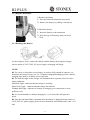
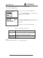
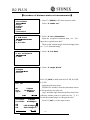
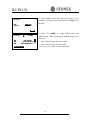
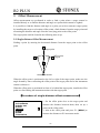
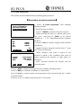
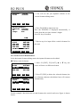
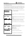
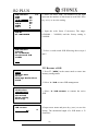
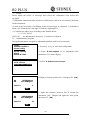
2.1.2 Replace the Battery
1) Remove the battery
① Press the button downward as shown left
② Remove the battery by pulling it toward you
2) Mount the battery
① Insert the battery to the instrument
② Press the top of the battery until you hear a
Click.
2.1.3 Recharge the Battery
As above figures show, connect the charger and the battery, then plug the charger
into the outlet of 110V-220V AC power supply, recharging will begin.
NOTE:
◆ For a new (or long time no use) battery, in order to fully extend its capacity, it is
absolutely necessary to carry out 3 to 5 complete charging/discharging cycles, and the
charging time must be 10 hours at least each time.
◆ The indicator light on the charger will illuminate three separate colors for varies
mode conditions:
Solid Red Light—indicates that the charger is working;
Solid Green Light— indicates that the charge has finished;
Flashing Red Light—indicates no battery on charging, poor connection or some
problems exist.
◆ It is recommended to continue charging for 1 or 2 hours after the light turn
green.
◆ Once the red light flashes constantly after the charger is plugged into the outlet of
110V-220V AC power supply, please remove the battery and reconnected it after 3 or 5
min.
6
R2 PLUS
2.2 Setting Up the Instrument
Mount the battery in the instrument before performing this operation because the
instrument will tilt slightly if the battery is mounted after leveling.
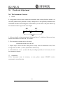
I. Set up the tripod first: extend the extension legs to suitable lengths and tighten the
screws on the midsections. Make sure the legs are spaced at equal intervals and the head
is approximately level. Set the tripod so that the head is positioned over the surveying
point. Make sure the tripod shoes are firmly fixed in the ground.
II. Mount the instrument on the tripod head. Supporting it with one hand, tighten the
centering screw on the bottom of the unit to make sure it is secured to the tripod.
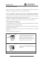
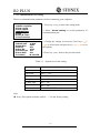
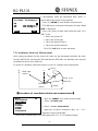
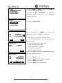
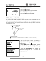
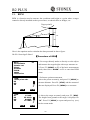
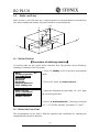
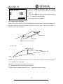
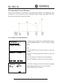
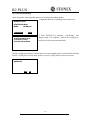
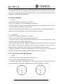
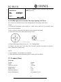
2.3 Centering and Levelling-Up
1. Position tripod legs so that the plummet is aimed to the ground mark point. Turn the
focusing ring of the optical plummet to focus.
2. Turn three footscrews of the tribrach till the center of reticle exactly coincides with the
surveying point in any position.
3. Move the tripod legs to centre the circular level. The instrument is now roughly
leveled-up.
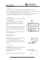
4. Center the bubble in the circular level
Screw B
Screw A
Loosen the horizontal motion clamp, and
turn the instrument till the plate level is
parallel to a line shaped with screws A
and B. Adjust the screws A and B to make
the bubble in the center of the level.
Plate level
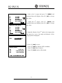
Screw C
Screw B
Screw A
Turn the instrument approximately 90°.
Adjust screw C, till the bubble in the center
of the level.
Screw C
Repeat above steps until the bubble remains in the center of the plate level while
7
R2 PLUS
the instrument is rotated to any position.
5. Center the surveying point again
Loosen the centering screw slightly. Looking through the optical plummet eyepiece, slide
the instrument over the tripod head until the surveying point is exactly centered in the
reticle. Re-tighten the centering screw securely.
6. Check again to make sure the bubble in the plate level is centered.
If not, repeat procedure 4.
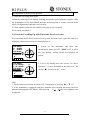
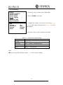
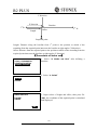
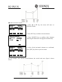
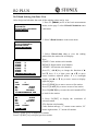
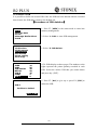
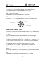
2.4 Accurate Levelling-Up with Electronic Level on screen
It is convenient for R2 PLUS series to level-up with electronic level, especially when it is
difficult to observe the circular level and plate level.
Tilt Value
X
OVER
Y
OVER
Tilt Mode
XONYON
Lightness
1. Power on the instrument and enter into
X
measurement mode, press F1: [TILT] at P3 or press
Y
key {BS} directly, and the electric level displays on
screen.
0
Tilt Value
X -0°
°00’02’’
Y -0°
°00’03’’
Tilt Mode
XONYON
Lightness
0
2. Level it by turning three foot screws, see above
X
operation “3. Center the bubble in the plate level”. Be
Y
sure the ● is always in the
center.
Note:
1. On this menu you can turn on/off the X/Y compensator by pressing ▲or ▼ key.
2. If the instrument is equipped with laser plummet, after opening this menu, the laser
plummet adjusting bar will display. With pressing
or
key the laser lightness can
be adjusted.
8
R2 PLUS
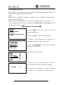
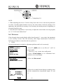
3. Basic Functions
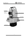
3.1 Nomenclature
Handle
Handle screw
Optical sight
Objective
Instrument height mark
Vertical motion
clamp
Vertical
tangent screw
Model label
Plate level
Battery
Horizontal
motion clamp
Screen
Horizontal
tangent screw
Keypad
SD card slot&USB port
Tribrach
9
R2 PLUS
Focusing knob
Eyepiece
Instrument height mark
Serial number
RS-232C port
Leveling screw
10
R2 PLUS
3.2 Basic Key Operation
Keys
F1~F4
0~9
Description
Select the functions matching the softkeys
1.Input number when numeric input
2.Input characters when alphabetic input
●
Input a decimal point
±
Input plus/minus sign
Power
Power on/off
★
Enter into setting mode directly
Cnfg
Enter into config mode directly
ESC
Escape to the previous menu or mode
Shift
1. Shift between number and alphabetic when inputting
2.Shift targets model when measuring
BS
1. Delete the character at the left of the cursor when inputting
2. Open electronic level menu
Space
1. Input a black space when inputting
2. Input the target or instrument height
Func
Turn page
ENT
1. Select/Accept input data
2. Accept the option when selecting
11
R2 PLUS
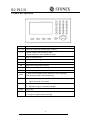
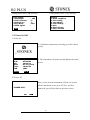
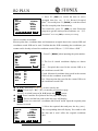
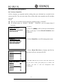
3.3 Display
The LCD could display 8 lines with 24 characters per line. In measurement mode, it
displays some common information in above 7 lines and displays soft functions in the last
line.
Status screen
Instrument model
STONEX R2 PLUS
S/N
STN3050
Ver
12-04-26
Date
08/15/2006
Time
10:01:59
JOB
JOB1
MEAS
Application software version
Current power
The active JOB
MEM
Basic measure mode
Target type
Meas
PC
0.0
ppm
0
SD
VA
II
HA
P1
DIST SHV1 SHV2 0 S E T
Measuring
Dist
Fine
-----※
※
ppm 0
STOP
Measuring now
12
Current memory
Face II
Page
R2 PLUS
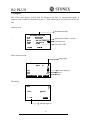
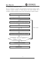
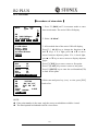
3.4 Mode Diagram
Meas mode
STONEX R2 PLUS
S/N
STN3050
12-04-26
Ver
Date
08/15/2006
Time
10:01:59
JOB
JOB1
[MEAS]
[MEM]
ppm
MEM
{ESC}
{2}
{3}
CORD MENU HOLD H S E T
[REC]
JOB
1.JOB select
2.JOB rename
3.JOB delete
4.Download
5.Com setting
6.File copy
Known data
1.Key input
2.Com input
3.Delete
4.View
5.Clear
6.Com setting
SD
VA
II
HA
EDM O C C OFST R E C
Memory
1.JOB
2.Known data
3.Code
4.Storage Media Select
5.USB
{1}
PC
0
{ESC}
MEAS
Meas
0
[MENU]
JOB 1
REC
1.Occ. data
2.Angle data
3.Collect Points
4.Note
5.View
6.JOB select
Menu
P1
1.Coordinate
2.Stake out
3.Area
4.Offset
5.MLM
6.REM
7.Resection
Menu
P2
1.Point projection
2.Line stake out
3.Traverse
4.Inverse
5.Polarize
6.Repeat Measure
7.Arc staking out
Code
1.Code Edit
2.Clear List
Menu
P3
1.Road Calculation
13
R2 PLUS
Setting mode (Press {★} directly)
Inst Config
1.Backlight
2.LCD contrast
3.Reticle lev
4.Key Beep
5.EDM signal
Config mode (Press {Cnfg} directly)
Config
1.Meas condition
2.Inst config
3.Inst adjust
4.Com setting
5.Unit
6.Date & Time
7.Key Function
: YES
:5
:7
:YES
:
EDM
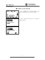
3.5 Power On/Off
I. Power on
1. Confirm the instrument is leveling, press the red key
{POWER}.
Initing……
STONEX R2 PLUS
S/N
STN3050
Ver
10-06-21
Date
07/12/2010
Time
10:01:59
JOB
JOB1
MEAS
2. The instrument will power on and display the status
screen.
MEM
II. Power off
Press {POWER} key, the instrument will ask you to turn
off the instrument or not, press F3(Yes), it will be
turned off, press F4(No) back to previous screen.
POWER OFF?
YES
NO 1
14
R2 PLUS
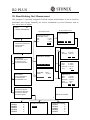
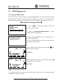
3.5 How to Input Number and Alphabet
001:CODEAB
002:
003:
004:
005:
006:
007:
↑↓.P
↑↓ T O P LAST DEL
1. Enter into input code status (See§21.1 Input a
code), the cursor is blinking and ready to input. The
note “A” at the top right corner shows the active input
mode, you can press the key {shift} to switch between
alphabet and number.
001:CODEAB
002:MY01
003:
004:
005:
006:
007:
↑↓.P
↑↓ T O P LAST DEL
2. Input the code in turn and press the blue key {ENT}
to save it. You can press key {BS} to delete your
wrong input before the cursor. The max length of a
code is 16 characters.
15
R2 PLUS
Inst Config
1.Backlight
2.Laser
3.LCD contrast
4.Reticle lev
5.Key Beep
6.EDM signal
EDM
: YES
:NO
:5
:7
:YES
:
Inst Config
1.Backlight
2.Laser
3.LCD contrast
4.Reticle lev
5.Key Beep
6.EDM signal
EDM
: YES
:NO
:5
:7
:YES
:
Inst Config
1.Backlight
2.Laser
3.LCD contrast
4.Reticle lev
5.Key Beep
6.EDM signal
EDM
Inst Config
1.Backlight
2.Laser
3.LCD contrast
4.Reticle lev
5.Key Beep
6.EDM signal
: YES
:NO
:5
:7
:YES
:
: YES
:NO
:5
:7
:YES
:
EDM
Inst Config
1.Backlight
2.Laser
3.LCD contrast
4.Reticle lev
5.Key Beep
6.EDM signal
EDM
: YES
:NO
:5
:7
:YES
:
Inst Config
1.Backlight
2.Laser
3.LCD contrast
4.Reticle lev
5.Key Beep
6.EDM signal
EDM
: YES
:NO
:5
:7
:YES
:26
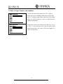
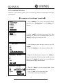
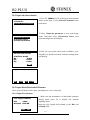
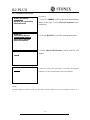
3.6 How to Configure
Press key {★} on panel directly to enter into in any
status, and do some basic settings.
1. Backlight
Press numeric key {1}, then press left key { } or
right key { } to turn on or not.
2.Laser pointer on/off
Press numeric key {2}, then press left key { } or
right key { } to turn on/off telescope laser pointer.
3. LCD contrast
Press numeric key {3}, then press left key { } or
right key { } to adjust it.
4. Reticle level
Press numeric key {4}, then press left key { } or
right key { } to adjust it. If the value is zero, the
illumination is turned off.
5. Key beep
Press numeric key {5}, then press left key { } or
right key { } to turn on key beep or not, if you select
NO, you will not hear the beep voice when press the
key.
6. EDM returned Signal
Aim at a target, then press numeric key {6} and the
instrument will beep, the EDM returned signal value
will display simultaneously.
7. EDM setting menu
Press function key {F1} to open the EDM setting
menu.
16
R2 PLUS
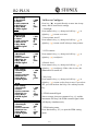
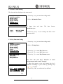
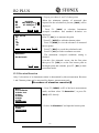
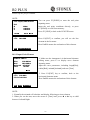
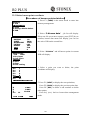
3.7 How to Set Parameters
Press key {Cnfg} on the keyboard to enter into config mode in any status, all the following
items can be set.
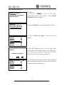
3.7.1 Measure Condition Setting
1. Press key {Cnfg} to enter into config mode.
Config
1.Meas condition
2.Inst config
3.Inst adjust
4.Com setting
5.Unit
6.Date & Time
7.Key Function
2. Select “1.Meas condition” to set measurement
parameters. All items display on two pages.
Meas condition
P1
1.Dist mode :HD
2.Tilt adjust :XONYON
3.Refr.coeff
:.20
4.VA display :VA
5.HA display :HAR
6.HA buzzer :No
7.Coord
:N-E-Z
3. Change the settings if necessary. Press keys { }/
{ } to select items and press keys { }/ { } to set
options.
4. Press key {ESC} back to the previous mode.
Table 3-1
List of measurement condition setting
Options
Item
1.Dist mode
SD﹡/HD/VD
2.Tilt adjust
XonYon﹡/XonYoff/XoffYoff
3.Refr.coeff
.14﹡/.20/No
4.VA display
Zenith﹡/VA/V90
5.HA display
HAR﹡/HAL
6.HA buzzer
No﹡/Yes
7.Coord
N-E-Z﹡/E-N-Z
1.Min reading
1〞﹡/5〞/10〞;
0.0002g﹡/0.001g/0.002g;
0.005mil﹡/0.02mil/0.05mil
2.ppm correct
No﹡/Yes (auto correct ppm by sensors or not
Code effect
The manual input code is available once or always
Vdist mode
Display mode of vertical distance: to instrument
center or to the ground
NOTE:
17
R2 PLUS
◆ Every first options with the symbol “﹡” are the factory setting.
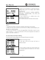
3.7.2 Instrument Basic Setting
1. Press key {Cnfg} to enter into config mode.
Config
1.Meas condition
2.Inst config
3.Inst adjust
4.Com setting
5.Unit
6.Date & Time
7.Key Function
Inst config
1.Auto off
2.LCD contrast
3.Reticle adjust
2. Select “2.Inst config” to set instrument basic
parameters. Three items display.
:15min
:9
:7
3. Change the settings if necessary. Press keys { }/
{ } to select items and press keys { }/ { } to set
the options.
4. Press key {ESC} back to the previous mode.
Table 3-2 Option list of basic setting
Options
Item
1.Auto off
30min﹡/No/5min/10min/15min
(The instrument would power off automatically to
save battery if no operation in setting time)
2.LCD contrast
0~13 (9﹡)
3.Reticle adjust
0~9 (7﹡)
NOTE:
◆ The options with the symbol “﹡” are the factory setting.
18
R2 PLUS
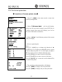
3.7.3 Communication Port Setting
Please set communication parameters before connecting your computer.
Config
1.Meas condition
2.Inst config
3.Inst adjust
4.Com setting
5.Unit
6.Date & Time
7.Key Function
1. Press key {Cnfg} to enter into config mode.
Com setting
:1200
1.Baud rate
:8bit
2.Data bits
:No
3.Parity
:1bit
4.Stop bit
5.Check sum :No
:No
6.Xon/Xoff
7.Comode
:B-TOOTH
3. Change the settings if necessary. Press keys { }/
{ } to select items and press keys { } / { } to set
the options.
2. Select “4.Com setting” to set the parameters of
communication port.
4. Press key {ESC} back to the previous mode.
Table 3-3 Option list of com setting
Options
Item
1.Baud rate
1200﹡/2400/4800/9600/19200/38400
2.Data bits
8bit﹡/ 7 bit
3.Parity
No﹡/ Even/ Odd
4.Stop bit
1bit﹡/ 2bit
5.Check sum
No﹡/ Yes
6.Xon/Xoff
No﹡/ Yes
7.Com mode
RS-232/B-TOOTH
Note:
◆ Every first options with the symbol “﹡” are the factory setting.
19
R2 PLUS
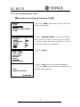
3.7.4 Unit Setting
1. Press key {Cnfg} to enter into config mode.
Config
1.Meas condition
2.Inst config
3.Inst adjust
4.Com setting
5.Unit
6.Date & Time
7.Key Function
Unit
1.Temp.
2.Pressure
3.Angle
4.Dist
2. Select “5.Unit” to set unit.
:℃
℃
:hPa
:degree
:meter
3. Change the settings if necessary. Press keys { }/
{ } to select items and press keys { } / { } to set
the options.
4. Press key {ESC} back to the previous mode.
Table 3-4 Option list of unit setting
Options
Item
1.Temp.
℃﹡/ ℉
2.Pressure
hPa﹡/ mmHg / inchHg/mbar/psi
3.Angle
degree﹡/ gon / mil
4.Dist
meter﹡/ Us-feet/Int-ft
Note:
◆ Every first options with the symbol “﹡” are the factory setting.
20
R2 PLUS
3.7.5 Date & Time Setting
The date and time displays at the status mode.
1. Press key {Cnfg} to enter into config mode.
Config
1.Meas condition
2.Inst config
3.Inst adjust
4.Com setting
5.Unit
6.Date & Time
7.Key Function
2. Select “6.Date & Time”.
3. Input date
month/date/year.
Date and Time
Date
Time
:08/08/2006
:10:00:00
and
time.
The
date
format:
4. Press key {ENT} to save settings and back to the
previous mode.
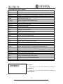
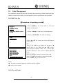
3.7.6 Key Function Setting
1. Press key {Cnfg} to enter into config mode.
Config
1.Meas condition
2.Inst config
3.Inst adjust
4.Com setting
5.Unit
6.Date & Time
7.Key Function
2. Select “7.Key Func”.
3. Press key {1} to enter Key Set menu
4. Press key {2} to enter Key Save menu
5. Press key {3} to enter Key Resume menu
KEY FUNCTION
1.Key Set
2.Key Save
3.Key Resume
KEY SET
DIST SHV1 SHV2 0SET
CORD MENU HOLD HSET
EDM OCC OFST REC
Key Set: the soft key’s function at basic
measurement mode can be changed
1. Move the cursor to the key, change the key’s
function according to your need by pressing keys
{ }/ { } to select.
2. Press Key {OK} to confirm the key defined
OK
21
R2 PLUS
Following items can be defined:
Items
Descriptions
DIST
Start distance measure
SHV1
Display switching between SD/HAVA, HD/HA/VA and VD/HA/VA
SHV2
Display switching between SD/HD/VD and SD/HA/VA
0SET
Set horizontal angle to 0
CORD
Enter coordinate measurement menu
MENU
Enter program menu
HOLD
Hold the horizontal angle
HSET
Set horizontal angle
EDM
Enter distance setting menu
OCC
Setting the station point
OFST
Enter offset measurement menu
REC
Enter points collection menu
RES
Enter resection program menu
REMS
Enter angle repeat measurement menu
MLM
Enter missing line measurement menu
S.O.
Enter stake out measurement menu
TILT
Display electronic level
REM
Enter remote elevation measurement menu
HARL
Horizontal angle display switching between HR and HL
ZA/%
Vertical angle display switching grade and zenith
OUT
Output the current measurement data via RS-232C port
AREA
Enter area measurement menu
ROAD
Enter road measurement menu
IHT
Enter instrument height setting menu
LSO.
Enter line stake out measurement menu
PROJ
Enter point projection measurement menu
KEY FUNCTION SAVE
1.User Define 1
2.User Define 2
Key Save
1. Press key {1} to save the current key setting in
User Define 1
2. Press key {2} to save the current key setting in
User Define 2
22
R2 PLUS
KEY FUNCTION RESUME
1.User Define 1
2.User Define 2
3.Default Define
Key Resume
1. Press key {1} to resume the User Define 1 as the
current Key setting
2. Press key {2} to resume the User Define 2 as the
current Key setting
3. Press key {3} to resume the Default Define as the
current Key setting
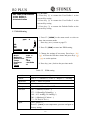
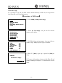
3.7.7 EDM Setting
Meas
1. Press F1: [MEAS] in the status mode or select to
enter into measure mode.
Press key {Func} to turn to page P3.
PC
0.0
ppm
0
SD
VA
HA
EDM OCC
II
P1
OFST R E C
EDM
Mode
Reflector
Prism const
Temp.
Pressure
ppm
0PPM
:Fine “r”
:Prism
:0
:20℃
℃
:1013hPa
:0
2. Press F1: [EDM] to enter into EDM setting.
3. Change the settings if necessary. Press keys { }/
{ } to select the first three items and press keys { }
/ { } to set the options.
4. Press key {ESC} back to the previous mode.
Table 3-5
EDM setting
Options
Item
1.Mode
Fine “r”﹡/ FineAVG 3 / Fine “s” / Rapid “s” / Tracking
2.Reflector
Prism﹡/ Sheet/ No prism
3.Prism const
-99~99
4.Temp.
-30~60℃(20℃﹡)/-22~140℉
5.Pressure
500~1400hPa(1013hPa﹡);
375~1050mmHg(760mmHg﹡);
14.8~41.3 inchHg (29.9inchHg﹡)
500~1400mbar(1013mbar﹡);
7.2~20.3Psi(14.7Psi﹡)
6.ppm
-499~499(0﹡),
Press F1: [0PPM] to set temperature, pressure and ppm as
factory setting.
23
R2 PLUS
Note:
◆ Options with the symbol “﹡” are the factory setting.
◆ ppm value could be calculated by inputted temperature and pressure, or input directly.
If the option of “ppm correct” is set as “Yes”, the temperature, pressure and ppm can not
be inputted by hand.
◆ This operation is also available in stake out mode.
◆ You can press star{★}/F1[EDM] key to enter EDM setting menu directly.
24
R2 PLUS
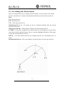
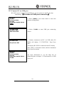
4. Angle Measurement
4.1 Measure a Horizontal Angle of Two Points
Meas
PC
0.0
ppm
0
SD
VA
85°
°55′
′50″
″
II
HA
0°
°00′
′00″
″
P1
DIST SHV1 SHV2 0 S E T
Meas
PC
0.0
ppm
0
1. Sight the 1st target.
Press F4: [0SET] twice to set the 1st target as
0°at P1 in the measure mode.
Press [SHV1] or [SHV2] to change display status
firstly if in distance mode.
2. Sight the 2nd target. The displayed value is the
included angle between two points.
SD
VA
85°
°55′
′50″
″
II
HA 156°
°13′
′14″
″ P1
DIST SHV1 SHV2 0 S E T
1st target
25
2nd target
R2 PLUS
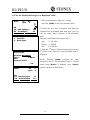
4.2 Set the Horizontal Angle to a Required Value
Meas
1. Take your instrument sight the 1st target.
Press F4: [HSET] at P2 in the measure mode.
PC
0.0
ppm
0
SD
VA 302.5432gon
II
HA 0.0000gon
P2
CORD MENU HOLD H S E T
Set H Angle
1. Azimuth
2. Back sight
Set H Angle
Azimuth -399.9998
Tgt.H
0.000m
PT#
Observe point!
OK
Meas
PC
ppm
0
0
2. Select the first item 1.Azimuth, and input the
required value in Azimuth filed, then press {ENT} to
save the value. And it displays as the horizontal
angle.
The range and format of the input value:
gon:
0~399.9999
degree: 0 ~359.5959
mil:
0~6399.990
3. Sight the 2nd target. The horizontal angle from the
2nd target to the value set as the horizontal angle is
displayed.
NOTE: Pressing [HOLD] performs the same
function as above. The horizontal angle is in hold
status when [HOLD] is flashing, press [HOLD]
again to releasse the hold status.
SD
VA 302.5432gon
II
HA 399.9998gon
P1
CORD MENU HOLD H S E T
26
R2 PLUS
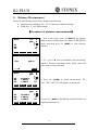
5. Distance Measurement
Please set the following items before distance measurement:
●
Measurement condition ( See §3.8.1 Measure Condition Setting)
●
EDM (See §3.8.6 EDM setting )
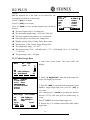
【Procedure of distance measurement】
】
Meas
PC
ppm
0
0
SD
HD
VD
II
P1
1. Aim at the target, press F3:[SHV2], the display
mode of basic measurement will change to SD/HD/VD
mode, and then press F1: [DIST] to start measure
distance.
DIST S H V 1 SHV2 0SET
Dist
Fine
-----※
※
STOP
Meas
SD
HD
VD
2. The symbol “*
*” moves continually when measuring
distance. Distance measuring mode, prism const and
ppm value are also presented.
ppm 0
PC
ppm
10.329m
7.009m
7.586m
0
0
II
P1
3. Press F4: [STOP] to finish measurement. The
“SD”,”HD”, and”VD” will display as shown left.
DIST S H V 1 SHV2 0SET
Meas
SD
HD
VD
PC
ppm
10.329m
7.009m
7.586m
0
0
II
P1
DIST S H V 1 SHV2 0SET
4. Press F3: [SHV2], SD/HD/VD and SD/VA/HA are
displayed alternatively.
27
R2 PLUS
NOTE:
◆ Make sure that the target setting in the instrument matches the type of target used.
◆ If the objective lens is dirty, it will affect the accurate of measured results. Dust it off
with your special brush and wipe it with your special cloth (in your carrying case)
before putting away.
◆ If an object with a high reflective factor (metal, white surface) exists between the
instrument and the target when measuring, the accuracy of the measured results will
be affected.
◆ An angle is also able to be measured when distance measurement.
◆ Measurement will automatically stop after a single measurement if the EDM mode is
single (Fine “S” / Rapid “S”).
◆ If the distance measurement mode is average “Fine AVG”, the measured distances are
displayed as “-1”,”-2”,”-3”…”-9” in turn, and the average value will display behind
“-A” once the selected time’s measurement has been finished.
28
R2 PLUS
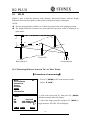
6. Coordinate Measurement
It is possible to find the 3D coordinates of a target by coordinate measurement. Please
input the occupied coordinate, instrument height, target height, backsight coordinate (or
azimuth angle) and azimuth before coordinate measurement.
○
N
Target Ht
Z
Inst. Ht
Target point
Occiped point
E
6.1 Input the Occupied Point Data
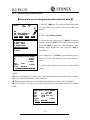
【Procedure of inputting occupied point data】
】
Meas
PC
0.0
ppm
0
SD
VA
II
HA
P1
CORD MENU HOLD H S E T
Coordinate
1. JOB select
2. Occ. orientation
3. EDM
4. Measure
Coord
1. Occ. coordinate
2. Set H angle
1. Measure the height of target and instrument with a
tape, etc.
2. Press F1: [CORD] at P2 in the measurement mode.
3. Select “2. Occ. orientation”.
4. Select “1. Occ. coordinate” to input the
occupied coordinates, instrument height and target
height in corresponding field.
29
R2 PLUS
PT#
Inst.H:
1.500m
Code:
sdds
N0:
0.000
E0:
0.000
Z0:
0.000
User
READ R E S R E C 0O K0
5. Press F3: [REC] to record the data in active
occupied data list, see “ § 21.1 Record Occupied
Data”. You could press F1: [READ] to read the existed
data for occupied point from memory.
You could also press F2: [RES] to enter Resection
program to get the station point coordinate, see Ҥ12.
Resection”. Press F4: [OK] to confirm your setting.
How to read the existed data:
Known point data, coordinate data and instrument occupied data in the current JOB and
coordinate search JOB can be read. Confirm that the JOB containing the coordinates you
wanna read is already selected in coordinate search JOB, see “§22.2 Select a JOB ”.
PT#
56
Inst.H:
1.500m
Code:
sdds
N0:
0.000
E0:
0.000
Z0:
0.000
User
READ R E S R E C 0O K0
Occ.
Coord
Coord
PT#
Coord
Occ.
15
56
20
50
45
2
3
↑↓.P T O P LAST SRCH
↑↓
1. Press F1: [READ] when inputting the point number.
2. The list of existed coordinate displays as shown
left:
Occ. : Occupied data saved in the current JOB or in
the coordinate search JOB.
Coord: Measured coordiante data saved in the current
JOB or in the coordinate search JOB
Pt# : Known point data saved in the current JOB or in
the coordinate search JOB.
◆ [↑↓.P] : Press keys { }/ { } to move one by one.
◆ [↑↓.P
↑↓ ]: Press keys { ▲ }/ {▼ } to turn the previous/next page.
Press F1 to switch between [↑↓.P
↑↓ ] status and [↑↓.P
↑↓ ] status.
◆ [TOP]: Press it and the first point on the first page will display.
◆ [LAST]: Press it and the last point on the last page will display.
◆ [SRCH]: Press it to enter into “coordinate data search” mode. Input the required point
number to search.
3. Select the required data and press the key {ENT}.
PT#
5
Inst.H:
1.500m
The corresponding data will display. You could re-edit
Code:
sdds
the data and it won’t affect the original coordinate
N0:
100.000
E0:
100.000
data.
Z0:
010.000
User
READ R E S R E C
0O K0
30
R2 PLUS
4. Press F4: [OK] to save the setting.
NOTE:
◆ The point number that was read is displayed until the current JOB is changed or a new
point number is selected.
◆ If more than two points with the same point name exist in the current JOB, the
instrument finds the first recorded data only.
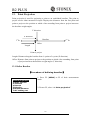
6.2 Azimuth Setting
The azimuth of backsight could be inverse calculated by the coordinates of occupied and
backsight.
N
0
Azimuth
Instrument Station
Angle
Set H angle
1.Azimuth
2.Backsight
1. Select “2. Set H angle”, see “§6.1 Input the
occupied point data”. Then select “2. Backsight”.
Set H angle/BS
NBS:
EBS:
ZBS:
Pt#
20.000
20.000
20.000
P20
READ
0O K0
Set H angle/BS
Azimuth
450000
Tgt.H
0.000m
Pt#
MEAS
E
REC
OK
2. Input the coordinate of backsight. You could also
press F1: [READ] to select existed point data. If you
input the same coordinates with the occupied point, a
message “Same coordinates” will appear and disappear
in 5sec,please re-input the data.
3. Press F4: [OK] to accept the inputted occupied and
backsight coordinates, the calculated azimuth angle will
display.
4. Aim at the backsight point, and then press F1:[MEAS]
to check the backsight, or press F3: [REC] to record and
set the station, then back to the previous mode. You
could also press F4: [OK] to set the station, but the data
will not be recorded.
31
R2 PLUS
Note:
◆ You can select “1. Azimuth” to input the azimuth angle directly.
◆ After input the coordinate of backsight, you can press F1:[MEAS] to check for
backsight checking, HD between station and backsight, dHD and dVD between calculated
backsight and measured backsight will be display.
Set H angle/BS
Azimuth
45°
°00′
′00″
″
Tgt.H
1.000m
Pt#
HD
0.163m
dHD
-0.163m
dVD
11.655
REC
OK
press F3: [REC] to record and set the station, then
back to the previous mode. You could also press F4:
[OK] to set the station, but the data will not be
recorded.
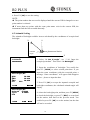
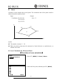
6.3 3D Coordinate Measurement
The target coordinate could be measured after the setting of occupied point and backsight
azimuth.
The formular used to calculate:
N1=N0+S×sinZ×cosAz
E1=E0+S×sinZ×sinAz
Z1=Z0+S×cosZ+IH-TH
Where:
N0-E0-Z0: occupied point coordinates
S:SD
Z:Zenith angle
Az:Azimuth angle
IH:Instrument height
TH:Target height
Z
Zenith angle
SD
Target height
Target (N-E-Z)
IH
HD
N0-E0-Z0
N
E
Azimuth angle
32
R2 PLUS
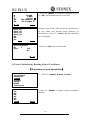
【Procedure of 3D coordinates measurement】
】
Coordinate
1. JOB select
2. Occ. Orientation
3. EDM
4. Measure
Coord Measure
N
E
Z
VA
HA
MEAS
1000.000
1000.000
10.466
132.3648gon
II
150.3536gon
TAGT
REC
1. Aim at the target point.
2. Select “4. Measure” to start. The coordinate value
of the target is displayed.
3. Press F2: [TAGT] to re-input the occupied data if
necessary, see “§6.1 Input the occupied point data”.
You can press F4: [REC] to record the data.
4. Aim at the next target, press F2: [TAGT] to re-input
the target height if necessary, and press F1: [MEAS] to
continue. Follow this operation till all targets have
been measured.
5. Press key {ESC} back to the coordinate mode.
33
R2 PLUS
7. Stake out Measurement
Stake out measurement is used to stake out the required point. The difference between the
previously inputted data to the instrument (the stake out data) and the measured value can
be displayed by measuring the horizontal angle, distance or coordinates of the sighted
point.
The horizontal angle difference and distance difference are calculated and displayed using
the following formulas:
Horizontal angle difference
dHA=Horizontal angle of stake out data – measured horizontal angle
Distance difference
Distance
Displayed item
SD: S-O SD=measured slope distance – slope distance of stake out data
HD: S-O HD=measured horizontal distance – horizontal distance of stake out data
VD: S-O VD=measured height difference – height difference of stake out data
NOTE:
◆ Stake out data can be input in various modes: SD, HD, VD, coordinates and REM
measurement.
◆ EDM settings could be set in this mode.
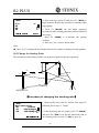
7. 1 Distance Stake out
The point to be found based on the horizontal angle from the reference direction and the
distance from the instrument station.
Position to be stake out
distance
Reference direction
Present target
position
Distance to be stake out
Instrument station
34
R2 PLUS
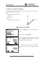
【Procedure of distance stake out measurement】
】
Menu
1.Coordinate
2.Stake out
3.Area
4.Offset
5.MLM
6.REM
7.Resection
P1
1. Press F2: [MENU] at P2 in the measure mode.
Select “2. Stake out”.
S-O
1. JOB select
2. Occ. Orientation
3. EDM
4. S-O data
2. Select “2. Occ. Orientation”.
Input the occupied orientation data, see Ҥ6.1
Input the occupied point data ”.
Then set the azimuth angle of the backsight point,
see “§6.2 Azimuth setting”.
S-O
1. Occ. Orientation
2. S-O data
3. EDM
3. Select “4. S-O data”.
Stake out
1.Height
2.Angle & Dist
3.Coord
4. Select “2. Angle & Dist”.
S-O
SD
Ang.
Tgt.H
SD
5.000m
20.0000gon
0.000m
SHV
S-O dSD↓
↓
S-O dHA←
←
SD
VD
HA
MOKS
0.000m
0.0000gon
Press F2: [SHV] to shift between S-O SD, S-O HD,
S-O VD.
Input the following items:
SD/HD/VD: distance from the instrument station
to the position to be stake out;
Ang.: included angle between the direction of the
reference and the point to be stake out. See Ҥ 4.2
Set the Horizontal Angle to a Required value”.
Press F4: [OK] to set the input values.
149.3610gon
334.9916gon I
MEAS NEXT
MOKS
35
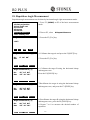
R2 PLUS
S-O dSD↓
↓
S-O dHA←
←
SD
VD
HA
5.251m
82.5440gon
149.3610gon
334.9916gon I
MEAS
MOKS
6. Horizontally rotate the instrument until “dHA” is
near 0 and set the target on the sight line.
Press F1: [MEAS] to start distance measurement.
7. The difference of measured and stake out value ”S-O
dSD” is displayed.
Move the prism forward and backward until “S-O
dSD” is 0m.
←: Move the prism left
→: Move the prism right
↓: Move the prism forward
↑: Move the prism backward
Press F4: [OK] back to stake out mode.
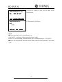
7.2 Coordinates Stake out Measurement
After setting coordinates for the point to be stake out, the instrument calculates the stake
out HA and HD. By selecting the HA and then the HD stake out functions, the required
coordinate location can be stake out.
To get the Z coordinate, attach the target to a pole etc, with the same target height.
N
Distanc
0
Back sight
station
Point to be
stake out
Instrument
station
Angle
E
【Procedure of coordinate stake out measurement】
】
Menu
1.Coordinate
2.Stake out
3.Area
4.Offset
5.MLM
6.REM
7.Resection
P1
1. Press F1: [MENU] at P2 in the measure mode.
Select “2. Stake out”.
2. Select “1. Occ. Orientation”.
Input the occupied orientation data, see Ҥ6.1
Input the occupied point data ”.
Then set the azimuth angle of the backsight point, see “§6.2 Azimuth setting”.
36
R2 PLUS
Stake out
1.Height
2.Angle & Dist
3.Coord
S-O
3. Select “2. S-O data”, then select “3.Coord”.
4. Input the coordinates of the stake out point.
Press F1: [READ] to read the existed coordinates
as stake out coordinate.
Press F4: [OK] to set the data.
Coord
Np:
Ep:
Zp:
Pt#
Tgt.H
READ
157.000
0.178
0.000
1.500m
R E C MOKS
↓
-147.328m
0.000m
19.310m
S-O dHD ↑ -147.328
S-O dHA→
→ 146.7194go
VA
296.1184gon I
HA
249.0324gon
MEAS NEXT
MOKS
5. Press F1: [MEAS] begin coordinate stake out
measurement. Move the prism to find the point to be
stake out.
: Move the prism upward
: Move the prism downward
Press key {ESC} back to stake out mode.
7.3 REM Stake out Measurement
Perform this operation to find a point where a target cannot be directly installed, see Ҥ
11 REM”.
】
【Procedure of REM stake out measurement】
S-O
1. JOB select
2. Occ. Orientation
3. EDM
4. S-O data
Stake out
1.Height
2.Angle & Dist
3.Coord
1. Set a target directly below or directly above the
point to be found, then use a measuring tape etc. to
measure the target height (height from the surveying
point to the target).
Press F1: [MENU] at P2 in the measure mode, then
select “2. Stake out”.
2. Select “2. Occ. Orientation”.
Input the occupied orientation data, see Ҥ6.1
Input the occupied point data ”.
3. Select “2. S-O data”, then select “1. Height”.
37
R2 PLUS
S-O Ht
Ht.
Tgt.H
2.000m
0.000m
4. Input height from the surveying point to the
position to be stake out. Then press F4: [OK] to set
the data.
MOKS
S-O Ht
SD
VA
HA
9.562
10.251m
79.6986gon
249.0404gon I
MEAS R E M
5. Press F1: [REM] to begin REM stake out
measurement. Move telescope to find the point to be
stake out.
: Move the telescope near the zenith
: Move the telescope near the nadir
Press key {ESC} back to stake out mode.
38
R2 PLUS
8. Area
Calculate an area shaped with several points. The coordinate data of the points could be
either measured or input by hand.
Input:
Output:
Coordinates: P1 (N1, E1)
Area:S
P2 (N2, E2)
P3 (N3, E3)
…
N
P3
P2
P4
S
P1
P5
E
0
NOTE:
◆ The number of points: 3 ~ 30.
◆ Make sure these points must be measured or listed clockwise or anticlockwise, or
mistake will result.
8.1 Area Calculation by Measured Data
【Procedure of area calculation】
】
Area
1.Occ.Orientation
2.Area
01:
02:
03:
04:
05:
06:
07:
READ
1. Select F2: [MENU]/ 3. Area /2.Area.
2. Aim at the first point, and then press F4: [MEAS].
MEAS
39
R2 PLUS
N
E
Z
VA
HA
10.000
5.000
53.493
152.6296gon
62.1314gon
0OK0
01:Pt_01
02:Pt_02
03:Pt_03
04:Pt_04
05:
06:
07:
CALC
3. Press F4: [MEAS] to re-measure distance or press
F1: [OK], the measured data is set as“Pt-01”.
MEAS
4. Repeat steps 2 and 3 till all points are measured one
by one. Make sure measure them clockwise or
anticlockwise. Press F2: [CALC] and the calculated
area will display.
MEAS
Area Calculation
Pt:
4
Area
m2
ha
5. Press F4: [OK] back to menu mode.
0OK0
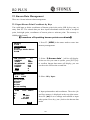
8.2 Area Calculation by Reading Existed Coordinates
【Procedure of area calculation】
】
Menu
1.Coordinate
2.Stakeout
3.Area
4.Offset
5.MLM
6.REM
7.Resection
01:
02:
03:
04:
05:
06:
07:
READ
P1
1. Select F2: [MENU]/ 3. Area /2.Area.
.
2. Press F1: [READ] to display existed coordinates
data list.
MEAS
40
R2 PLUS
Occ.
O1
Pt#
Pt1
Coord
C1
Pt#
Pt2
Pt#
Pt3
Pt#
Pt4
Pt#
Pt5
↑↓.P
↑↓ T O P LAST SRCH
3. Pt#: Known point data saved in the active JOB or in
the coordinate search JOB.
Occ./Coord: Coordinate data saved in the active
JOB or in the coordinate search JOB.
01:O1
02:Pt1
03:C1
04:Pt2
05:
06:
07:
READ CALC
4. Select the first point in the list and press key {ENT}
to set.
The selected point is set as “Pt-01”.
5. Repeat steps 2 and 4 till all points are selected.
Make sure read the points clockwise or
anticlockwise.
Area Calculation
Pt:
4
Area
m2
ha
6. Press F2: [CALC], and the calculated area will
display. Press F4: [OK] to escape.
0OK0
41
R2 PLUS
9. Offset Measurement
Offset measurement are performed in order to find a point where a target cannot be
installed directly or to find the distance and angle to a point which cannot be sighted.
It is possible to find the distance and angle to a point you wish to measure (target point)
by installing the target at a location (offset point) a little distance from the target point and
measuring the distance and angle from the surveying point to the offset point.
The target point could be found in the following three ways.
9.1 Single-distance Offset Measurement
Finding a point by entering the horizontal distance from the target point to the offset
point.
Target point
Offset point
(Target)
Instrument station
When the offset point is positioned to the left or right of the target point, make sure the
angle formed by lines connecting the offset point to the target point and to the instrument
station is almost 90°.
When the offset point is positioned in front of or behind the target point, installs the offset
point on a line linking the instrument station with the target point.
【Procedure of single-distance offset measurement】
】
Menu
1.Coordinate
2.Stake out
3.Area
4.Offset
5.MLM
6.REM
7.Resection
P1
1. Set the offset point close to the target point and
measure the distance between them, then set up a
prism on the offset point.
2. Aim at the offset point and press F1: [MEAS] to
measure the distance at P1 in measure mode.
42
R2 PLUS
Offset
1.Occ. Orientation
2.Offset/Dist
3.Offset/Angle
4.Offset/2Dist
Offset
1.Occ. Orientation
2.Offset/Dist
3.Offset/Angle
4.Offset/2Dist
Offset/Dist
SD
VA
HA
10.186m
90.0000gon
64.5154gon
II
MEAS
MOKS
Offset/Dist
Dist
Direc
10.000m
↓
MOKS
Offset/Dist
SD
VA
HA
13.511m
346.9636gon
249.0298gon
R E C N E Z M NOS Y E S
3. Select [MENU]/4. Offset, or press F3: [OFST] at
P3 of basic measurement menu.
4. Select “1. Occ. orientation” to input the
instrument occupied data, see “ § 6.1 Input the
occupied point data”.
5. Select “2. Offset/Dist”.
6. User could press F1: [MEAS] to re-measure the
offset point or press F4: [OK] to the next step.
7. Input distance and direction of offset point:.
① Dist: horizontal distance from the target point to
the offset point.
② Direc: direction of the offset point.
←: on the left of the target point
→: on the right of the target point
↓: in front of the target point
↑: at back of the target point
8. Press F4: [OK] to calculate and display the distance
and angle of the target point.
9. Press F1: [REC] to save;
Press F2: [NEZ] to display NEZ coordinate;
Press F3: [NO] back to step 6;
Press F4: [YES] back to offset mode.
43
R2 PLUS
9.2 Angle Offset Measurement
Sighting the direction of the target point to find it from the included angle. Set offset
points for the target point on the right or left sides of and as close as possible to the target
point and measure the distance to the offset points and the horizontal angle of the target
point.
Target point
Offset point
(Target)
Offset point
(Target)
Instrument station
【Procedure of angle offset measurement】
】
Menu
1.Coordinate
2.Stake out
3.Area
4.Offset
5.MLM
6.REM
7.Resection
P1
Offset
1.Occ. Orientation
2.Offset/Dist
3.Offset/Angle
4.Offset/2Dist
Offset/Angle
SD
VA
HA
10.186m
90.0000gon
64.5154gon
II
Aim at target?
MEAS
MOKS
1. Set the offset points close to the target point
(making sure the distance from the instrument station
to the target point and distance to the offset point are
same, the height of the offset points and the target
point are the same), then use the offset points as the
target.
2. Aim at the offset point and press F1: [MEAS] to
measure the distance at P1 in measure mode.
3. Select [MENU] at P2 in measure mode, and then
select “4. Offset”, or press F3: [OFST] at P3
directly.
4. Select “3. Offset/Angle” after inputting
instrument occupied data, see “ § 6.1 Input the
occupied point data”.
5. Accurately sight the direction of the target point
and press F4: [OK], the distance and angle of the
target point are displayed.
44
R2 PLUS
Offset/Ang
SD
VA
HA
13.511m
346.9636gon
249.0298gon
6. After finishing measurement:
Press F1: [REC] to save;
Press F2: [NEZ] to display NEZ coordinate;
Press F3: [NO] back to step 6;
Press F4: [YES] back to offset mode.
R E C N E Z M NOS Y E S
9.3 Dual-Distance Offset Measurement
By measuring the distance between the target point and the two offset points. Set two
offset points (1st target and 2nd target) on a straight line from the target point, measure
the 1st and 2nd target, then input the distance between the 2nd target and the target point
to find the target point.
Target point
Offset point
(Target)
Offset point
(Target)
Instrument station
【Procedure of dual-distance offset measurement】
】
Menu
1.Coordinate
2.Stake out
3.Area
4.Offset
5.MLM
6.REM
7.Resection
Offset
1.Occ. Orientation
2.Offset/Dist
3.Offset/Angle
4.Offset/2Dist
P1
1. Set two offset points (1st target, 2nd target) on a
straight line from the target point and use the offset
points as target.
2. Select [MENU] at P2 in measure mode, and then
select “4. Offset”, or press F3: [OFST] at P3 directly.
3. Select “4. Offset/2Dist” after inputting the
instrument occupied data, see “ § 6.1 Input the
occupied point data”.
45
R2 PLUS
Observe 1st offset
N
E
Z
VA
HA
MEAS
10.186
10.000
10.000
90.0000gon
64.5154gon
MOKS
Observe 2nd offset
N
E
Z
VA
HA
MEAS
Dist
10.186
10.000
10.000
90.0000gon
64.5154gon
MOKS
5. Sight the 2nd target, press F1: [MEAS] and
measured data will display, press F4: [OK] to accept
this value.
6. Input the distance from 2nd point to the target point
and press key {ENT}, the angle and distance of the
target point are displayed.
123456789m
Offset/2Dist
SD
VA
HA
4. Aim at the 1st target and press F1: [MEAS] and
measured data will display. Press F4: [OK] to accept
this value.
13.511m
346.9636gon
249.0298gon
7. Press F1: [REC] to save;
Press F2: [NEZ] to display NEZ coordinate;
Press F3: [NO] back to step 6;
Press F4: [YES] back to offset mode.
R E C N E Z M NOS Y E S
46
R2 PLUS
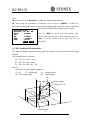
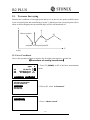
10. MLM
MLM is used to directly measure slope distance, horizontal distance and the height
difference from one base point to other points without moving the instrument.
NOTE:
◆ The last measured data could be set as the base point for the next starting operation.
◆ The height difference between one point and the base point could be displayed as
grade mode.
H2
S2
V2
%2
H1
V1
S1
%1
Target (P3)
Target (P2)
Start point (P1)
Occupied point
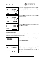
10.1 Measuring Distance between Two or More Points
【Procedure of measuring】
】
Menu
1.Coordinate
2.Stakeout
3.Area
4.Offset
5.MLM
6.REM
7.Resection
1. Press F2: [MENU] at P2 in the measure mode.
Select “5. MLM”.
P1
MLM
SD
HD
VD
33.421ft
155.6594gon
355.9246gon
I
M L M MOVE
2. Aim at the start point P1, then press F4: [MEAS]
and the measured data will display.
3. Aim at the target point P2 and press F1: [MLM] to
begin measure, SD, HD, VD will display.
MEAS
47
R2 PLUS
MLM
S/%
SD
HD
VD
%
M L M MOVE
MEAS
I
4. Aim at the next point P3 and press F1: [MLM] to
begin measure. Repeat this operation to measure other
target points.
5. Press F2: [MOVE], the last target measured
becomes the new starting position to perform MLM of
next target.
Press F4: [MEAS] to re-measure the starting
position.
6. Press key {ESC} back to menu mode.
Note:
◆ Once “S/%” is displayed, the distance between two points is displayed as the gradient
10.2 Change the Starting Point
The previous measured data could be set as the base point for the next operation.
H2
%2
V2
S2
H1
V1
S1
%1
Point (P3)
Point (P2)
Start point (P1)
【Procedure of changing the starting point】
】
MLM
Move base point?
SD
-0.001m
VA
368.3854gon
HA
243.4068gon
MNOS Y E S
1. Measure the start point P1 and the first target P2
following above steps 1, 2 and 3.
2. After measuring the two points, press F2: [MOVE],
and press F4: [YES] to set the last measured point as
new starting point, or press F3: [NO] to give up.
48
R2 PLUS
11. REM
REM is a function used to measure the coordinate and height to a point where a target
cannot be directly installed such as power lines, overhead cables or bridges, etc.
Target point B
α2
H2
S
Ht
α1
H1
B’
Here is the equation used to calculate the data presented in above figure:
Ht=H1+Scosα1tgα2-Ssinα1
【Procedure of REM】
】
Menu
1.Coordinate
2.Stake out
3.Area
4.Offset
5.MLM
6.REM
7.Resection
P1
REM
Need prism obs
SD
HD
VD
I
REM
REM
Ht.
SD
HD
VD
3. Reference point measurement.
Aim at the prism accurately, and press F4: [MEAS] to
measure distance. Press F4: [STOP] and the measured
data are displayed. Press F4: [MEAS] to re-measure.
MEAS
1.518ft
33.421ft
0.000ft
15.790ft
I
REM
1. Set a target directly under or directly over the object
and measure the target height with a tape measure etc.
2. Press F2: [MENU] on P2 of the basic measurement
mode, then select “6.REM” on P1 to enter into REM
status.
4. Aim at the target accurately and press F2: [REM].
The height from ground to the target is displayed in
“Ht”. Press F4: [MEAS] to repeat and press key {ESC}
back to menu mode.
MEAS
49
R2 PLUS
12. Resection
Resection program is used to determine the coordinates of an instrument station
(unknown) by measuring several known points. Coordinate data in memory could be read.
Input
Coordinates of known points: Xi, Yi, Zi
Measured HA: Hi
Measured VA: Vi
Measured distance: Di
Output
Coordinate of occupied data: Xo, Yo, Zo
Known point P1
Known point P2
Occupied point P0
Known point P4
Known point P3
NOTE:
◆ All N, E, Z value or only Z value of the occupied point is calculated by measuring
known points.
◆Coordinate resection measurement overwrite the N, E, Z data of the instrument
occupied point, while elevation resection measurement overwrite Z data only. Perform
resection measurement, see “§ 12.1 Coordinate Resection” and “§ 12.2 Elevation
Resection”.
◆Inputted known coordinate data and calculated data could be recorded in the current
JOB.
50
R2 PLUS
12.1 Coordinate Resection
Between 2 and 5 known points can be measured by distance measurement and angle
measurement.
【Procedure of coordinate resection】
】
Menu
1.Coordinate
2.Stake Out
3.Area
4.Offset
5.MLM
6.REM
7.Resection
1. Select [MENU] at P2 of basic measurement mode,
and then select “7. Resection”, or select [RES] at P3
directly.
Resection
1.NEZ
2.Elevation
2. Select “1.NEZ” and input known point data. After
inputting the data of the first known point, press F3:
[NEXT] to input the second point data.
No. 1Pt#
Np:
Ep:
Zp:
Pt#
Tgt.H
READ R E C NEXT MEAS
Resection
No.1PT
3. After all known points data have been set, press F4:
[MEAS].
Press F1: [READ] to read existed coordinate data.
4. Sight the first known point and press F1: [DIST] to
begin measurement. If known points number is more
than two, F2: [ANG] will display, you can confirm the
known point by angle measurement.
N
E
Z
Pt#
DIST ANG
Resection
SD
VA
HA
Tgt.H
No.1Pt
10.188m
189.9284gon
47.2432gon
000000m
I
TNOT Y E S
5. Press F4: [YES] to use the measured data of the
first known point.
Press F3: [NO] to re-measure this point.
You can also input target height here.
51
R2 PLUS
Resection
SD
VA
HA
Tgt.H
No.2Pt
10.188m
189.9284gon
47.2432gon
m
CALC
I
TNOT Y E S
Occ. Coord
N
E
Z
dN
dE
NEXT DISP R E C TOKT
Resection
Set Azimuth
TNOT Y E S
6. Repeat procedures 4 and 5 of other points.
When the minimum quantity of measured data
required for the calculation is present, [CALC] will be
displayed.
Press F1: [CALC] to calculate. Instrument
occupied coordinate and standard deviation are
displayed.
Press F3: [NO] to re-measure the point.
7. Press F1: [NEXT] to add other known points.
Press F2:[DISP] to view the tolerance of measured
known points
Press F3: [REC] to record the calculated result.
Press F4: [OK] to finish coordinate resection.
The instrument occupied coordinate setting is
finished.
8. In this <Set Azimuth> screen, aim the first point
then press F4: [YES] to set the first known point as
backsight point and azimuth, press F3: [NO] to back
to measure mode.
12.2 Elevation Resection
Only Z (elevation) of an instrument station is dertermined by this measurement. Between
1 and 5 known points can be measured by distance measurement only.
【Procedure of elevation resection】
】
Menu
1.Coordinate
2.Stake Out
3.Area
4.Offset
5.MLM
6.REM
7.Resection
Resection
1.NEZ
2.Elevation
1. Press F2: [MENU] on P2 of the basic measurement
mode, and then select “7. Resection”, or press F4:
[RES] at P3 directly.
2. Select “2. Elevation” and input the known point.
52
R2 PLUS
No. 1Pt#
Z
Pt#
Tgt.H
READ R E C NEXT MEAS
Resection
5. Sight the first known point and press F1: [DIST] to
begin measurement. The measured data are displayed.
No.1PT
Z
Pt#
6. Press F4: [YES] to use the measured data of the first
DIST
Resection
SD
VA
HA
Tgt.H
No.1Pt
10.188m
189.9284gon
47.2432gon
000000m
CALC
I
TNOT Y E S
Occ.Coord
Z
dZ
NEXT
3. After setting the elevation for the first known point,
press F3: [NEXT] to set the second point data.
4. After all known points data have been set, press F4:
[MEAS].
Press F1: [READ] to read existed coordinate data.
R E C TOKT
known point data.
Press F3: [NO] to re-measure the point. You can
also input target height here.
After finishing two measurements, [CALC] will be
displayed.
6. Press F1: [CALC] to calculate. Instrument occupied
elevation and standard deviation are displayed.
7. Press F1: [NEXT] to add other known points.
Press F3: [REC] to record the calculated result.
Press F4: [OK] to finish elevation resection. Only Z
(elevation) of the instrument occupied coordinate is
set. N and E values would not be overwritten.
53
R2 PLUS
12.3 Resection Calculation Process
The N, E coordinates are found by angle and distance measurement equations, and the
instrument occupied coordinates are found using the least squares method. The Z
coordinate is found by treating the average value as the instrument occupied coordinate.
Calculation begins
Hypothetical coordinates are found
The measured equation for the angle is prepared
The measured equation for the distance is prepared
Iterate 3 times
▼
The normal equation is prepared
Instrument occupied coordinates are calculated
▼
Difference from the hypothetical
coordinates ≦ 0.5mm
Yes
Calculation of the Z coordinate
Calculation ends
54
No
R2 PLUS
12.4 Precautions When Performing Resection
In some cases it is impossible to calculate the coordinates of occupied point if the
unknown point and three or more known points are arranged on the edge of a single circle.
It is also impossible to calculate if the included angle between the known points is too
small. It is difficult to imagine that the longer the distance between the instrument
occupied and known points, the narrower the included angle between the known points.
Be careful for the points can easily be aligned on the edge of a single circle.
An arrangement such as shown below is desirable.
△▲:unknown point
○●:known point
It is sometimes impossible to perform a correct calculation such as shown below.
When they are on the edge of a
single circle, take one of the following methods:
(1) Move the instruction station as close
as possible to the center of the triangle.
(2) Measure one more known point which
is not on the circle.
(3) Perform a distance measurement on at
least one of the three points.
55
R2 PLUS
13. Point Projection
Point projection is used for projecting a point to an established baseline. The point to
project can be either measured or input. Displays the distances from the first point and
point to project to the position at which a line extending from point to project intersects
the baseline at right angles.
Y direction
X direction
Baseline
1st Pt
2nd Pt
Offset
Length
Point to project
Length: Distance along the baseline from 1st point to 2nd point (X direction).
Offset: Distance from point to project to the position at which a line extending from point
of project intersects the baseline at right angles (Y direction).
13.1 Define Baseline
【Procedure of defining baseline】
】
Menu
1.Point projection
2.Stake out line
3.Traverse
4.Inverse
5.Polarize
6.Repeat Measure
7.Arc staking out
P2
1. Press F2: [MENU] at P2 of basic measurement
mode.
2. Turn to P2, select “1. Point projection”.
56
R2 PLUS
Point projection
1.Occ. Orientation
2.Define baseline
3.Point projection
Point projection
1.Occ. Orientation
2.Define baseline
3.Point projection
Define 1st Pt.
Np:
Ep:
Zp:
Pt#:
0.000
0.000
0.000
3. Input the instrument occupied data, see Ҥ6.1 Input
the occupied point data”.
4. Select “2. Define baseline”.
5. Input the first point data, or press F1: [READ] to
use existed coordinates data, or press F3:[MEAS] to
measure the point.
READ R E C M E A S OK
Define 2nd Pt.
Np:
Ep:
Zp:
Pt#:
6. Press F4: [OK] to input the second point data.
0.000
0.000
0.000
READ R E C M E A S OK
7. Press F4: [OK] to finish defining baseline. The
grade of the baseline will display.
Azimuth
HD
Grade
8. Press F2: [1:**] or F3: [%] to change the grade
300gon
10.412m
1:150
display mode.
1:
:** 0 %0 HOKD
NOTE:
◆ Defined baseline could be used in both stake out line measurement and point
projection.
57
R2 PLUS
13.2 Point Projection
The baseline must be defined before performing point projection.
【Procedure of point projection】
】
Point projection
1.Occ. Orientation
2.Define baseline
3.Point projection
Point projection
Np:
Ep:
Zp:
Pt#:
0.000
0.000
0.000
P1
HOKD
READ MEAS
Point projection
Length
Offset
dVD
NEZ REC
1385.260m
-203.107m
2.212m
S-O
1. Select “3. Point projection” after finishing
defining baseline.
2. Input the point coordinate.
Press F2: [MEAS] to measure the point to project.
When recording the data as a known point, press
key {Func}, and press F2: [REC] on P2. Record
method, see Ҥ 23.1 Input Known Point Coordinate
by Keys”.
3. Press F4: [OK] to calculate Length, Offset and dVD
will display.
Length: Distance along the baseline from 1st point
to 2nd point (X direction).
Offset: Distance from point to project to the
position at which a line extending from point of
project intersects the baseline at right angles (Y
direction)
dVD: Elevation between the baseline and the
projected point.
Press F1: [NEZ] to display switching between coordinate and distance data.
Press F2: [REC] to record the coordinate as a known data.
Press F4: [S-O] to switch to stake out measurement of the projected point. See “6 Stake
out measurement”.
Press key {ESC} to continue point projection of a new point.
58
R2 PLUS
14. Stake out Line
Stake out line is used for stake out a required point at a designed distance from the base
line and for finding the distance from the baseline to a measured point.
2nd Pt
Z
Cut
Grade
Fill
1stPt
Offset
E
Baseline
Azimuth Length
N
14. 1 Define Baseline
【Procedure of defining baseline】
】
To perform stake out line, please define a baseline first. The baseline can be defined by
inputting coordinates of the two points.
1. Press F2: [MENU] on P2 of the basic measurement
Menu
P2
mode.
1.Point projection
2.Stake out line
3.Traverse
4.Inverse
5.Polarize
6.Repeat Measure
7.Arc staking out
Stake out line
1.Occ. Orientation
2.Define baseline
3.Stake out line
2. Turn to P2, select “2. Stake out line”.
3. Input the instrument occupied data, see Ҥ6.1 Input
the occupied point data”.
4. Select “2. Define baseline”, following operations
see “§13.1 Define baseline” procedures 5, 6 and 7.
14. 2 Stake Out Line-Point
This measurement can be used to find the required point coordinates by inputting the
length and offset based on baseline.
59
R2 PLUS
Y direction
X direction
Baseline
1st Pt
2nd Pt
Offset
Length
Required point
Length: Distance along the baseline from 1st point to the position at which a line
extending from the required point intersects the baseline at right angles (X direction)
Offset: Distance from the required point to the position at which a line extending from the
required point intersects the baseline at right angles (Y direction).
【Procedure of stake out】
】
1.
Select
“
3.
Stake
out
line” after defining a
Stake out line
1.Occ. Orientation
baseline.
2.Define baseline
3.Stake out line
2. Select “1. Point”
Stake out line
1.Point
2.Line
Stake out line
3. Input values of length and offset, then press F4:
[OK], the coordinate of the required point is calculated
and displayed.
Length
Offset
HOKD
60
R2 PLUS
Stake out line
Np:
Ep:
Zp:
0.000
0.000
0.000
REC S-O
4. Press F3: [REC] to record the value as a known
point, see Ҥ20.1 Input Known Point Coordinate
by Keys”.
Press F4: [S-O] to stake out the required point,
see “§7. Stake out Measurement”.
Press key {ESC} to continue.
14.3 Stake out Line/Line
Stake out line-line tells how far horizontally the measured point is from the baseline and
how far vertically the measured point is from the connected line. Make sure to define a
baseline before this operation.
Measured point
Offline (-)
Length
Offset (horizontal direction)
Profile view
Measured point
2nd Pt
Cut
1st Pt
Offline: A positive value indicates the point is on the right of the baseline and a negative
value indicates it is on the left.
Cut: indicates that the point is below the baseline.
Fill: indicates that the point is above the baseline.
Length: distance along the baseline from 1st point to the measured point.
61
R2 PLUS
【Procedure of stake out line/line】
】
Stake out line
1.Occ. Orientation
2.Define baseline
3.Stake out line
2. Select “2.Line”.
Stake out line
1.Point
2.Line
Stake out line
Offset
MEAS
Stake out line
SD
33.417ft
VA
300.9994gon
I
HA
44.6568gon P2
Tgt.H
HNOT Y E S
Stake out line
Ofline
Fill
Length
1. Select “3. Stake out line” after defining a
baseline.
-0.995m
14.401m
3.993m
R E C MEAS
3. Input offset value: the horizontal move distance of
baseline, right side indicates positive value and left
side indicates negative value. Go to step 4 without
inputting.
4. Aim at the target and press F4: [MEAS] to measure.
The measured results are displayed.
5. Press F3: [NO] to re-measure the target.
Press F4: [YES] to use the measured values. The
difference between the measured data and the baseline
displays:
Ofline: A positive value indicates the point is on the
right of the baseline and a negative value indicates it
is on the left.
“Cut” indicates that the point is below the baseline.
“Fill” indicates that the point is above the baseline.
Length: Distance along the baseline from the first
point to the measured point.
6. Aim at the next target and press F4: [MEAS] to
continue the measurement.
62
R2 PLUS
15. Traverse Surveying
Measure the coordinate of foresight point and save it in the list, this point would be taken
as the occupied point after transferring to point 2, and the previous occupied point will be
taken as the backsight point, the azimuth angle will be calculated and set.
N
Known point A
P3
P1
P2
Occupied point P0
Azimuth
E
(0,0,0)
15.1 Save Coordinate
Here is the operation of how to measure the foresight point and save it in the list.
【Procedure of saving coordinate】
】
Meas
SD
VA
HA
PC
ppm
0
0
33.417ft
300.9994gon
I
44.6568gon P2
1. Press F2: [MENU] on P2 of the basic measurement
mode.
MENU HOLD HSET E D M
Menu
1.Point projection
2.Line stakeout
3.Traverse
4.Inverse
5.Polarize
P2
2. Turn to P2, select “3.Traverse”.
Traverse
1.Save coord
2.Read coord
3. Press “1.Save coord”.
63
R2 PLUS
3. Aim at the target point and then press F1: [DIST].
You can press F4: [I.HT] to re-input instrument height
or target height here.
Save coord
VD
VA
HA
29.183ft
315.3212gon
64.5876gon
I
DIST
I.HT
4. Press F4: [SET] to save the data, or press F3: [REC]
to record it in the list.
Save coord
VD
VA
HA
19.682ft
159.9150gon
68.0594gon
I
MEAS
REC SET
Save coord
N
E
Z
5.000
5.000
29.877
5. Press F3: [NO] back to the previous mode and press
F4: [YES] to set the data.
> Set?
0NO0 Y E S
15.2 Read Coordinate
Set the measured foresight point in the saved coordinates list as the occupied point, and
the previous occupied point becomes the back point.
Traverse
1.Save coord
2.Read coord
1. Move the instrument to the measured forsight point.
2. Select “2. Read coord”.
Read coord
HA
-0.0002gon
> Set?
3. First aim the previous occupied point, then press F4:
[YES] to set the previous foresight point coordinate as
the occupied point coordinate or press F3: [NO] to
give up.
0NO0 Y E S
64
R2 PLUS
16. Inverse
The distance and azimuth from a start point to an end point could be calculated according
to input their coordinates.
Input:
Output:
Coordinate of start point: N0,E0,Z0
Distance: D
Coordinate of end point : N1,E1,Z1
Azimuth: Az
【Procedure of Inversing】
】
Menu
1.Point projection
2.Line stakeout
3.Traverse
4.Inverse
5.Polarize
6.Repeat Measure
7.Arc staking out
P2
Coord Inverse
Start point
N
1000.000
E
1000.000
Z
39.383
Pt#
READ
3. Input coordinates of the start point, and press F3:
[REC] to record the data in the list if necessary. You
could press F1: [READ] to read the existed data. Press
F4: [OK] to set.
4. Input coordinates of the end point. See the previous
step.
R E C 0OK0
Coord Inverse
Azimuth
HD
VD
2. Turn to P2, select “4.Inverse”.
R E C 0OK0
Coord Inverse
End point
N
1000.000
E
1000.000
Z
10.000
Pt#
READ
1. Press F2: [MENU] on P2 of the basic measurement
mode.
-0.0002gon
0.000ft
-29.383ft
5. The inversed value will display. Press F3: [NEXT]
to continue, press F4: [OK] back to menu mode.
NEXT 0OK0
65
R2 PLUS
17. Polar Coordinates Calculation
The coordinates of the end point could be calculated according to input azimuth, distance
and the NEZ coordinates of start point.
Input:
Coordinate of start point: N0,E0,Z0
N
Azimuth: Az
Distance: Dist
Output:
End point
Coordinate of end point:N1,E1,Z1
Az
D
Start point
【Procedure of Polarize】
】
Menu
1.Point projection
2.Line stake out
3.Traverse
4.Inverse
5.Polarize
6.Repeat Measure
7.Arc staking out
P2
Calc polar coord
Pt#
C1
N
1000.000
E
1000.000
Z
39.383
Azimuth
1.0000gon
Dist
0.000ft
READ
0OK0
Calc polar coord
N
E
Z
0OK0
1000.000
1000.000
0.000
1. Press F2: [MENU] on P2 of the basic measurement
mode.
2. Turn to P2, select “5.Polarize”.
3. Input the data in corresponding items. You could
press F1: [READ] to read the existed coordinate data
for start point. Press F4: [OK] to enter.
4. The calculated data displays. Press F3: [REC] to
record it in the list, and press F1: [OK] back to menu
mode.
REC
66
R2 PLUS
18. Repetition Angle Measurement
Repetition angle measurement can be done by horizontal angle right measurement mode.
1. Press F2: [MENU] on P2 of the basic measurement
Menu
P2
1.Point projection
mode.
2.Line stake out
3.Traverse
4.Inverse
5.Polarize
6.Repeat Measure
7.Arc staking out
2. Turn to P2, select 6.Repeat Measure.
3. Press the F3:[Yes] key.
Angle Remeasure
>OK?
----
----
YES
NO
Angle Remeasure
Ht:
Hm:
[0]
0°
°00′
′00″
″
4. Collimate the target A and press the F1[0SET] key.
5. Press the F3:[Yes] key.
0SET MEAS FREE H O L D
Angle Remeasure [1]
Ht:
Hm:
45°
°10′
′00″
″
45°
°10′
′00″
″
6. Collimate the target B using the horizontal clamp
and tangent screw.
Press the F4:[HOLD] key.
0SET MEAS FREE H O L D
Angle Remeasure [1]
Ht:
Hm:
7.Recollimate the target A using the horizontal clamp
and tangent screw, and press the F3:[FREE] key.
45°
°10′
′00″
″
45°
°10′
′00″
″
0SET MEAS FREE H O L D
Angle Remeasure [2]
Ht:
Hm:
90°
°20′
′00″
″
45°
°10′
′00″
″
0SET MEAS FREE H O L D
8. Recollimate the target B using the horizontal clamp
and tangent screw, press the F4:[HOLD] key.
9. Repeat 7 to 8 to measure the desired number of
repetition.
67
R2 PLUS
Angle Remeasure [4]
Ht:
Hm:
180°
°40′
′00″
″
45°
°10′
′00″
″
10. Press F2: [Meas] or [ESC] key to return to the
normal mode.
0SET MEAS FREE H O L D
11. Press the F3:[YES] key.
Angle Remeasure
Exit
>OK?
----
----
YES
NO
NOTE:
● Horizontal angle can be accumulated up to
(3600°00'00" – minimum reading) (horizontal angle right).
In case of 5 second reading, horizontal angle can be accumulated up to +3599°59'55".
● Error will be displayed when the results differ from first measurement by more than
±30".
68
R2 PLUS
19. Arc Staking Out Measurement
Stake out a designed arc by arc staking out measurement, see below figure, after define
the arc by 2points-arc or 3points, the instrument will help you move the rod to the arc.
Here:
S.P– Start point of arc
E.P– End point of arc
C.P– Circle center point of arc
Station(from S.P to A) - the station on the arc computed radially from the current
position of the prism.
Offset(from rod to B) – offset distance from the current position to the arc.
S-O dHA – If your line of sight does not intersect the arc, it will display to ask you rotate
you telescope until sight line intersect the arc, and then In/Out will display. Offset angle
is from the current position to the arc
Fill/Cut – Cut value indicate that the rod is higher than the arc, fill indicates the it is
lower
In/Out(from Rod to A)– This is the distance you need to move in out to get to the arc.
69
R2 PLUS
19.1 Two Point Arc Staking Out
1. Press F2: [MENU] on P2 of the basic measurement
mode, select 7.Arc Staking out to enter arc staking
out menu, select 1.Occ.Orientation to set the station.
And then select 2. 2pt+radius arc to start 2-point arc
staking out measurement.
Arc Stakeout
1.Occ.Orientation
2.2pt+radius arc
3.Three Point arc
2. Input the coordinate of arc start point.
Define/Start PT
Pt#
Np:
Ep:
Zp:
Press F1[READ] to read the existed coordinate as
stake out coordinate
Press F4:[OK] to set the data.
J2
11.829
0.000
1.846
READ R E C MEAS
OK
3. Input the coordinate of arc end point.
Press F1[READ] to read the existed coordinate as
stake out coordinate
Press F4:[OK] to set the data.
Define/End PT
Pt#
Np:
Ep:
Zp:
J3
11.282
-2.130
1.503
READ R E C MEAS
OK
Arc define/Rad Input
Rad
100.000
OK
Are stake out/Measure
Stn :
Offset:
S-O
dHA
Fill:
MEAS
4. Input the radius of arc, press F4:[OK] to set the
data.
2.930m
8.304m
12 27 49
1.545
OK
5. Press F1:[MEAS] to measure current rod, the
staking date will display.
Station - the station on the arc computed radially
from the current position of the prism.
Offset – offset distance from the current position to
the arc.
S-O dHA – offset angle from the current position to
the arc
Fill/Cut – Cut value indicate that the rod is higher
than the arc, fill indicates the it is lower
In/Out– This is the distance you need to move in out
to get to the arc.
70
R2 PLUS
Are stake out/Measure
Stn :
Offset:
In:
Fill:
1.112m
0.013m
0.013m
0.306m
MEAS
6. According the S-O dHA angle to move the rod until
the telescope sight intersect the arc.
OK
Are stake out/Measure
Stn :
Offset:
In:
Fill:
1.109m
0.003m
0.003m
0.006m
MEAS
7. Repeat moving and measuring the rod until all the
stake data are accepted. Press F4: [ESC] to escape this
program.
OK
19.2 Three Point Arc Staking Out
1. Press F2: [MENU] on P2 of the basic measurement
mode, select 7.Arc Staking out to enter arc staking
out menu, select 1.Occ.Orientation to set the station.
And then select 3.Three point arc to start three-point
arc staking out measurement.
Arc Stakeout
1.Occ.Orientation
2.2pt+radius arc
3.Three Point arc
2. Input the coordinate of arc start point.
Define/Start PT
Pt#
Np:
Ep:
Zp:
Press F1[READ] to read the existed coordinate as
stake out coordinate
Press F4:[OK] to set the data.
J1
0.000
0.000
0.000
READ R E C MEAS
OK
3. Input the coordinate of arc end point.
Define/End PT
Pt#
Np:
Ep:
Zp:
Press F1[READ] to read the existed coordinate as
stake out coordinate
Press F4:[OK] to set the data.
J2
11.282
-2.130
1.503
READ R E C MEAS
OK
71
R2 PLUS
4. Input the coordinate of arc middle point.
Define/Mid PT
Pt#
Np:
Ep:
Zp:
Press F1[READ] to read the existed coordinate as
stake out coordinate
Press F4:[OK] to set the data.
J5
3.027
-0.685
0.305
READ R E C MEAS
OK
Are stake out/Measure
Stn :
Offset:
S-O
dHA
Fill:
MEAS
0.015m
115.491m
5 16 17
1.541
OK
Are stake out/Measure
Stn :
Offset:
In:
Fill:
MEAS
0.015m
10.025m
0.013m
0.306m
OK
5. Press F1:[MEAS] to measure current rod, the
staking date will display.
Station - the station on the arc computed radially
from the current position of the prism.
Offset – offset distance from the current position to
the arc.
S-O dHA – offset angle from the current position to
the arc
Fill/Cut – Cut value indicate that the rod is higher
than the arc, fill indicates the it is lower
In/Out(from Rod to A)– This is the distance you
need to move in out to get to the arc.
Are stake out/Measure
Stn :
Offset:
In:
Fill:
MEAS
0.012m
0.003m
0.003m
0.006m
OK
6. According the S-O dHA angle to move the rod until
the telescope sight intersect the arc.
7. Repeat moving and measuring the rod until all the
stake data are accepted. Press F4: [ESC] to escape this
program.
72
R2 PLUS
20. Road Staking Out Measurement
This program is especially designed for Road Layout measurement. It can be used for
horizontal curve layout. Normally one road is constituted by several elements, such as
line, circle curve or Spline.
Menu
P3
1.Road Calculation
H road elements list
Input Start station
Type EndPile
Select 1
1
Road Calculation
1.Input the parameter
2.Road Setout
3.Road file
HCurve/Start Point
STATION: 0.000
Np :
0.000
Ep :
0.000
Zp :
0.000
0OK0
DEL LINE CIR CURV
Line Input/LENGTH
F2
Dist
0.000m
Azimuth 0°00′00″
StartPine Height
1
Road Define
1.Horizontal Curve
2.Vertical curve
3.Road Calculation
ENDP ENT
2
F3
TOP LAST DEL ADD
RoadCal/Calc
2
3
Road Setiyt
1.Occ.Orientation
2.Road Setout
3.Road data view
3
STATION: 0.000
SPAC
10.000
WIDE PEG
ENT
F4
Road File Select
1.Road File Select
2.Road File Rename
3.Road File Delete
4.Road Initialize
Circle Input
Dist
0.000m
Rad
0.000m
Azimuth 0°00′00″
Turn
LEFT
ENT
Spiral Input
Dist
0.000m
Rad
0.000m
Azimuth 0°00′00″
Turn
LEFT
Direction IN
ENDP ENT
Clear all roads?
4
1
2
Road File Select
ROAD1
ROAD2
ROAD3
ROAD4
ROAD5
0
0
0
0
0
Road File Rename
ROAD1
73
3
Road File Select
ROAD1
0
ROAD2
0
ROAD3
0
ROAD4
0
ROAD5
0
R2 PLUS
20.1 Input the Start Station
Road Calculation
1.Road file
2.Input the parameter
3.Road Setout
Road Define
1.Horizontal Curve
2.Vertical curve
3.Road Calculation
HCurve/Start Point
STATION: 0.000
Np :
0.000
Ep :
0.000
Zp :
0.000
1. Press F2: [MENU] on P2 of the basic measurement
mode, on the page 3 select 2.Road Calculation enter
road menu.
2. Select 1.Input the parameter to enter road design
menu. And then select 1.Horizontal Curve, start
point entering menu will display.
3. Enter the start point station and coordinate, press
F4:[OK] key. Road horizontal elements editing menu
will display.
0OK0
Type EndPile
DELv LINEv CIR
CURV
20.2 Input Road Horizontal Elements
Three types elements can be input, including line, curve and spiral.
20.2.1 Input Line Element
Line Input/LENGTH
Dist
100m
Azimuth 0°°00′′00″″
ENDP
1. Make sure the instrument is in horizontal elements
editing menu, press F2 to display line element
inputting menu.
Input the line length and azimuth in the Dist and
Azimuth filed.
ENT
74
R2 PLUS
Press F4:[ENT] key to confirm.
NOTE:
Line Input/END POINT
Pt#
N
E
Z
READ
100m
0.000m
0.000m
You can press F3:[ENDP] to enter the end point
inputting menu.
Input the end point coordinate directly, or press
F1:[READ] to recall from memory.
Press F3:[LINE] to back to the LENGTH menu
LINE ENT
Type EndPile
Line 100.000
Press F4:[ENT] to confirm, you will see the line
element in the list menu.
Here EndPile means the end station of this element.
DEL LINE CIR CURV
20.2.2 Input Circle Element
CIRCLE INPUT
Dist
100.000m
Rad
100.000m
Azimuth 0°°00′′00″″
Turn
RIGHT
1. Make sure the instrument is in horizontal elements
editing menu, press F3 to display curve element
inputting menu.
Input the curve parameters, including length[Dist],
radius[Rad], azimuth[Azimuth] and turn [Turn].
ENT
Type EndPile
Line 100.000
Circle 200.000
2. Press F4:[ENT] key to confirm, back to the
horizontal elements menu.
Here EndPile means the end station of this element.
DEL LINE CIR CURV
NOTE:
1. Normally the azimuth will calculate and display following previous element.
2. When you set the turn, move the cursor to [Turn] item, press ◄ or ► key to shift
between Left and Right.
75
R2 PLUS
20.2.3 Input Spiral Element
Spiral Input
Dist
100.000m
Rad
100.000m
Azimuth 57°°17′′44″″
Turn
RIGHT
Direction
IN
ENT
Type
Line
Circle
Spiral
EndPile
100.000
200.000
300.000
1. Make sure the instrument is in horizontal elements
editing menu, press F4 to display spiral element
inputting menu.
Input the curve parameters, including length[Dist],
radius[Rad], azimuth[Azimuth], turn [Turn] and
direction[Direction].
2. Press F4:[ENT] key to confirm, back to the
horizontal elements menu.
Here EndPile means the end station of this element.
DEL LINE CIR CURV
NOTE:
1. Normally the azimuth will calculate and display following previous element.
2. When you set the turn or direction, move the cursor to [Turn] or [Direction]item, press
◄ or ► key to shift the options.
3. If you set the Direction is IN, here the inputted Rad is End radius of spiral, its start
radius is default as ∞; if you set the direction is OUT, here the inputted is start radius of
spiral, its end radius is default as ∞.
20.2.4 Road Horizontal Element Editing
In the horizontal element editing menu, the inputted element can be edited.
Type
EndPile
Line
100.000
Circle
200.000
Spiral
300.000
Circle
400.000
Spiral
500.000
Line
600.000
DEL LINE CIR CURV
Type
EndPile
Line
100.000
Circle
200.000
Spiral
300.000
Circle
400.000
Spiral
500.000
Line
600.000
DEL LINE CIR CURV
● Delete horizontal element
1. Move ▲ or ▼ key, the cursor will move to
different element.
2. Press F1:[DEL] to delete the selected element, the
two elements adjacent with deleted one will connect
automatically.
76
R2 PLUS
Type
Line
Spiral
Circle
Spiral
Line
EndPile
100.000
200.000
300.000
400.000
500.000
DEL LINE CIR CURV
● Edit horizontal element
Type
Line
Spiral
Circle
Spiral
Line
EndPile
100.000
200.000
300.000
400.000
500.000
1. Move ▲ or ▼ key, the cursor will move to
different element.
DEL LINE CIR CURV
Line Input/CIRCLE
2. Press ENT key to edit the selected element.
Dist
200.000m
Rad
100.000m
Azimuth 0°°00′′00″″
Turn
RIGHT
Direction
IN
ENT
Type
Line
Spiral
Circle
Spiral
Line
EndPile
100.000
300.000
400.000
500.000
600.000
3. Press F4:[ENT] key to confirm, other elements
following the edited one will upgrade automatically.
DEL LINE CIR CURV
Road Define
1.Horizontal Curve
2.Vertical curve
3.Road Calculation
4. After all the horizontal elements are confirmed,
press [ESC] key back to previous menu.
77
R2 PLUS
20.3 Input Road Vertical Elements
Road vertical elements is confirmed by some intersection points, you should input same
parameters for the intersection points, including station, height, and length from this
intersection point to next intersection point.
20.3.1 Input Vertical Road Element.
Road Define
1.Horizontal Curve
2.Vertical curve
3.Road Calculation
StartPile
FIST LAST
Height
DEL
1. Make sure the instrument is in Road Define menu,
select 2.Vertical Curve to vertical elements editing
menu.
Here:
Press F1:[FIST] key, the cursor will move to the first
element.
Press F2:[LAST] key, the cursor will move to the last
element.
Press F3:[Del] key to delete the selected element.
Press F4:[ADD] key to add a new vertical element.
ADD
VCurve/Element
STATION
0.000
Ht.
600.000
Lengh
200
2. Press F4 to display Vertical road element inputting
menu. Input the parameter for vertical element.
Press F4:[ENT] key to confirm.
ENT
78
R2 PLUS
StartPile
0.000
Height
600.000
FIST LAST
DEL
3. You will see the just inputted element in the
vertical element editing menu.
ADD
VCurve/Element
STATION
200.000
Ht.
625.000
Lengh
250
4. Press F4:[ADD] to input next one.
Here the STATION is displayed automatically, it
comes from the previous element’s length.
Press F4: key to confirm.
ENT
StartPile
0.000
200.000
400.000
500.000
550.000
FIST LAST
Height
600.000
625.000
570.000
685.000
700.000
DEL
5. Repeat step 4 to input all the vertical elements for
the road.
ADD
20.3.2 Edit Vertical Road Element
In the horizontal element editing menu, the inputted element can be edited.
● Delete vertical element
1. Move F1:[FIST], F2:[LAST], ▲ or ▼ key, the
StartPile
Height
cursor will move to different element.
0.000
600.000
200.000
400.000
500.000
FIST LAST
StartPile
0.000
200.000
300.000
FIST LAST
625.000
570.000
685.000
DEL
ADD
Height
600.000
570.000
685.000
DEL
2. Press F3:[DEL] to delete the selected element, the
two elements adjacent with deleted one will connect
automatically.
ADD
For the example, after delete the second element, the vertical road curve figure is shown
below:
79
R2 PLUS
● Edit horizontal element
StartPile
0.000
200.000
400.000
500.000
FIST LAST
Height
600.000
625.000
570.000
685.000
DEL
ADD
VCurve/Element
STATION
200.000
Ht.
625.000
Lengh
180 m
1. Move ▲ or ▼ key, the cursor will move to
different element.
2. Press ENT key to edit the selected element.
3. Press F4:[ENT] key to confirm, other elements
following the edited one will upgrade automatically.
ENT
StartPile
0.000
200.000
380.000
480.000
FIST LAST
Height
600.000
625.000
570.000
685.000
DEL
4. After all the horizontal elements are confirmed,
press [ESC] key back to previous menu.
ADD
For the example, after edit the second element, the vertical road curve figure is shown
below:
80
R2 PLUS
20.4 Road Calculation
20.4.1 Input the road width element
Road Define
1.Horizontal Curve
2.Vertical curve
3.Road Calculation
1. Make sure the instrument is in Road Define menu,
select 3.Road Calculation
2. Press F1:[WIDE] to road width setting menu.
RoadCal/Calc
STATION:0.000
SPAC
0.000 m
WIDE PEG
ENT
SPile
Press F1:[FIST] key, the cursor will move to the first
element.
Press F2:[LAST] key, the cursor will move to the last
element.
Press F3:[Del] key to delete the selected element.
Press F4:[ADD] key to add a new vertical element.
LW
3. Press F4:[ADD] to enter road wide inputting menu.
FIST LAST
DEL
ADD
Wide Input
STATION: 0.000m
Lwide
3.000m
Rwide
4.000m
ENT
SPile
0.000
100.000
300.000
FIST LAST
LW
3.000
5.000
6.000
DEL
4. Input the parameters of road width.
STATION: the road will take this width begin from
this point to next road width element
Lwide: left width
Rwide: right width
Press F4:[ENT] key to confirm.
5.Repeat step 4 to input other road width.
ADD
RoadCal/Calc
6. Press [ESC] back to road calculation menu.
STATION:0.000
SPAC
0.000 m
WIDE PEG
ENT
81
R2 PLUS
20.4.2 Additional Station Setting
Some special stations can be calculated and stake out, the setting procedures are same
with road width element inputting, but their result are different; for road width element,
the inputted parameters are available from setting station to next element, but for
additional station setting, the inputted parameters are available only for setting station.
Road Define
1.Horizontal Curve
2.Vertical curve
3.Road Calculation
2. Press F2:[PEG] to enter additional station setting
menu.
RoadCal/Calc
STATION:0.000
SPAC
0.000 m
WIDE PEG
SPile
1. Make sure the instrument is in Road Define menu,
select 3.Road Calculation
ENT
LW
Press F1:[FIST] key, the cursor will move to the first
element.
Press F2:[LAST] key, the cursor will move to the last
element.
Press F3:[Del] key to delete the selected element.
Press F4:[ADD] key to add a new vertical element.
3. Press F4:[ADD] to enter road wide inputting menu.
FIST LAST
DEL
ADD
Wide Input
STATION: 155.500
Lwide
10.000m
Rwide
10.000m
ENT
SPile
155.500
LW
10.000
4. Input the parameters of road width.
STATION: the road will take this width begin from
this point to next road width element
Lwide: left width
Rwide: right width
Press F4:[ENT] key to confirm.
5.Repeat step 4 to input other road width.
FIST LAST
DEL
ADD
6. Press [ESC] back to road calculation menu.
82
R2 PLUS
20.4.3 Road Calculation
After design the road, input the interval to calculate the staking points.
1. Input the interval of staking points on the road.
RoadCal/Calc
STATION:0.000
SPAC
20.000 m
WIDE PEG
ENT
Road Define
1.Horizontal Curve
2.Vertical curve
3.Road Calculation
2. Press F4:[ENT] to calculate, “calculating” will
display until “Cal complete” appear, the program go
back to previous menu automatically.
NOTE: If following display, it means there are some staked points exist in this file already.
Press F3:[YES] key to cover these points, or press F4:[NO] back to previous screen.
OVERLAP
YES
NO
83
R2 PLUS
20.5 Road Staking Out Data View
After design and calculate the road, all the staking points can be view.
1. Press F2: [MENU] on P2 of the basic measurement
Road Calculation
mode, on the page 3 select 1.Road Calculation enter
1.Road file
road menu.
2.Input the parameter
3.Road Setout
2. Select 3.Road Setout to road setout menu.
Road Setout
1.Occ.Orientation
2.Road Setout
3.Road data view
STAKE
1
STAKE
2
STAKE
3
STAKE
4
STAKE
5
STAKE
6
STAKE
7
↑↓.P
↑↓ TOP LAST SRCH
Road RoadCoordSO
Pt#
1
Code
0.000C
Np :
0.000
Ep :
0.000
Zp :
600.000
READ PREV NEXT ENT
Np :
Ep :
Zp :
Pt#
Code
3. Select 3.Road data view to view the staking
station data, the station list will display.
Here:
STAKE: Center station serial number
RSTAKE: Right station serial number
LSTAKE: Left station serial number
Press F1:[ ↑↓.P
↑↓ ] key to change the function of ▲
and ▼ keys, if it is light, press ▲ or▼ to move
cursor between adjacent points. If it is backlight
display, press▲ or ▼ key to move cursor to display
adjacent pages.
Press F2:[TOP] key to move cursor to first station.
Press F3:[LAST] key to move cursor to last station
Press F4:[SRCH] key to enter the serial number(PT#)
to look for the station.
0.000
0.000
600.000
4. Press F4:[ENT] to display the coordinate of
selected station.
1
PT#: Station serial number
0.000C
Code: Station mileage, “C” means center station, “R”
NEXT PREV
means right station, “L” means left station.
Press F1:[NEXT] key to display next station.
Press F2:[PREV] key to display previous station.
84
R2 PLUS
20.6 Road Stake Out
Road Calculation
1.Road file
2.Input the parameter
3.Road Setout
Road Setout
1.Occ.Orientation
2.Road Setout
3.Road data view
Road RoadCoordSO
Pt#
1
Code
0.000C
Np :
0.000
Ep :
0.000
Zp :
600.000
READ PREV NEXT ENT
Road RoadCoordSO
Pt#
1
Code
0.000C
Np :
0.000
Ep :
0.000
Zp :
600.000
READ PREV NEXT ENT
1. Press F2: [MENU] on P2 of the basic measurement
mode, on the page 3 select 1.Road Calculation enter
road menu.
2. Select 3.Road Setout to road setout menu.
At road setout menu, select 1.Occ.Orientation to set
the station and backsight.
3. Select 2.RoadSetout to stake out road, the first
center station of road will display.
Here:
PT#: Station serial number
Code: Station mileage, “C” means center station, “R”
means right station, “L” means left station.
Press F1:[READ] key to open the station list.
Press F2:[PREV] key to display previous station..
Press F2:[NEXT] key to display next station.
4. Press F4:[ENT] to enter coordinate staking out
screen, see chapter “7.2 Coordinates Stake out
Measurement” to do that.
85
R2 PLUS
20.7 Road File Management
20.7.1 Select a Road File
All the elements you inputted and the staking data you calculated are recorded in the
current road file. You can select other file to define other road, normally one file includes
one road.
NOTE:
◆ There are 10 road files in total, the factory default setting is “ROAD1”.
◆ The default names are “ROAD1”,”ROAD2”…”ROAD10”, you can rename them if
necessary.
Procedures:
Road Calculation
1.Road file
2.Input the parameter
3.Road Setout
Road file
1.Road File Select
2.Road File Rename
3.Road File Delete
4.Road Initialize
Road File Select
P1
ROAD1
96
ROAD2
55
ROAD3
0
ROAD4
0
ROAD5
0
ROAD6
0
ROAD7
10
1. Press F2: [MENU] on P2 of the basic measurement
mode, on the page 3 select 1.Road Calculation enter
road menu.
2. Select 1.Road file to road file management menu.
3. Select 1.Road File Select to display road file list,
the cursor will stay on current Job file.
4. Press ▼ or ▲ arrow key to move cursor, after reach to the
Road File Select
P1
ROAD1
96
ROAD2
55
ROAD3
0
ROAD4
0
ROAD5
0
ROAD6
0
ROAD7
10
job you want to select, press [ENT] key to confirm. The
program
will
automatically.
86
back
to
road
file
management
menu
R2 PLUS
20.7.2 Rename a Road File
Procedures:
Road Calculation
1.Road file
2.Input the parameter
3.Road Setout
Road file
1.Road File Select
2.Road File Rename
3.Road File Delete
4.Road Initialize
Road File Rename
1. Press F2: [MENU] on P2 of the basic measurement
mode, on the page 3 select 1.Road Calculation enter
road menu.
2. Select 1.Road file to road file management menu.
3. Select 2.Road File Rename, current road file will
display.
Road4
Road File Rename
Stonex
4. Input new name, press [ENT] key to confirm. The program
will back to road file management menu automatically.
NOTE:
The max length of road file name is 8 characters, special symbols can not be accepted, such as “#, ?
/……”
87
R2 PLUS
20.7.3 Delete a Road File
Road Calculation
1.Road file
2.Input the parameter
3.Road Setout
Road file
1.Road File Select
2.Road File Rename
3.Road File Delete
4.Road Initialize
Road File Select
P1
ROAD1
96
ROAD2
55
ROAD3
0
Stonex
100
ROAD5
0
ROAD6
0
ROAD7
10
Stonex
Confirm to delete?
NO
Procedures:
1. Press F2: [MENU] on P2 of the basic
measurement mode, on the page 3 select 1.Road
Calculation enter road menu.
2. Select 1.Road file to road file management menu.
3. Select 3.Road File Delete, road file list will
display.
4. Press ▼ or ▲ arrow key to move cursor, after
reach to the job you want to delete, press [ENT] key,
it will ask you to confirm to delete, press F3:[NO]
back to file list, the file will not be deleted.
YES
Road File Select
P1
ROAD1
96
ROAD2
55
ROAD3
0
ROAD4
0
ROAD5
0
ROAD6
0
ROAD7
10
5. Press F4:[YES] to delete this file, all the inputted
and calculated data in this file will be cleared, and the
file name change to initial status.
88
R2 PLUS
20.7.4 Delete all Road Files
Procedures:
Road Calculation
1.Road file
2.Input the parameter
3.Road Setout
Road file
1.Road File Select
2.Road File Rename
3.Road File Delete
4.Road Initialize
1. Press F2: [MENU] on P2 of the basic measurement
mode, on the page 3 select 1.Road Calculation enter
road menu.
2. Select 1.Road file to road file management menu.
3. Select 4.Road Initialize. it will ask you to confirm to
clear all roads, press F3:[NO] back to road file management
menu, no file is deleted.
Clear all roads?
NO
YES
4. Press F4:[YES] to delete all road files, Initing will display, at
Initing
last it will back to road file management menu automatically.
NOTE:
Pay more attention to this operation, after initialization, all the files back to initial status,
the deleted elements and data can not be resumed.
Road File Select
ROAD1
ROAD2
ROAD3
ROAD4
ROAD5
ROAD6
ROAD7
P1
0
0
0
0
0
0
0
89
R2 PLUS
21. Record
You can record measured data, occupied data and notes into the active JOB. The memory
is 60000 points in total.
21.1 Record Occupied Data
You can input occupied data into the active JOB. The record items include: occupied
coordinates, point number, instrument height, code, user, date, time, weather, wind,
temperature, air pressure and ppm. If the current occupied data have not been recorded in
the active JOB, the previous occupied data will be used as the active one.
【Procedure of recording occupied data】
】
Meas
PC
0.0
ppm
0
SD
VA 302.5432gon
II
HA 0.0000gon
P3
EDM OCC OFST R E C
1. Press F4: [REC] on P3 in basic measurement mode
to enter into record mode. The active JOB will
display.
2. Select “2. Occ. data” to set occupied station.
REC
JOB-MY
1.JOB select
2.Occ. data
3.Angle data
4.Coord data
5.Note
6.View
Pt# J2
Inst.H
Code
N0:
E0:
Z0:
User
READ 0RES0
0.000m
ROAD
0.000
0.000
0.000
MA
REC 0OK0
Date
:08/08/2006
Time
:10:00:00
Weather
:Cloudy
Wind
:Light
Temp
:25℃
℃
Pressure
ppm
0PPM 0RES0 REC 0OK
3. You can input the following items by hand: PT#,
instrument heigt(Inst.H), code, N0-E0-Z0, , user, date,
time, weather, wind, temperature, pressure, and ppm.
Press key “▲”/ “▼” to select item or press [FUNC]
to turn page.
Press F1:[READ] to read coordinate from memory.
See “§6.1 Input the occupied point data”.
Press F2:[RES] to enter resection program and get
the station coordinate
Press F3:[REC] to record the station coordinate into
memory.
At the page 2 of station setting screen, press F1:
[0PPM] to set ppm value as 0 directly.
4. Press F1: [OK] to set the station coordinate.
5. Set the backsight information, and back to Rec
menu.
90
R2 PLUS
NOTE:
◆If the inputted Pt# is the same as an existed one, the
instrument will display as shown left.
Press F3: [NO] to re-input;
Press F4: [YES] to overwrite;
Press F1: [ADD] to save, and the original one will not be
deleted.
◆
◆
◆
◆
◆
◆
◆
◆
Pt# J2
Inst.H
0.000m
Code
ROAD
N0:
0.000
E0:
0.000
Z0:
0.000
Overwrite ?
ADD
0NO0 Y E S
The max length of Pt# is 14 characters.
The instrument height range: -9999.999~9999.999.
The max length of code and user is 16 characters.
Date and time are not allowed to change here.
Weather options: Fine, Cloudy, Flurry, Rain, Snow.
Wind options: Calm, Gentle, Light, Strong, Gust.
The temperature range: -30 ~ 60℃.
The pressure range: 500 ~ 1400 hPa(mbar)/ 375 ~ 1050 mmHg /14.8~41.3 inch Hg/
7.3~20.3 Psi.
◆ The ppm range: -499 ~ 499 ppm.
21.2 Collect Angle Data
Meas
PC
0.0
ppm
0
1. Enter into record mode. The active JOB will
display.
SD
VA 302.5432gon
II
HA 0.0000gon
P3
EDM OCC OFST R E C
REC
JOB-MY
1.JOB select
2.Occ. data
3.Angle data
4.Collect Points
5.Note
6.View
REC/Angle
VA
HA
Pt#
Tgt.H
Code
AUTO
Free 44000
148.7080gon
352.4228gon
PP01
1.45ft
NO
0SET
REC
2. Select “3. Angle data”, then aim at the target, the
angle will display in real time.
3. Press F4: [REC] to input the following items: point
number, target height and code, press F1: [OK] to
save data.
You could press F1: [AUTO] to perform this process
directly if PT#, code and tgt.H are unnecessary to
re-set.
Press F2:[0SET] to set horizontal angle as 0
4. Repeat step 3 to collimate and collect other points
angle data..
91
R2 PLUS
21.3
Distance&Coordinate Data
【Procedure of recording distance&coordinate data 】
Meas
1. Press F4: [REC] on P3 in basic measurement mode
to enter into record mode. The active JOB will
display.
PC
0.0
ppm
0
SD
VA 302.5432gon
II
HA 0.0000gon
P3
EDM OCC OFST R E C
2. Select “4. Collect Points”.
3. Aim at the target and press F2: [DIST] to measure
distance, and then [REC] will display at the last line,
press F4: [REC] to input the following items: point
number, target height and code, press F1: [OK] to
save data.
REC
JOB-MY
1.JOB select
2.Occ. data
3.Angle data
4.Collect Points
5.Note
6.View
REC/Dist+C Free 43997
N
5.000
E
5.000
Z
5.000
Pt#
D10
Tgt.H
1.45ft
Code
NO002
AUTO DIST OFST R E C
You could press F1: [AUTO] to perform this process
directly if PT#, code and tgt.H are unnecessary to
re-set.
4. Aim at other targets, repeat step 3 to collect other
points.
NOTE:
◆ After performing the process once, both distance measurement data and coordinate
data are recorded into memory as the same Pt#.
◆ Distance measured data is recorded firstly, and then coordinate data is recorded.
◆ Press [FUNC] key, the screen will switch between coordinate mode and distance
mode.
REC/Dist+C Free 43995
SD
19.655
VA
81°
°26′
′35″
″
HA
359°
°48′
′04″
″
Pt#
D10
Tgt.H
1.45ft
Code
NO002
AUTO DIST OFST R E C
92
R2 PLUS
21.4 Record Note
【Procedure of recording note】
】
Meas
PC
0.0
ppm
0
1. Press F3: [REC] on P3 in measure mode to enter
into record mode. The active JOB will display.
SD
VA 302.5432gon
II
HA 0.0000gon
P3
EDM OCC OFST R E C
2. Select “5. Note”.
REC
JOB-MY
1.JOB select
2.Occ. data
3.Angle data
4.Collect Points
5.Note
6.View
REC/Note
ROAD100
Free
13996
3. Input note and press F1: [OK] to save. The max
length is 60 characters.
0OK0
NOTE:
◆ Max note length is 60 characters.
93
R2 PLUS
21.5 View Data
【Procedure of view data 】
Meas
PC
0.0
ppm
0
SD
VA 302.5432gon
II
HA 0.0000gon
P3
EDM OCC OFST R E C
REC
JOB-MY
1.JOB select
2.Occ. data
3.Angle data
4.Collect Points
5.Note
6.View
Stn
Dist
Coord
Dist
Coord
Dist
Coord
↑↓.P
↑↓ T O P
J2
J3
J3
J4
J4
J5
J5
LAST SRCH
SD
3.133m
VA
84°
°39′
′42″
″
HA
352°
°28′
′59″
″
Pt#
J4
Tgt.H
1.45ft
Code
NO002
NEXT PREV
1. Press F3: [REC] on P3 in measure mode to enter
into record mode. The active JOB will display.
2. Select “6. View”.
3. All recorded data of the active JOB will display,
Press F1:[ ↑↓.P
↑↓ ] key to change the function of ▲
and ▼ keys, if it is light, press ▲ or▼ to move
cursor between adjacent points. If it is back light,
press▲ or ▼ key to move cursor to display adjacent
pages.
Press F2:[TOP] key to move cursor to first point..
Press F3:[LAST] key to move cursor to last point
Press F4:[SRCH] key to enter the serial number(PT#)
to look for the point.
4.Select one and press key {ENT} to view, press [ESC]
back to list.
NOTE:
◆ If the point number is the same, only the newer recorded data could be viewed.
◆ The data inputted beforehand could be viewed here.
94
R2 PLUS
21.6 Select job
【Procedure of job select 】
Meas
PC
0.0
ppm
0
1. Press F4: [REC] on P3 in measure mode to enter
into record mode. The active JOB will display.
SD
VA 302.5432gon
II
HA 0.0000gon
P3
EDM OCC OFST R E C
2. Select 1.JOB select to set job, see “22.2 Select a
JOB” to operate.
REC
JOB-MY
1.JOB select
2.Occ. data
3.Angle data
4.Collect Points
5.Note
6.View
JOB selection
: JOB2
0
S.F. =1.000000
Coord search JOB
:JOB3
LIST
S.F.
95
R2 PLUS
22. JOB Management
22.1 Storage Media Select
For R2 PLUS series, SD card slot is an standard equipment, user can record the measured
data in internal memory or SD card directly. Before your work, it is necessary select
appropriate storage media. For both memory, the file management procedures are same.
【Procedure of storage select】
】
Memory
1.JOB
2.Known data
3.Code
4.Storage Media Select
5.USB
1. Select [MEM] in the status mode to enter into
memory management.
2. Select “4. Storage Media Select” to enter
storage media setting screen.
Storage Media Slect
[F1:Internal MSD]
F2:External SD
3. Press F1:Internal MSD to set the internal card as
current storage media.
Or press F2:External SD to set the external SD card
as current storage media.
Meas
If the internal card is current storage media,
display on screen right.
PC
0.0
ppm
0
will
SD
VA 302.5432gon
II
HA 0.0000gon
P3
EDM OCC OFST R E C
Meas
PC
0.0
ppm
0
If the external SD card is current storage media,
will display on screen right.
SD
VA 302.5432gon
II
HA 0.0000gon
P3
EDM OCC OFST R E C
NOTE:
1. If the SD card is first using on the total station, when select it as storage media,
“Initialing” will take about 30s.
96
R2 PLUS
2. If there is no SD card in the card slot, if you select F2:External SD, <NO SD CARD>
will display.
3.At power on mode, if you insert or pull out the SD card, <SD INSERT> or <SD is
pulled out> will display, but these operations are not recommended.
4. All the menu for internal memory or external SD card are same.
22.2 Select a JOB
The active JOB or coordinate search JOB could be selected. The data (known data,
measured data, occupied data, coordinates, note, etc) are recorded in the active JOB, and
user is able to search and read coordinate in the coordinate search JOB when coordinate
measuring, resection or stake out.
NOTE:
◆ There are 20 JOBs in total, the factory default setting is “JOB1”.
◆ The default names are “JOB1”,”JOB2”…”JOB20”, you can rename them if
necessary.
◆ Scale factor could be set for every JOB, but only the one of the active JOB could be
modified.
Here is the equation used to calculate the data: HD2=HD1×S.F.
Where, HD2: corrected horizontal distance
HD1: measured horizontal distance
S.F. : scale factor
【Procedure of JOB selection and scale factor setting 】
Memory
1.JOB
2.Known data
3.Code
4.Storage Media Select
5.USB
JOB
1.JOB select
2.JOB rename
3.JOB delete
4.Download
5.Com setting
6.File Copy
2. Select “1. JOB” to enter JOB management.
3. Select “1. JOB select” to set an active JOB and a
coordinate search JOB.
4. Press F1: [LIST] to display all JOBs on three pages.
Press F4: [S.F.] to modify the scale factor.
JOB selection
: JOB2
0
S.F. =1.000000
Coord search JOB
:JOB3
LIST
1. Press F3: [MEM] in the status mode to enter into
memory management.
97
S.F.
R2 PLUS
JOB selection
JOBA
JOB1
JOB-MY
MYJOB
JOB-B
JOB01
JOB-C
P1
15
56
20
50
45
2
0
5. Select an active JOB. The numbers to the right
represent the number of data items in each JOB. Press
key {ENT} to save the setting.
6. Input the scale factor if necessary. The range:
0.5000000 ~ 2.000000, and the factory setting is
1.000000.
JOB-MY
S.F.=0.999998
JOB selection
:JOB-MY
S.F.=0.999998
Coord search JOB
:CORD1
7. Select a coord search JOB following above steps 4
and 5.
LIST
22.3 Rename a JOB
Memory
1.JOB
2.Known data
3.Code
4.Storage Media Select
5.USB
1. Press F3: [MEM] in the status mode to enter into
memory management.
2. Select “1. JOB” to enter JOB management.
JOB
1.JOB select
2.JOB rename
3.JOB delete
4.Download
5.Com setting
6.File Copy
3. Select “2. JOB rename” to rename the active
JOB.
JOB rename
A
JOB-Paul0100
4. Input a new name and press key {ENT} to save the
setting. The maximum length of a JOB name is 12
characters.
98
R2 PLUS
22.4 Delete a JOB
It is possible to delete an existed JOB. Once the JOB has been deleted with the recorded
data cleared, the JOB name returns to the default one.
【Procedure of JOB deletion】
】
Memory
1.JOB
2.Known data
3.Code
4.Storage Media Select
5.USB
JOB
1.JOB select
2.JOB rename
3.JOB delete
4.Download
5.Com setting
4.File Copy
JOB deletion
JOBA
JOB1
JOB-Paul01
MYJOB
JOB-B
JOB01
JOB-C0000000
1. Press F3: [MEM] in the status mode to enter into
memory management.
2. Select “1. JOB” to enter JOB management.
3. Select “3. JOB delete” .
P1
15
56
20
50
45
2
0
4. 20 JOBs display on three pages. The numbers to the
right represent the points quantity recorded in each
JOB. Select the useless JOB that you wanna delete
and press key {ENT}.
5. Press F3: [NO] to give up or press F4: [YES] to
delete the JOB.
JOB-C
Confirm to delete?
0N O0 Y E S
99
R2 PLUS
22.5 Output JOB Data
Measured data, occupied data, known point data, note and coordinates data existed in all
JOBs could be outputted to PC via serial port.
NOTE:
◆ The software STONEX exchange is available in your CD-ROM or download from
www.stonexpositioning.com
◆ Be sure the communication port setting of instrument and PC is the same, see “§
3.8.3 Communication Port Setting”, you can select MEM/1.JOB/5.Com setting to set the
communication parameters also.
【Procedure of download】
】
Memory
1.JOB
2.Known data
3.Code
4.Storage Media Select
5.USB
4. Select “4. Download” to enter into com output
mode and all JOBs display.
P1
5. Select the JOB to be output.
15
56
20
50
45
2
0
6. Press key {ENT} to start to send out via RS-232C
port, it will back to JOB list mode after finishing.
Com output
Sending
2. Select “1. JOB” to enter JOB management.
3. Connect your instrument and computer via
communication cable (standard component).
JOB
1.JOB select
2.JOB rename
3.JOB delete
4.Download
5.Com setting
6.File Copy
JOB deletion
JOBA
JOB1
JOB-Paul01
MYJOB000000
JOB-B
JOB01
JOB-C
1. Select [MEM] in the status mode to enter into
memory management.
0
More details see the Help file of Stonex Exchange,
see chapter “2.1 Data transfer via RS-232C port”.
100
R2 PLUS
22.6 File Copy
It is possible to copy the job from current internal memory to SD card, or copy known
data from SD card to internal memory.
】
【Procedure of JOB copy】
Memory
1.JOB
2.Known data
3.Code
4.Storage Media Select
5.USB
2. Select “6. File Copy”, the job list for current
JOB
1.JOB select
2.JOB rename
3.JOB delete
4.Download
5.Com setting
6.File Copy
JOB deletion
JOBA
JOBCDD
JOB-Paul01
MYJOB
JOB-B
JOB01
JOB-C000000
1. Select MEM/1.JOB/6.File Copy.
memory will display.
P1
15
56
20
50
45
2
0
3. 20 JOBs display on three pages, select one job you
want to copy. And press [ENT] key to confirm.
4. Press F3: [NO] to give up or press F4: [YES] to
copy.
JOBCDD
Confirm to Copy?
0N O0 Y E S
5. For more information, please read the Help file of
StonexExchange on chapter “2.3 Data transfer via SD
card”.
101
R2 PLUS
22.7 Connect PC via USB port
R2 PLUS series is equipped with USB port, you can connect it with PC for data
transferring. 【Procedure of USB port connecting】
】
Memory
1.JOB
2.Known data
3.Code
4.Storage Media Select
5.USB
1. Select [MEM] in the status mode to enter into
memory management.
U FUNCTION
Plug the USB
Exit Press ESC
2. Select “5.USB” to enter USB port connecting
screen.
U FUNCTION
3. Connect instrument and PC via USB cable, R2
PLUS will display “U FUNCTION Stop Press
ESC”.
It means the R2 PLUS is connected with PC already.
Press [ESC] to disconnect them, and the instrument
bact to previous menu.
Stop Press ESC
Memory
1.JOB
2.Known data
3.Code
4.Storage Media Select
5.USB
For more information to see the Help file of
StonexExchane on chapter “2.2 Data transfer via USB
slave port”.
102
R2 PLUS
23. Known Data Management
There are 6 items in known data management.
23.1 Input Known Point Coordinate by Keys
You could input or delete coordinates of known point in the active JOB by key entry or
entry from PC. The existed data you have input beforehand could be used as occupied
point, backsight point, coordinates of known point or stakeout point. The memory is
60000 points in total.
】
【Procedure of Inputting known points coordinate】
Memory
1.JOB
2.Known data
3.Code
4.Storage Media Select
5.USB
1. Press F3: [MEM] in the status mode to enter into
memory management.
JOB selection
DAFENG
JOBFF
WOMENSHI
FATELU
KEMEN
JOB6
JOB7
2. Select “2.Known data” , job list will display.
Select one Job you want to operate, press [ENT] key
to confirm, known data menu will display, you can
see the active JOB on the second line..
P1
10
3000
1256
100
560
0
0
Known data
JOB
JOB6
1.Key input
2.Com input
3.Delete
4.View
5.Clear
6.Com setting
JOB6
Pt#
N
E
Z
Free
3. Select 1.Key Input.
45912
S1
10.500
11.544
100.000
0OK0
4. Input point number and coordinates. The active job
and free memory is displayed at the top right corner.
Press F4: [OK] to save settings and continue to input
other points. Press key {ESC} back to the known data
mode.
103
R2 PLUS
JOB6
Free
45911
Pt#
N
E
Z
S1 S1
10.500
11.544
100.000
Overwrite?
ADD
0NO0 Y E S
5. Once the Pt# is the same as an existed one, it will
display as shown left:
Press F3: [NO] to re-input;
Press F4: [YES] to overwrite;
Press F1: [ADD] to save, and the original one will not
be deleted.
23.2 Input Known Point Coordinate via RS-232C
【Procedure of Inputting known points coordinate】
】
Memory
1.JOB
2.Known data
3.Code
4.Storage Media Select
5.USB
JOB selection
DAFENG
JOBFF
WOMENSHI
FATELU
KEMEN
JOB6
JOB7
Known data
JOB
JOB6
1.Key input
2.Com input
3.Delete
4.View
5.Clear
6.Com setting
Com input
Receiving
0
P1
10
3000
1256
100
560
0
0
1. Connect instrument and PC via RS-232C
communication cable. Press F3: [MEM] in the status
mode to enter into memory management.
2. Select “2.Known data” , job list will display.
Select one Job you want to operate, press [ENT] key
to confirm, known data menu will display, you can
see the active JOB on the second line..
3. Select “2.Com input”.
4. Run StonexExchange software PC, see the help file
of StonexExchange to upload known data to current
JOB, the chapter is “2.1.2 Upload Known data from
PC to R2 PLUS internal memory”.
When data transferring, the number following
Receiving will upgrade continually, at last it will back
to known data mode after finishing.
104
R2 PLUS
23.3 Delete known point coordinate
【Procedure of known points deletion】
】
1. Press F3: [MEM] in the status mode to enter into
memory management.
Memory
1.JOB
2.Known data
3.Code
4.Storage Media Select
5.USB
JOB selection
DAFENG
JOBFF
WOMENSHI
FATELU
KEMEN
JOB6
JOB7
P1
10
3000
1256
100
560
510
0
3. Select “3.Delete” and all known points in current
JOB will display.
Known data
JOB
JOB6
1.Key input
2.Com input
3.Delete
4.View
5.Clear
6.Com setting
Pt#
Pt#
Pt#
Pt#
Pt#
Pt#
Pt#
↑↓.P
↑↓
N
E
Z
Pt#
1
2
3
A
B
S1
S1
T O P LAST SRCH
0.000
0.000
010.919
S1
NEXT PREV
2. Select “2.Known data” , job list will display.
Select one Job you want to operate, press [ENT] key to
confirm, known data menu will display, you can see
the active JOB on the second line..
DEL
4. Select a point you want to delete, the point
coordinate will display.
5. Press F1: [NEXT] to display the next point data;
Press F2: [PREV] to display the previous point data;
Press F4: [DEL] to delete it and continue to delete
other points;
Press key {ESC} back to known data management
mode.
105
R2 PLUS
23.4 View known points data
【Procedure of known points view】
】
Memory
1.JOB
2.Known data
3.Code
4.Storage Media Select
5.USB
JOB selection
DAFENG
JOBFF
WOMENSHI
FATELU
KEMEN
JOB6
JOB7
P1
10
3000
1256
100
560
510
0
Known data
JOB
JOB6
1.Key input
2.Com input
3.Delete
4.View
5.Clear
6.Com setting
Pt#
Pt#
Pt#
Pt#
Pt#
Pt#
Pt#
↑↓.P
↑↓
N
E
Z
Pt#
1
2
3
A
B
S1
S2
T O P LAST SRCH
50.000
100.000
010.919
S1
NEXT PREV
1. Press F3: [MEM] in the status mode to enter into
memory management.
2. Select “2.Known data” , job list will display.
Select one Job you want to operate, press [ENT] key to
confirm, known data menu will display, you can see
the active JOB on the second line..
3. Select “4.View” and all known points of the current
JOB will display.
4. Select a required point.
Here:
Press F1:[ ↑↓.P
↑↓ ] key to change the function of ▲
and ▼ keys, if it is light, press ▲ or▼ to move cursor
between adjacent points. If it is back light, press▲ or
▼ key to move cursor to display adjacent pages.
Press F2:[TOP] key to move cursor to first point..
Press F3:[LAST] key to move cursor to last point
Press F4:[SRCH] key to enter the serial number(PT#)
to look for the point.
5. The coordinate and point number will display.
Press F1: [NEXT] to display the next point data;
Press F2: [PREV] to display the previous point data.
106
R2 PLUS
23.5 Clear all known points’ data
【Procedure of clearing all known points】
】
Memory
1.JOB
2.Known data
3.Code
4.Storage Media Select
5.USB
1. Press F3: [MEM] in the status mode to enter into
memory management.
JOB selection
DAFENG
JOBFF
WOMENSHI
FATELU
KEMEN
JOB6
JOB7
2. Select “2.Known data” , job list will display.
Select one Job you want to operate, press [ENT] key
to confirm, known data menu will display, you can
see the active JOB on the second line..
P1
10
3000
1256
100
560
510
0
Known data
JOB
JOB6
1.Key input
2.Com input
3.Delete
4.View
5.Clear
6.Com setting
3. Select “5.Clear”.
4. Press F3: [NO] back to known data management.
Clear
Confirm to delete?
Press F4: [YES] to delete all known points data of
the active JOB completely.
0NO0 Y E S
107
R2 PLUS
24. Code Management
You could edit codes in this mode. All existed codes in memory could be read for all jobs,
and the selected code could be recorded together with occupied data or measured data.
24.1 Edit Code list
【Procedure of inputting a code】
】
Memory
1.JOB
2.Known data
3.Code
4.Storage Media Select
5.USB
1. Select [MEM] in the status mode to enter into
memory management.
2. Select “3.Code” to enter into code management.
3. Select “1.Code Edit”, the code will display.
Code
1.Code Edit
2.Clear list
001:CODE
002:CODEA
003:CODEB
004:CODEBCD
005:CODEBDEG
006:CODEBES
007:
↑↓.P
↑↓ T O P LAST DEL
4. Press ▲ or ▼ key to move the cursor, and input or
correct code.
Here:
Press F1:[ ↑↓.P
↑↓ ] key to change the function of ▲
and ▼ keys, if it is light, press ▲ or▼ to move
cursor between adjacent codes. If it is back light,
press▲ or ▼ key to move cursor to display adjacent
pages.
Press F2:[TOP] key to move cursor to first code
Press F3:[LAST] key to move cursor to last code
Press F4:[DEL] key to selected code.
NOTE:
◆ The codes recorded in memory could be read for all JOBs.
◆ 50 codes can be inputted.
24.2 Clear all Codes
108
R2 PLUS
【Procedure of clearing all codes】
】
Memory
1.JOB
2.Known data
3.Code
4.Storage Media Select
5.USB
1. Press F3: [MEM] in the status mode to enter into
memory management.
2. Select “3.Code” to enter into code management.
3. Select “2.Clear list”.
Code
1.Code Edit
2.Clear list
4. Press F3: [NO] back to previous mode;
Clear all codes,
Confirm to delete?
Press F4: [YES] to delete all codes recorded in
memory of all JOBs completely.
0NO0 Y E S
001:
002:
003:
004:
005:
006:
007:
↑↓.P
↑↓ T O P LAST DEL
5.If you select “1.Code Edit”, you will find no code
inside.
109
R2 PLUS
25. Warning and Error Messages
“Low Signal !”
Please accurately re-sight the target.
“Same coordinates”
The coordinates of the backsights are the same, please re-define or re-input.
“Out of value”
The difference value of coordinates is over range
“Out of range”
The stake out height is over range.
“Need 1st obs”
During missing line measurement, the observation of the starting position was not
completed normally. Sight the starting position accurately and press [OBS] to perform the
measurement again.
“Change 1st obs?”
During missing line measurement, the observation of the target was not completed
normally. Sight the target accurately and press [MLM] to perform the measurement again.
“Need prism obs”
During REM measuring, the observation of the target was not completed normally. Sight
the offset point accurately and press [MEAS] to perform the measurement again.
“No Free Space!”
There is no more space to enter data. Record the data again after deleting unnecessary
data from the JOB or coordinate data from memory.
“No data”
When searching for coordinate data or searching for code data, the search stopped either
because the item in question does not exist or the data volume is large.
110
R2 PLUS
26. Check and Adjustment
26.1 The Instrument Constant
Ⅰ. Check
It is suggested to observe and compare the instrument with a testing baseline which is set
on stable ground with a particular accuracy, though error is not generally included in the
instrument constant. If the testing line is unavailable, you can select a flat place and set up
the instrument and a target in the same height.
AB
A
BC
B
C
AC
1. Select a point B on the approximately horizontal line AC with about 100 meters long.
Measure the distances of lines AB , AC and BC .
2. The instrument constant can be calculated;
instrument constant =AB+BC-AC
3. Repeat steps 1 and 2 ten times, and get the average value for instrument const, if the
average value is within ±3mm, adjustment is unnecessary.
4. If the difference is over ±3mm after the preceding operations, it is necessary to reset
the instrument constant .
Ⅱ. Adjustment
If the instrument const is necessary to reset, please contact STONEX service
representative to perform that.
111
R2 PLUS
26.2 Tubular Level
Ⅰ. Check
1. Mount the instrument on a stable device (as tripod, adjusting device), and fix it.
2. Level the instrument until the plate level is parallel to a line linking leveling foot
screws A and B, then adjust the two screws to center the bubble.
3. Turn the instrument 180°/200gon, observe the moving direction of the bubble, if it is
still centered, no adjustment is necessary, if not, you have to adjust it.
Ⅱ. Adjustment
1. Mount the instrument on a stable device and fix it.
2. Level it roughly.
3. Turn the instrument and make the tubular level
be parallel to a line linking two leveling foot
screws, then adjust the two screws to center the
bubble.
4. Turn the instrument 180°/200gon, adjust the
Adj-screw with adjustment pin slightly to correct
half of the bubble’s displacement when it doesn’t
move,
5. Repeat operations 3, 4 until the bubble remains
centered in any position.
26.3 Circular Level
Ⅰ. Check
1. Mount the instrument on a stable device and fix it.
2. Level it accurately by the plate level.
3. Observe the bubble of the circular level, if it is
centered, no adjustment is necessary, if not, you have
to adjust it.
Ⅱ. Adjustment
1. Mount the instrument on a stable device and fix it.
2. Level it accurately by the plate level.
3. Adjust the three adj-screws to center the
bubble by a wrench.
NOTE: Be careful when adjusting the three screws,
112
Circular Level
Adjusting pin
R2 PLUS
and the tightening tension is identical for them.
26.4 The Optical Sight
Ⅰ. Check
1. Mount the instrument on a tripod and fix it.
2. Set a cross mark target which apart from the
instrument about 50m.
3. Take the telescope sight the cross mark.
4. Observe the optical sight collimator whether
collimating the cross mark, if collimate the mark,
adjustment is not necessary; if not, adjust it.
Ⅱ. Adjustment
1. Mount the instrument at the tripod and fix it.
2. Set a cross mark target which apart from the instrument about 50m.
3. Take the telescope sight the cross mark.
4. Loosen two fixing screws, adjust the collimator, then fix the two screws again.
26.5 Optical Plummet
(optional)
Ⅰ. Check
1. Mount the instrument at the tripod and fix it.
2. Set a cross mark under the instrument
3. Coincide the center mark of the optical plummet with the cross mark by adjusting three
leveling foot screws.
4. Turn the instrument 180°/200gon, check the center mark and cross mark, if they are
coincide, no adjustment is necessary, if not, adjust it.
Ⅱ. Adjustment
1. Set the instrument on stable device and fix it.
2. Set a cross mark under the instrument.
3. Use the three leveling screws and coincide the center mark of plummet and cross mark
on the ground.
4. Rotate the instrument 180°/200gon around and take off the cover of the optical
plummet eyepiece, adjust the four adjusting screws with the adjusting pin to shift the
center mark to the cross mark, correct only one-half of the displacement in this manner.
(5) Repeat the operation in (3) and (4) until coincide the center mark of the plummet and
cross mark on the ground.
113
R2 PLUS
NOTE: When adjust the screws of plummet reticle, firstly loosen the screw on the
moving direction of reticle, secondly tighten another screw by the same mount, clockwise
turning is for tightening, and anticlockwise turning is for loosening, the turning mount for
tightening or loosening should be same.
26.6 Laser Plummet
Ⅰ. Check
(1) Set the instrument on stable device and fix it;
(2) Set a cross mark on the ground under the instrument;
(3) Turn the three leveling screws until the instrument keeps leveling and the laser spot
coincides with the cross mark on the ground;
(4) Rotate the instrument 180°(200gon) around and check the laser spot and cross mark,
if they are coincide, adjustment is not required. Otherwise, adjust it.
Ⅱ. Adjustment
(1) Set the instrument on stable device and fix it;
(2) Set a cross mark on the ground under the instrument;
(3) Turn the three leveling screws until the instrument keeps leveling and the laser spot
coincides with the cross mark on the ground;
(4) Rotate the instrument 180°(200gon) around and take off the protecting cover of the
laser plummet, adjust the four adjusting screws with the screwdriver to move the laser
spot to the cross mark, correct only one-half of the displacement in this manner.
(5) Repeat operation 3, 4 until the instrument keeps leveling and the laser spot coincides
with the cross mark when rotating alidade of instrument to any direction.
26.7 Vertical Cross-hair on Telescope
Ⅰ. Check
(1) Set the instrument up the tripod and carefully level it.
(2) Set a point A front the instrument 50m apart;
(3) Collimate the point A and adjust the vertical tangent screw; If the point appears to
move continuously on the hair, adjustment is not required. Otherwise, adjust it.
114
R2 PLUS
Ⅱ. Adjustment
(1) Set the instrument, and set the point A front the instrument 50m apart.
(2) Take off cover of telescope eyepiece, there are 4 screws for the reticle part.
(3) Loosen all four fixing screws slightly with the cross screw-driver.
(4) Revolve the eyepiece section so that the vertical cross-hair coincides to point A,
finally, re-tighten the four screws.
(5) Repeat the checking and adjusting until there is no deviation.
NOTE: After the adjustment of cross-hair, please check the collimation error and vertical
index error, see “§27.11 EDM Optical Axis and the Telescope Sighting Axis Error”.
26.8 Horizontal Collimation Error C
If the telescope’s sight line isn’t perpendicular to the horizontal axis, the collimation error
will appear. The assembling, transportation and operation will cause this error.
Ⅰ. Check
(1) Set-up the instrument on tripod or adjustment platform and leveling accurately.
(2) Aim at the cross-hairs of collimator or the obvious target at a distance. Gets the face
left angle reading H1 and the face right angle reading Hr.
(3) Calculating the horizontal collimation error C according to C=(Hl- Hr±180°)/2, if
C<8″, no adjustment will be necessary. If C>8″, proceed with the following adjustment.
Ⅱ. Adjustment
(1) Power on the instrument after leveling-up, and rotate telescope to initial.
(2) Aim at the cross-hairs of collimator or the obvious target at a distance. Gets
the face left angle reading H1 and the face right angle reading Hr.
(3) Rotate the instrument in face right position, turning horizontal tangent screw until
Hr′=Hr+C.
(4) Loosen the shield of telescope’s reticle. Adjusting two screws at left and at right until
the vertical hairs of telescope’s reticle coincides with the cross-hairs of collimator or
target.
(5) Repeat the check and adjustment procedure until the error is accepted.
115
R2 PLUS
NOTE:
1. When adjusting the screws of reticle, firstly loosen the screw on the moving direction
of reticle, secondly tighten another screw by the same mount, clockwise turning is for
tightening, and anticlockwise turning is for loosening, the turning mount for tightening or
loosening should be same.
2. After the reticle adjustment, it is necessary to adjust the vertical index error by program,
see “§23.10 Vertical Index Error”.
26.9 Tilt Sensor
If the tilt angle shown on the display shifts from tilt angle 0°(zero point), the instrument
is not correctly leveled. This will adversely affect angle measurement. Perform the
following procedures to cancel the tilt zero point error.
Ⅰ. Check
Set-up the instrument on tripod or adjustment platform, and level it accurately.
Config
1.Meas condition
2.Inst config
3.Inst adjust
4.Com setting
5.Unit
6.Date & Time
1. Press F3: [0SET] twice to set HA to 0°on P1 in
measure mode.
Press key {Cnfg} to enter into config mode.
2. Select “3.Inst adjust” to set instrument basic
parameters, two items display.
Inst adjust
1.Tilt correct
2.Index error correct
3. Select “1. Tilt correct”.
Tilt offset
4. Wait a few seconds for this display to stabilize, then
read the automatically compensated angles X1 and
Y1.
X
Y
-0.0020gon
0.0032gon
HA
127.1202gon
Take F1
I
0OK0
116
R2 PLUS
5. Rotate the instrument 180°/200gon. Loosen the
horizontal clamp and turn the instrument 180 °
X
-0.0008gon
Y
0.0012gon
/200gon while referring to the displayed horizontal
angle, then re-tighten the clamp. Wait a few seconds
Take F1
II
for the display to stabilize, then read the automatically
0OK0
compensated angles X2 and Y2.
Calculate the following offset values (tilt zero point error):
Xoffset= (X1+X2)/2
Yoffset= (Y1+Y2)/2
When the offset value falls within the range ±20″, adjustment is not necessary. If one
of the offset values (Xoffset, Yoffset) exceeds ±20″, adjust the value as follows.
Tilt offset
Ⅱ. Adjustment
6. Press F3: [OK] to set the horizontal angle to 0°,
“Take F2” is displayed.
Tilt offset
X
Y
-0.0008gon
0.0012gon
Take F2
II
0OK0
X Old
Y Old
X New
Y New
Set ?
0.0020gon
0.0022gon
0.0006gon
-0.0004gon
YES
7. Rotate the top of instrument 180°/200gon. Wait a
few seconds for the display to stabilize, then press F3:
[OK].
8. If both correction constant are in the range, press F3:
[YES] to renew the correction angle, or press F4: [NO]
to give up this adjustment,
NO0
26.10 Vertical Index Error
The deviation between vertical circle zero position and horizontal direction is vertical
index (i), it is necessary to concern this error when measure vertical angle. The instrument
program applied a formula to correct this error.
Warning: Before starting this operation, be sure to read this manual carefully, otherwise it
may cause data faulty.
Because of the close relationship between vertical index and compensator zero position, it
is necessary to check and adjust compensator zero position before adjusting vertical circle,
the value should be stable when reading.
117
R2 PLUS
Ⅰ. Check:
Please adjust the reticle of telescope and correct the collimation error before this
operation.
(1) Mount the instrument at the tripod or a stable device and level it accurately, then turn
on the instrument.
(2) Aim at the cross-hairs of collimator or the obvious target at a distance, VA should be
about ±10°. Read the face left angle Vl and face right angle Vr.
(3) Calculate the index error according to the formula below:
i = ( Vl+Vr-360°)/2
(4)If I<10〞 , no adjustment is necessary , or you have to adjust it .
Ⅱ. Adjustment by program:
Set-up the instrument on tripod or adjustment platform, and level it accurately.
Config
1.Meas condition
2.Inst config
3.Inst adjust
4.Com setting
5.Unit
6.Date & Time
1. Press key {Cnfg} to enter into config mode.
2. Select “3.Inst adjust” to set instrument basic
parameters. Two items display.
Inst adjust
1.Tilt correct
2.Index error correct
3. Select “2.Index error correct”.
Index error correct
4. Sight a reference point in face I and press F3: [OK].
VA
HA
95.8860gon
115.4506gon
Take F1
I
0OK0
Index error correct
VA
HA
295.8860gon
115.4506gon
Take F2
5. Sight the reference point in face II. Rotate the
instrument 180°/200gon and sight the same point,
then press F3: [OK].
II
0OK0
118
R2 PLUS
6. Press F3: [YES] to set the correction, and press F4:
[NO] to give up.
Index Error
Old
New
0.0048gon
0.0012gon
Set ?
YES
NO0
26.11 EDM Optical Axis and the Telescope Sighting Axis Error
It is necessary to check this error after the adjustment of telescope reticle error.
Check
(1) Install the instrument at the tripod or a stable device and level it accurately, then
power on the instrument.
(2) Set a reflective sheet about 5m-20m far away from the instrument.
(3) Aim at the sheet cross-mark with telescope reticle.
(4) Enter EDM signal testing screen, see “§4.7 Setting Mode”.
(5) Observe the laser spot, if the laser spot coincides with the cross-mark of reflective
sheet, adjustment is unnecessary.
NOTE:
1. Laser radiation—Avoid direct eye exposure.
2. If the instrument needs adjustment, please contact your local dealer.
27. Technical Data
Telescope
Length
Image
Objective aperture
Magnification
Field of view
Mini focus distance
Reticle illumination
156mm
Erect
Ф45mm
30×
1°30′
1.0m
10 brightness levels
119
R2 PLUS
Angle measurement
Reading system
Circle diameter
Angle unit
Minimum display
Detecting mode
Accuracy
Absolute encoder for R2 PLUS series
79mm
degree/gon, selectable
1″/5″/10″, selectable
0.0001°/0.0005°/0.001°, selectable
0.2mgon/1mgon/2mgon, selectable
Both circles adopt diametrical detection
R2-2 PLUS
2″
R2-5 PLUS
5″
Distance measurement
Laser wave length
650-690nm
Laser class
Reflectorless
Class 3R (IEC 60825-1)
Reflective sheet
Class 3R (IEC 60825-1)
Prism
Class 1(IEC 60825-1)
Measurement range (Overcast, no haze, visibility about 30 km; no heat shimmer)
Reflectorless *1
R2-2 PLUS 350/R2-5 PLUS 350
1 to 350m
R2-2 PLUS 500/R2-5 PLUS 500
1 to 500m
Single prism
1 to 3000m/Class 1
1000~7000m/Class 3R
Reflective sheet/RP60
1 to 800m
Accuracy
Prism mode
1.5mm+2ppm/1mm+1.5ppm(optional)
Reflective sheet/RP60
3mm+2ppm
Reflectorless mode
R2-2 PLUS 350/R2-5 PLUS 350 3mm+2ppm(1-150m)/5mm+2ppm(≧150m)
R2-2 PLUS 500/R2-5 PLUS 500 3mm+2ppm(1-200m)/5mm+2ppm(≧200m)
Measurement time(Initial:2.5s)
Prism
typical 1.0-1.5s,
Reflective sheet(RP60)
typical 1.5s
Reflectorless
typical 1.5-5s, max. 20s
Display resolution
Fine mode
0.1mm (0.001ft) /1mm (0.01ft)
Tracking mode
10mm(0.1ft)
Distance unit
m/ft, selectable
Temperature unit
℃℃
/ , selectable
Pressure unit
hPa/mmHg/inchHg, selectable
Temperature input range
-30℃to +60℃(1℃steps)
Pressure input range
510hPa to 1066hPa(1hPa setps)
120
R2 PLUS
Prism constant condition
Refraction and earth curvature correction
Reflecting prism constant correction
-99.9mm to +99.9mm
OFF/0.14/0.2, selectable
-99.9mm to +99.9mm
Level vial sensitivity
Plate level
Circular level
30″/2mm
8′/2mm
Compensation
System
Range
Dual-axis
Liquid type
±3′
Optical plummet(Optional)
Accuracy
Image
Magnification
Focusing range
Field of view
±0.8mm/1.5m
Erect
3×
0.5m~∝
4°
Laser plummet*2
Accuracy
Laser class
Laser wave length
±1mm/1.5m
Class 2/IEC60825-1
635nm
Display
LCD
8 lines×24 characters(128x240 dots)
Memory
Internal memory
External SD card
60000 points
60000 points
Data communication
I/O
Power
Battery
Voltage
Continuous operation time
Chargers
Charging time
RS-232C/USB/SD card/ Bluetooth *3(optional)
TM
3400mAh Li-ion Rechargeable battery
7.4V DC
9 hours(At +20℃)
FDJ6-Li(100V to 240V 50/60Hz)
Approx. 4 hours
Others
121
R2 PLUS
CPU
EDM technology
Build-in temp.& pressure sensor
Working temperature
Dimension
Weight
Water proof
32-bit
Digital signal processing, single mainboard
Standard
-20°~+50℃
220×184×360mm(W×D×H)
5.5kg
IP55(IEC60529)
122
R2 PLUS
*1 Technical Data for R2 PLUS series EDM Reflectorless Measurement Range
Option
R2-2 PLUS 350
R2-5 PLUS 350
Kodak Gray
Range D
Range E
Range F
Card
m
m
m
White side,
200
250
350
100
120
150
300
400
500
150
200
250
90% reflective
Gray side, 18%
reflective
White side,
R2-2 PLUS 500
R2-5 PLUS 500
90% reflective
Gray side, 18%
reflective
Atmospheric
Conditions
D: Object in strong sunlight, severe heat shimmer
E: Object in shade, sky overcast
F: Underground, night and twilight
*2 Laser plummet mounted on the bottom of the vertical axis
*3 Bluetooth
123
R2 PLUS
28. Accessories
● Carrying case
1 pcs
● Battery
2 pcs
● Charger
1 pcs
● Adjusting pins
2 pcs
● Cleaning cloth
1pcs
● Screwdriver
1 pcs
● Wrench
1 pcs
● Silica gel
1 pcs
● Instruction manual
1 pcs
● CD-ROM
1 pcs
● USB Communication cable
1 pcs
● Reflective sheet/RP30
4 pcs
● Reflective sheet/RP60
1 pcs
● Laser caution sign board
1 pcs
124
R2 PLUS
Appendix I: Atmospheric correction formula and chart
(Just for reference)
Factory setting: temperature: 20
, pressure:1013hPa, 0ppm
The correction:
Kpt=278.960-0.2902*p/(1+0.0036*t)
Where: p--Pressure value (hPa)
t--Temperature value ( ℃)
Kpt--Atmospheric correction (ppm)
Example:
t=20℃, p=1013hpa, L0=1000m.
Then:
Kpt=4ppm
L=L0(1+Kpt)=1000×(1+4×10⁻⁶)=1000.004m
The atmospheric value is obtained easily with the atmospheric correction chart.
Find the measured temperature in horizontal axis, and pressure in vertical axis
on the chart.
Read the value from the diagonal line, which is the required atmospheric
correction value.
103
R2 PLUS
104
R2 PLUS
Appendix Ⅱ : Correction for refraction and earth
curvature
Considering the correction of refraction and earth curvature for distance
measurement, the formula for slope distance, horizontal distance and vertical
distance applied in the instrument are as followings:
The conversion formula for horizontal and vertical distance is as follows when
correction for refraction and earth curvature is not applied:
HD=SD COS§
VD=SD ∣SIN§∣
NOTE:
◆ The factory setting for the refraction coefficient K is 0.142.
Refer to the “§3.8.1 Measure Condition Setting” to change the value.
105
R2 PLUS
Appendix III:
:Connect the R2 PLUS series with PDA
1. Connect the R2 PLUS series and PDA(Here we will take Carlson Explorer
as a example) with RS-232C cable
2. Refer to the chapter 3.8.3 Communication Port Setting to set the
parameters on R2 PLUS series. And then set the instrument at basic
measurement mode, as followings shown:
Meas
SD
VA
HA
PC
ppm
302.5432gon
85.8888gon
0
0
I
P1
DIST S H V 0SET CORD
106
R2 PLUS
3. Run the survey program on the PDA, for example, SurvCE.exe of Carlson,
then select the instrument mode in the SurvCE Stonex Total Station Menu.
4. Set the communication parameters on the PDA, they must be same with R2
PLUS series’s. And select the “2-Way” in communication setting.
5. And then the PDA will sending data to R2 PLUS series to test the
communication, if they can not communication, check the cable connection
and parameters to try again. Now you are ready to start Survey ( Survey
menu of SurvCE ) .
107
R2 PLUS
Appendix IV Connect the R2 PLUS series and PDA
with Bluetooth
Config
1.Meas condition
2.Inst config
3.Inst adjust
4.Com setting
5.Unit
6.Date & Time
7.Key Function
Com setting
:9600
1.Baud rate
:8bit
2.Data bits
:No
3.Parity
:1bit
4.Stop bit
5.Check sum :No
:No
6.Xon/Xoff
7.Comode
:B-TOOTH
Meas
PC
0.0
ppm
0
1. Power on, press Config Key, select Com
setting.
2. Set Baud rate as 9600, Comode as
B-TOOTH
3. Back to basic measurement screen, you
will see the Bluetooth mark on the screen
right.
SD
VA 302.5432gon
II
HA 85.8888gon
P1
EDM OCC OFST R E C
4. Open the Bluetooth on your device
103
R2 PLUS
5. Search other device via Bluetooth
6. You will see the serial number of the
connected total station.
Then connect your device and R2-2
PLUS 500 through Bluetooth.
There is no pairing code for R2 PLUS
series.
Run SurvCe of Carlson, and follow the procedure of previous paragraph .Now
you can select Bluetooth like connection , instead of RS232 by cable .Do the
connection
104
R2 PLUS
NOTE:
These designs, figures and specifications are subject to change without notice.
We shall not be held liable for damages resulting from errors in this instruction
manual.
105
R2 PLUS
STANDARD LIMITED WARRANTY
Version 2012
General Warranty for Instruments.
The terms and conditions of this Limited Warranty constitute the complete and
exclusive warranty agreement between The Customer or Dealer and STONEX®
for the Product and it supersedes any prior agreement or representation made in
any STONEX® sales document or advice that may be provided to Customer by
any STONEX® representative in connection with Customer’s purchase of the
Product. No change to the conditions of this Limited Warranty is valid unless it
is made in written form and signed by an authorized STONEX® supervisor.
STONEX ® Europe warrants that its Products:
(1) are free from defects in materials or workmanship for
generally 2 year except for
accessories or specific parts for which different
limited warranty period shall apply .
(2) have been tested/calibrated in proper working status
prior to shipment.
The warranty period starts from date of first sale of the
instruments. At its sole discretion, under the warranty period,
STONEX® Europe will repair the product or send parts for
replacement at its expense. STONEX® Europe agree to repair or
replace the defected instrument within thirty (30 ) days, only if
STONEX® Europe recognizes that the defects of the instrument
are not caused by human factors or no obvious damage to its
surface is visible. STONEX® Europe warrants any new replaced
parts or products are warranted to be free from defects in
106
R2 PLUS
materials and workmanship for thirty (30) days or for the
remainder of the Limited Warranty Period of the Product in
which they are installed, whichever is longer. Faulty Parts or
Products replaced under this Limited Warranty shall become
property of STONEX® Europe.
All products that have to be repaired have to be returned to our
technical representative office location via any delivery company
the customer prefers.
NOTE: STONEX® Europe is not accountable for the unlikely event
that the Products gets lost in transit.
Any damage inflicted by the customer or by third party after the products
has been delivered to the customer is excluded from the limited warranty as
well any damage arising from an improper use, from any action or use not
provided for in the enclosed user guides and/or manuals.
Shipping policy.
The Customer or the dealer is required to pay for the charges for shipping of
fault
parts or instruments to STONEX® Europe representative office and STONEX®
Europe (will provide) the shipping for return. Dealers needs to follow
STONEX® Europe repair/service procedure (see appendix 4) to achieve a better
and prompt service result.
Return policy Dead On Arrival instruments.
All returned products have to be shipped to STONEX® Europe representative
office.
The original Purchaser has a period of seven (7) days, starting from date (data)
of purchasing to signal the existence of a defect in the instrument for a full
refund (less shipping and handling), provided the merchandise is in new,
resalable condition and returned in the original, undamaged packaging.
Customer has to pay for both the return and the original freight fees, regardless
107
R2 PLUS
of the original freight paid by the Company. All warranty books, instruction
manuals, parts and accessories must be included as well as the original box in
which the item was shipped. We recommend to place the original carton inside
another box, to avoid any additional damage to the carton itself. In some cases,
returns of special items will require a re-stock fee . Acceptance of returned
merchandise is final only after inspection by STONEX® Europe.
Above terms and (policy shall apply as for hardware.) Dealers needs to follow
STONEX® Europe repair/service procedure (see appendix 4) to achieve a better
and prompt service result.
Firmware/Software warranty.
Stonex Europe doesn’t warrant that operation of Firmware/Software on any
instruments will be uninterrupted or error-free, or that functions contained in
Firmware/Software will operate to meet your requirements.
Stonex will forward the Software/Firmware Fix to the dealer or customer.
Firmware/software Fix means an error correction or other update created to fix
a previous firmware version that substantially doesn’t conform to the
instruments specification.
Over Warranty repair(s) policy.
Customer shall pay the standard repair fees for any service (whether part
replacement or repairs) and performed by STONEX® Europe under request and
explicit authorization of the customer itself. In this case the customer is charged
for return shipment’s fees as well.
Disclaimer and Limitation of Remedy.
ALL OTHER EXPRESS AND IMPLIED WARRANTIES FOR THIS
PRODUCT,
INCLUDING
THE
IMPLIED
WARRANTIES
OF
MERCHANTABILITY AND FITNESS FOR A PARTICULAR PURPOSE
AND/OR NONINFRINGEMENT OF ANY THIRD PARTY’S RIGHTS, ARE
HEREBY DISCLAIMED. STONEX® EXPRESSLY DISCLAIMS ALL
WARRANTIES NOT STATED IN THIS LIMITED WARRANTY. ANY
IMPLIED WARRANTIES THAT MAY BE IMPOSED BY LAW ARE
LIMITED IN DURATION TO THE TERM OF THIS LIMITED WARRANTY.
SOME JURISDICTIONS DO NOT ALLOW THE EXCLUSION OF
108
R2 PLUS
IMPLIED WARRANTIES OR LIMITATIONS ON HOW LONG AN
IMPLIED WARRANTY LASTS, SO THE ABOVE EXCLUSIONS OR
LIMITATIONS MAY NOT APPLY TO CUSTOMER. CUSTOMER MUST
READ AND FOLLOW ALL SET-UP AND USAGE INSTRUCTIONS IN THE
APPLICABLE USER GUIDES AND/OR MANUALS ENCLOSED. IF
CUSTOMER FAILS TO DO SO, THIS PRODUCT MAY NOT FUNCTION
PROPERLY AND MAY BE DAMAGED. CUSTOMER MAY LOSE DATA
OR SUSTAIN PERSONAL INJURIES. STONEX®, ITS AFFILIATES AND
SUPPLIERS DO NOT WARRANT THAT OPERATION OF THIS PRODUCT
WILL BE UNINTERRUPTED OR ERROR FREE; AS DO ALL
ELECTRONICS AT TIMES. IF THIS PRODUCT FAILS TO WORK AS
WARRANTED ABOVE, CUSTOMER’S SOLE AND EXCLUSIVE
REMEDY SHALL BE REPAIR OR REPLACEMENT. IN NO EVENT WILL
STONEX®, ITS AFFILIATES OR SUPPLIERS BE LIABLE TO CUSTOMER
OR ANY THIRD PARTY FOR ANY DAMAGE IN EXCESS OF THE
PURCHASE PRICE OF THE PRODUCT. THIS LIMITATION APPLIES TO
DAMAGES OF ANY KIND WHATSOEVER INCLUDING (1) DAMAGE TO,
OR LOSS OR CORRUPTION OF, CUSTOMER’S RECORDS, PROGRAMS,
DATA OR REMOVABLE STORAGE MEDIA, OR (2) ANY DIRECT OR
INDIRECT DAMAGES, LOST PROFITS, LOST SAVINGS OR OTHER
SPECIAL, INCIDENTAL, EXEMPLARY OR CONSEQUENTIAL
DAMAGES, WHETHER FOR BREACH OF WARRANTY, CONTRACT,
TORT OR OTHERWISE, OR WHETHER ARISING OUT OF THE USE OF
OR INABILITY TO USE THE PRODUCT AND/OR THE ENCLOSED USER
GUIDES AND/OR MANUALS, EVEN IF STONEX®, OR AN
AUTHORIZED STONEX® REPRESENTATIVE, AUTHORIZED SERVICE
PROVIDER OR RESELLER HAS BEEN ADVISED OF THE POSSIBILITY
OF SUCH DAMAGES OR OF ANY CLAIM BY ANY OTHER PARTY.
SOME JURISDICTIONS DO NOT ALLOW THE EXCLUSION OR
LIMITATION OF INCIDENTAL OR CONSEQUENTIAL DAMAGES FOR
SOME PRODUCTS, SO THE EXCLUSIONS OR LIMITATIONS MAY NOT
APPLY TO CUSTOMER. THIS LIMITED WARRANTY GIVES
CUSTOMER SPECIFIC LEGAL RIGHTS, AND CUSTOMER MAY ALSO
HAVE
OTHER
RIGHTS
WHICH
VARY
FROM
COUNTRY/STATE/JURISDICTION TO COUNTRY/STATE/.
109
R2 PLUS
Two (2) years on STONEX® Product:
Total Station R2 Plus ( all variants ) excluding battery supply accessories ( 6
months ) .
Repair/Service procedure for dealers.
(1) S/N of the instrument and a detailed description of the defect
(sometimes pictures or video) will be required to indicate the
cause and problem.
(2) If dealer wants to repair an instrument under warranty period
on their site:
1) If dealers (don’t) have the part in stock they have to send an official
order to STONEX® Europe and pay for it and then so STONEX® Europe
will send the new part to them so they can repair the instrument.
2) When the repair is over dealer has to fill the “Spare Part Refund”
module and send it to the dedicated mail address.
3) wait for STONEX® Europe’s authorization SPR no;
4) when dealer receives the SPR authorization number they can send back
to STONEX® Europe appointed office the broken part with attached the
SPR module;
5) when STONEX® Europe receive the broken part STONEX® Europe
shall verify it and if everything is ok the cost of the part shall be
refund ( refund will be done only after check of the failure part and final
approval of STONEX® Europe).
(3) If the instrument needs to be sent back to STONEX® Europe for
repair/replacement, dealers/customers has to send to STONEX® Europe a
“Returned Merchandise Authorization (RMA)” before they send back the fault
instrument. STONEX® Europe shall, at its sole discretion, decide on the place
of performance for work under warranty.
110