1
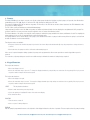
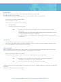
User’s Manual
Microdialysis syringe/ Nanoliter Infusion Pump
Eicom Model ESP-101
WEEE/RoHS Compliance Statement
EU Directives WEEE and RoHS
To Our Valued Customers:
We are committed to being a good corporate citizen. As part of that commitment,
we strive to maintain an environmentally conscious manufacturing operation. The
European Union (EU) has enacted two Directives, the first on product recycling
(Waste Electrical and Electronic Equipment, WEEE) and the second limiting the use
of certain substances (Restriction on the use of Hazardous Substances, RoHS).
Over time, these Directives will be implemented in the national laws of each EU
Member State.
Once the final national regulations have been put into place, recycling will be offered
for our products which are within the scope of the WEEE Directive. Products falling
under the scope of the WEEE Directive available for sale after August 13, 2005 will
be identified with a “wheelie bin” symbol.
Two Categories of products covered by the WEEE Directive are currently exempt
from the RoHS Directive – Category 8, medical devices (with the exception of
implanted or infected products) and Category 9, monitoring and control instruments.
Most of our products fall into either Category 8 or 9 and are currently exempt from
the RoHS Directive. We will continue to monitor the application of the RoHS
Directive to its products and will comply with any changes as they apply.
•
•
Do Not Dispose Product with Municipal Waste.
Special Collection/Disposal Required.......
Contents
1.
2.
3.
4.
5.
Specifications............................................................................................................................
General Safety Summary............................................................................................................
Features ...................................................................................................................................
Keypad Functions.......................................................................................................................
Operating Instructions
Power Switch ..........................................................................................................................
Main Menu..............................................................................................................................
Syringe Diameter Entry ............................................................................................................
Volume Entry............................................................................................................................
Flowrate Entry..........................................................................................................................
Starting the Pump....................................................................................................................
Power Failure Mode ................................................................................................................
Rate and Volume Changes While Running..................................................................................
Fast Forward............................................................................................................................
6. Loading the Syringe ...................................................................................................................
7. Manual Stall Settings and Microliter Syringes ..............................................................................
8. NV Ram Failure .........................................................................................................................
9. Fuses .......................................................................................................................................
10. Maintenance ...........................................................................................................................
11. Standard Table of Syringe Diameters .........................................................................................
12. Japanese Table of Syringe Diameters ........................................................................................
13. Standard Minimum and Maximum Flow Rates ...........................................................................
14. Limited Warranty.......................................................................................................................
2
3
4
4
5
5
5
5
6
6
6
7
7
7-8
9
9
9
9
10
11
12
13
US: eicom-usa.com, [email protected] | EU: eicomeurope.com, [email protected]
1. Specifications
100 Series, Including ESP-100, 101 and 120
Syringe Size
10 microliter to 60 milliliter
Electrical Rating
US model 115V~, 0.1A
CE model 230V~, 0.06A
Fuse
5x20 mm, 250V~ slow blow, 0.1A
Voltage Operating Range
US model 100-120V~, 50/60Hz
CE model 200-240V~,50/60Hz
Drive Mechanism
microprocessor controlled stepper gearmotor
(1⁄2 microcrostepping), driving a leadscrew through
a belt and pulley drive mechanism
Pusher Advance per Half Step
~0.529 micron or 2.083x10⁻⁵ inch (ESP-100)
~0.088 micron (ESP-101)
Linear Travel
ESP-100, ESP-120 minimum 0.00635 cm/hr; maximum 76.18 cm/hr
ESP-101
minimum 0.00106 cm/hr; maximum 12.2 cm/hr
Minimum Stepping Rate
one 1⁄2 step in thirty seconds – may vary depending
on syringe size
Maximum Stepping Rate
400 1⁄2 steps / second
Speed Range
12000:1
Flowrate Range
0.1μl/hr (10 μl syringe) to 506ml/hr
(60 ml syringe)
Linear Force
20 lb min. ( 9 Kgm)
Dimensions
9x6x5 inch (23x15.25x13 cm)
Weight
4.5 lb (2 Kgm)
Atmospheric Specifications
Temperature
4°C to 40°C (40°F to 104°F)
Humidity
20% to 80% RH, non-condensing
Mode of Operation
Continuous
Classification
Class I
Pollution Degree
2
Installation Category
II
Output
N/A
Physiological Effects
N/A
Cooling Conditions
No special considerations
Mechanical Stability
No special considerations
Protective Packaging
No special considerations
Earth Terminals
No External connections required
Removable Protective Means
N/A
Supplier Name
Eicom Europe
US: eicom-usa.com, [email protected] | EU: eicomeurope.com, [email protected]
2. General Safety Summary
Please read the following safety precautions to ensure proper use of your syringe pump. To avoid potential hazards and product damage, use this
product only as instructed in this manual. If the equipment is used in a manner not specified by the manufacturer, the protection provided by the
equipment may be impaired.
To Prevent Hazard or Injury:
•Use Proper Power Supply
The pump is supplied with an approved power supply and line cord.
•Use Proper Line Cord
Use only the line cord shipped with the product and make sure line cord is certified for country of use.
•Ground the Product
This product is grounded through the grounding conductor of the power cord. To avoid electric shock, use only approved line cord with the
product and insure it is connected to earth ground.
•Make Proper Connections
Make sure all connections are made properly and securely.
•Orient Equipment Properly
Do not position the equipment such that it is difficult to reach the disconnecting device.
•Observe all Terminal Ratings
Review the operating manual to learn the ratings on all connections.
•Avoid Exposed Circuitry
Do not touch any electronic circuitry inside of the product.
•Do Not Operate with Suspected Failures
If damage is suspected on or to the product do not operate the product. Contact qualified service personnel to perform inspection.
•Avoid Pinch Hazard
A pinch hazard may exist between the Pusher Block and End Blocks. Avoid placing fingers between these points while the pump is running.
•Observe all Warning Labels on Product
Read all labels on product to ensure proper usage.
CAUTION
Refer to Manual
Protective Ground
Terminal
CAUTION
This pump is not registered with the FDA and is not for clinical
use on human or veterinary patients. It is intended for research
use only.
US: eicom-usa.com, [email protected] | EU: eicomeurope.com, [email protected]
3. Features
The Model ESP100 series are simple, accurate cost effective syringe pumps designed to hold glass or plastic syringes, of any make, from 10 microliter
to 60 milliliter for the ESP-100; 10 μl to 15 ml for the ESP-120; and 10 μl to 10 ml for the ESP-101.
The models ESP-100 and ESP-101 are infusion only pumps. The flow rates of the ESP-101 are six times slower than that of the ESP-100 and the units
of flow rate are suitably adjusted.
The ESP-120 is a push-pull simultaneous infusion/withdrawal pump.
Setup and pump operation for all of the 100 series pumps are similar and extremely simple. A menu, displayed on an alphanumeric LCD “prompts” the
operator to make the necessary selections using the keypad for choice of features and numerical entries.
The internal diameter of the syringe is used by the control program to calibrate the pump and deliver the volume and flowrate selected. For simplicity the
syringe diameter is also used to set automatically the volume and flowrate units.
The syringe diameter can be entered directly or the syringe can be identified from a table of syringes held in memory. When the syringe is selected from
the table the diameter is entered automatically.
Two dispense modes are available:
•Disspense volume mode in which the pump keeps track of the volume dispensed and automatically stops the pump when a set target volume is
reached.
•Run mode where the pump runs at the set flowrate until manually stopped.
In the event of a power interruption during operation, the pump can be programmed to either resume operation or remain stopped when power is
returned.
For convenience, all pump settings are stored in non-volatile memory to minimize the number of setting changes required.
4. Keypad Functions
This key has two functions:
•Moves the display to the left
•Causes the numerical entry to decrease. To change the displayed number by a single unit press and release the key quickly. If the key is pressed
longer the number changes with increasing speed.
This key has two functions:
•Moves the display to the right
•Causes the numerical entry to increase. To change the displayed number by a single unit press and release the key quickly. If the key is pressed
longer the number changes with increasing speed.
SELECT
This key has three functions:
•Return to main menu when pressed repeatedly
•Selects the pulsing or “highlighted” feature of the main menu display.
•Enter numerical values.
RUN/STOP
•Turns the motor on and off.
•Acts as a “pause” during a dispense.
DISPLAY
After the pump is programmed an arrow on the right side of the display indicates the direction of operation. This arrow pulses when the pump is running.
US: eicom-usa.com, [email protected] | EU: eicomeurope.com, [email protected]
5. Operating Instructions
POWER SWITCH
The power switch is located at the right, rear corner of the pump. When the power is turned on the LCD will display the Volume or Rate setting. Press
the select key to return to the main menu.
MAIN MENU
Pressing select repeatedly will always return the display to the main menu. The main menu consists of five variables, three of which are displayed at all
times. The center variable pulses to indicate that this option can be reviewed or changed. The menu acts as a continuous loop and the arrow keys, are
used to move around the loop. The variable to be changed can be selected with the select key.
Dia
Table
Rate
Vol
Pwr Up
direct entry, syr dia (mm)
syr dia. mfr, size
flowrate, μl or ml/h
dispense vol, μl or ml
run/stop
SYRINGE DIAMETER ENTRY
Syringe diameter must be entered for automatic internal calibration. Once entered the diameter is entered, it is retained in non-volatile memory and need
not be entered again unless the syringe being used is changed. When a syringe diameter is changed the Volume and Rate settings are set to zero.
There are two methods of diameter entry.
•Internal Library
Select TABLE from the main line menu. The table of syringes is organized by manufacturer, then by glass or plastic, and then by size. Use the arrow keys
to scroll through the table and the select key to enter the correct setting.
First, scroll through the manufacturers and select the manufacturer of thesyringe used. The menu will next display either syringe type or syringe size.
Again, use the arrow keys to move through the table until the correct size is displayed. Press the select key when the correct syringe size is displayed.
This automatically enters the internal syringe diameter.
See Table of Syringe Diameters on page 12 for the syringe library.
•Direct Entry
From the main menu select DIA. The display will read “xx.xx mm”. Use the arrow keys to display the measured internal diameter of the syringe in
millimeters and
enter with the select key.
Changing the diameter clears the Volume and Rate settings, and the display will now prompt for the new Volume setting.
VOLUME ENTRY
The volume setting mode is selected from the main menu or is displayed automatically after changing the diameter.
Display reads: xx.xx μl (Units displayed in μl or ml depend on syringe diameter entered)
•Use the arrow keys to enter the dispense volume required.
•When the correct dispense volume is displayed save this number with the select key.
NOTE:
If no target dispense volume is required, enter volume = 0.0
The pump will run at the set flowrate until stopped manually or a stall occurs.
After setting a volume the menu prompts for the flowrate setting.
•When the pump runs, the actual dispensed volume will be displayed and willincrement until the set volume is reached, at which time the pump
will stop automatically.
US: eicom-usa.com, [email protected] | EU: eicomeurope.com, [email protected]
FLOWRATE ENTRY
RATE can be selected from the main menu or will be displayed automatically after the volume setting.
The display reads: Rate: X.X μl/h or X.X ml/h
Rate units are μl/h or ml/h, microliter or milliliter/hour and are selected automatically according to the syringe diameter.
•Use the arrow keys to display the flowrate required.
•Enter the rate with the select key.
•If the rate entered is out of range, a message is displayed
“ Max Rate XX ml/h”
To continue, enter a lower rate or select a larger
NOTE:
•If a dispense volume was set then the display will now change to “Volume : 0.0” ,that is, in automatic
dispense mode.
When the pump runs, the actual dispensed volume will be displayed and will increment until the set volume
is reached at which time the pump will stop automatically.
•If no dispense volume is set, the LCD displays the set flowrate andn when running, the directional indicator
arrow will pulse.
START THE PUMP
•Press the run/stop key to start the pump. A second press will stop the pump.
•If the pump is stopped during a dispense, the volume accumulator is not cleared - the dispense is paused. Restarting the pump with a second
press of the run/stop key continues the dispense to the target volume.
POWER FAILURE MODE
If there is a temporary power interruption, when no dispense volume is selected, the Power Up run/stop option allows the pump to either resume the
dispense when the power returns, or remain stopped but display a message warning of the power failure.
•Move the main menu to the right and select PWR UP.
•The display will read Power Up Run (or STOP). Use the arrow keys to change display and select the required option
RUN:
•After power is returned, the pump resumes normal operation. The display flashes PowerFailed to
acknowledge a power interruption. Press Select to display the Rate.
STOP:
•Pump does not run when power returns. The LCD displays the rate setting.
If a dispense volume is entered the power interruption stops the pump, clears the volume accumulator and returns the volume to the setpoint. Only if the
power failure
setting is “run” will the power failure warning be displayed.
US: eicom-usa.com, [email protected] | EU: eicomeurope.com, [email protected]
CHANGE OR REVIEW VOLUME SETTING WHILE RUNNING
While the pump is running it is possible to look at the volume and flowrate settings without interrupting the operation of the pump. If required, the
volume and flowrate settings can be changed while the pump continues to run. When the changes are entered the pump immediately changes to the
new settings.
•While operating, press select to return to the main menu.
•Select Volume to display the set dispense volume. If no change is required press select.
•For a volume change use the arrow keys and enter with the select key.
•The display moves to RATE, permitting a change if required. Press select if no change is required, or use the arrow keys to change the setting.
The select key immediately changes to the new flowrate and the volume display continues to increment, uninterrupted to the newdispense
setting.
NOTE: If the VOLUME is changed to a setting smaller than the volume already accumulated then the pump stops when
the new, smaller dispense volume is selected.
CHANGE OR REVIEW RATE SETTING WHILE RUNNING
•Press select to change the volume accumulator display to the main menu.
•Select RATE.
•Make rate changes, if required, and press select.
The pump immediately changes to the new flow rate and displays the continuing volume accumulation uninterrupted by the change in flow rate.
FAST FORWARD
Press the run and the keys simultaneously to actuate the fast forward mode. The pump travels at its maximum rate while both keys are pressed
simultaneously.
6. Loading The Syringe
ESP-100 AND ESP-101
(3) Syringe Clamp Knob
Syringe Plunger
(1) Pusher Block
Syringe Holder
(2) Release Button
US: eicom-usa.com, [email protected] | EU: eicomeurope.com, [email protected]
•To facilitate loading, the pusher block (1) can be released from the leadscrew and manually moved along the guide rods to accommodate the
syringe.
•Press the bronze release button (2) on the side of the black pusher block (1) to release theblock from the leadscrew.
•Raise the spring loaded retaining clamp knob (3) and rotate away from the syringe barrel.
•Place the syringe barrel in the V of the syringe holder, making sure that the flange of the syringe barrel is pressed against the side of the syringe
holder.
•Rotate and release the syringe clamp to hold the syringe in place.
•Press in release button (2) and move the pusher block back along the guide rods to makecontact with the syringe plunger.
GLASS SYRINGES
With some glass syringes the corners of the flange of the syringe barrel are rounded and can cause a tendency for the syringe barrel to ride up out of
the syringe holder.
To give a more secure, flatter surface to clamp against, an O-ring or metal collar can be placed over the barrel and pressed against the flange.
ESP-120 PUSH-PULL PUMP
Travel Direction
Withdraw
Withdraw Bracket
Syringe Clamp
Release Button
Syringe Rest
•To facilitate loading , the pusher block can be released from the leadscrew by pressing the bronze release button (1) and can be manually moved
along the guide rods to accommodate the syringes.
•First place the withdraw syringe in the withdraw syringe holder, using the spring loadedretaining clamp to retain the syringe barrel in the V of the
syringe holder.
•Make sure the barrel flange is held firmly by the withdraw clamp and that the adjusting screws on the withdraw clamp are firmly tightened.
•While keeping the button (1) pressed firmly “in” slide the block along the guide rods so that the syringe plunger flange can be retained by the
clamp on the pusher block. Tighten the locking screws on the adjusted syringe clamp.
•Loosen the locking screw on the Adjustable syringe rest and position the rest so that the plunger of the loaded syringe is pressed firmly against
the pusher block and the syringe barrel flange is pressed up to the syringe rest.
•The barrel of the loaded, infusion syringe should be clamped in the V of the syringe holder with the spring loaded clamp.
•Tighten the screw on the syringe rest to lock the rest in place on the guide rod.
US: eicom-usa.com, [email protected] | EU: eicomeurope.com, [email protected]
7. Manual Stall Setting and Microliter Syringes
•A movable collar, located on the rear guide rod, can be set to restrict travel of the pusher block. The block moves until stalling against the collar.
Stalling does no permanent damage but may result in increased wear on the drive mechanism and should not be used routinelybut only as a “fail
safe” device.
•Microliter syringes with fine wire plungers can be damaged if the plunger is forced into theend of the syringe barrel; the collar can be adjusted to
prevent this occurrence.
8. NV Ram Failure
•If the settings in the non-volatile memory become corrupted the display will read “NV Ram Failure” and the pump will not operate.
•To recover from this condition, the pump must be powered down and then turned on again.
•The pump will be re-initialized to the default settings and can now be programmed as normal.
•A second method of clearing the “NV Ram Failure” is to press select and then enter a changed rate setting.
9. Fuses
The fuses are located in the power entry module on the rear panel.
Fuse Holder
•The linecord must be first removed to gain access to the fuse holder.
•Fuses 5x20mm, 250V~ slow blow, 0.1A
Voltage Selector (CE version only)
If it is necessary to change the input voltage selection, disconnect the line cord from the entry module on the rear panel. Use a flat bladed screwdriver to
open the Fuse Holder access door. Remove the Fuse Holder, flip over, and reinstall. Close the access door. The new input
voltage selection should be visible through the door window. Install a proper line cord certified for the country of use.
10. Maintenance
•Maintenance is required only for the moving mechanical parts, which should be kept clean and lubricated. Occasionally, a small amount of light
machine oil should be applied to the guide rods and a small amount of grease or oil to the leadscrew.
•Solvents of any type should never be used to clean the pump. A mild detergent solution may
•be used to clean the keypad.
US: eicom-usa.com, [email protected] | EU: eicomeurope.com, [email protected]
11. Standard Table of Syringe Diameters
(1) “Air-Tite “All Plastic
(4) Hamilton
1000-Series Gastight
(7) Scientific Glass Engineering
SGE
1 cc
4.70 mm
2.5
9.70
10 µl
0.46 mm
25 µl
0.73 mm
5.0
12.48
25
0.73
50
1.03
10
15.89
50
1.03
100
1.46
20
20.00
100
1.46
250
2.30
30
22.50
250
2.30
500
3.26
50
28.90
500
3.26
1 ml
4.61 mm
1 ml
4.61 mm
2.5
7.28
2.5
7.28
5
10.30
10
14.57
(2) Becton Dickinson
Interim, WW design, Plastipak
1 cc
4.70 mm
5
10.30
3
8.59
10
14.57
11.99
25
23.03
1 cc
4.674 mm
10
14.48
50
32.57
3
8.865
20
19.05
6
12.600
30
21.59
12
15.621
5
60
(3) Becton Dickson
Glass - all types
26.60
(5) Popper & Sons, Inc.
Perfektum glass
(8) Sherwood - Monojet Plastic
0.25
3.45 mm
20
20.142
0.5
3.45
35
23.571
60
26.568
1
4.50
0.5 cc
4.64 mm
2
8.92
1
4.64
3
8.99
2.5
8.66
5
11.70
5
11.86
10
14.70
10
14.34
20
19.58
20
19.13
30
22.70
30
22.70
60
28.60
(6) Ranfac
(9) Terumo
1 cc
4.73 mm
3
9.00
5
13.04
10
15.79
20
20.18
30
23.36
60
29.45
2 cc
9.12 mm
5
12.34
10
14.55
20
19.86
10 µl
0.46 mm
30
23.20
25
0.73
50
27.60
100
1.46
250
2.30
500
3.26
1000
4.61
(10) Unimetrics
Series 9000
US: eicom-usa.com, [email protected] | EU: eicomeurope.com, [email protected]
12. Japanese Table of Syringe Diameters (Available in Japanese Models)
(1) “Air-Tite “All Plastic
(5) JMC Air-Tite pls
(9) Top
1 cc
4.70 mm
1 ml
4.66 mm
1 ml
4.70 mm
2.5
9.70
2
6.90
2
6.40
5.0
12.48
2.5
9.10
3
9.30
10
15.89
5
12.62
6
13.10
20
20.00
10
14.34
12
15.40
30
22.50
20
19.68
25
21.00
50
28.90
(2) Becton Dickinson
Interim, WW design, Plastipak
30
22.44
30
23.00
50
28.80
1 cc
4.70 mm
3
8.59
1 ml Short
5
11.99
10
(6) Nipro
(10) Terumo
1 ml
4.73 mm
6.61 mm
3
9.00
1 mil Long
4.75
5
13.04
14.48
3
9.53
10
15.79
20
19.05
5
12.96
20
20.18
30
21.59
10
15.78
30
23.36
20
20.07
30
23.17
(3) Becton Dickson
Glass - all types
0.5 cc
4.64 mm
1
4.64
1 ml sm
4.80 mm
2.5
8.66
1 ml lg
6.70
5
11.86
2 mm sm
6.70
10
14.34
2 ml lg
9.20
20
19.13
3
10.30
30
22.70
5
12.20
10
15.00
20
19.00
30
22.50
50
25.50
(4) Hamilton
1000-Series Gastight
10 µl
0.46 mm
25
0.73
50
1.03
100
1.46
250
2.30
500
3.26
1 ml
4.61 mm
2.5
7.28
5
10.30
10
14.57
25
23.03
(7) Hoshi
60
(11) Terumo Japan
1 ml sm
4.73 mm
1 ml lg
6.50
3
8.95
5
13.00
10
15.80
20
20.15
30
23.10
(8) Natsume
0.25 ml
2.60 mm
0.50
3.20
1
4.30
2
6.30
3
7.30
5
9.50
29.45
US: eicom-usa.com, [email protected] | EU: eicomeurope.com, [email protected]
13. Standard Minimum and Maximum Flow Rates
ESP-100
ESP-101
Syringe Size
Minimum
Maximum
Syringe Size
Minimum
Maximum
10 µl
0.1 µl / h
126 µl / h
10 µl
0.001 µl/ m
0.382 µl / m
25 µl
0.1 µl / h
318 µl / h
25 µl
0.001 µl/ m
1.010 µl / m
50 µl
0.2 µl / h
625 µl / h
50 µl
0.001 µl/ m
1.762 µl / m
100 µl
1.0 µl / h
1274 µl / h
100 µl
0.001 µl/ m
3.542 µl / m
250 µl
2.0 µl / h
3164 µl / h
250 µl
0.01 µl/ m
8.78 µl / m
500 µl
3.0 µl / h
6359 µl / h
500 µl
0.01 µl/ m
17.65 µl / m
1 ml
0.01 ml / h
13.2 ml / h
1 ml
0.1 µl/ m
35.20 µl / m
2.5 ml
0.02 ml / h
31.7 ml / h
2.5 ml
0.1 µl/ m
88.00 µl / m
3 ml
0.02 ml / h
44.9 ml / h
3 ml
0.1 µl/ m
122.50 µl / m
5 ml
0.03 ml / h
87.0 ml/ h
5 ml
0.1 µl/ m
176.20 µl / m
10 ml
0.1 ml / h
125 ml / h
10 ml
0.001 ml / m
0.351 ml / m
20 ml
0.1 ml / h
219 ml / h
30 ml
0.1 ml / h
282 ml / h
Syringe Size
Minimum
Maximum
10 µl
0.1 µl / h
126 µl / h
25 µl
0.1 µl / h
318 µl / h
50 µl
0.2 µl / h
625 µl / h
100 µl
1.0 µl / h
1274 µl / h
250 µl
2.0 µl / h
3164 µl / h
500 µl
3.0 µl / h
6359 µl / h
1 ml
0.01 ml / h
13.20 ml / h
2.5 ml
0.02 ml / h
31.70 ml / h
3 ml
0.02 ml / h
44.90 ml / h
5 ml
0.03 ml / h
87.0 ml / h
10 ml
0.1 ml / h
125 ml / h
ESP-120
US: eicom-usa.com, [email protected] | EU: eicomeurope.com, [email protected]
14. Limited Warranty
•Eicom USA warrants to the first consumer purchaser, for a period of one year from the date of purchase that this unit, when shipped in its original
container, will be free from defective workmanship and materials and agree that it will, at its option, either repair or replace the defective unit.
•This warranty does not extend to misuse, neglect or abuse, normal wear and tear, accident, modification or unauthorised repair.
•Eicom USA will not be liable or in any way responsible for any incidental or consequential economic or property damage. Some States do not
allow the exclusion of incidental or consequential damages, so the above exclusion may not apply to you.
•There are no implied warranties of merchantability, or fitness for a particular use, or of any other nature. Some states do not allow this limitation
on implied warranty, so the above limitation may not apply to you.
•If a defect arises within the warranty period contact Eicom USA.
•The customer is responsible for shipping charges and must first obtain a Return Material Authorization number (RMA) before the unit will be
accepted. If a replacement unit is issued it is covered only for the remainder of the original warranty period dating from the purchase of the
original device.
•This warranty gives you specific legal rights. You may also have other rights which vary from state to state.
Note: This pump is not registered with the FDA and is not for clinical use on patients.
Eicom USA
7098 Miratech Drive, Suite 100
San Diego, CA 92121
United States
Tel (888) 680-7775 Fax (858) 560-8040
www.eicom-usa.com
Eicom Europe
Ground Floor, Hilton House
Ardee Rd, Rathimines
Dublin 6, Ireland
Tel +353 1 902 2700 Fax +353 1 443 0784
www.eicomeurope.com
US: eicom-usa.com, [email protected] | EU: eicomeurope.com, [email protected]