1
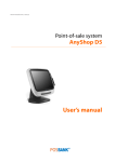
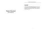
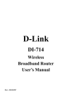
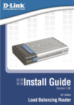
SB9100 User Manual Contents About this Manual Thank you for purchasing our SB9100 Series. This terminal offers highly enhanced features, with easy connection to various optional devices for optimum performance. This user manual describes how to setup and connect your terminal. Copyright © Copyright 2006 All rights reserved. This product and related documentation are protected by copyright and are distributed under licenses restricting their use, copying, and distribution. No part of this documentation may be reproduced in any form by any means without prior written authorization of the manufacturer and its licensors, if any. Safety Notices Before You Proceed • Read the safety notices and the User Manual carefully before turning the product on. • Keep the box and packaging in case the product needs to be shipped in the future. • Follow the product and warning label instructions. • Any changes or modifications that do not follow the instructions in this manual will void this productʹs warranty. Power Supply Safety Notes • To avoid electric shocks, disconnect the power cord from the electrical outlet before relocating the system. • Make sure the voltage of the power outlet conforms within voltage range of the terminal. Failure to comply may cause the electric shock or damage to the terminal. If you are not sure of the electricity voltage that you are using, contact your local electricity company. • To avoid fire or electric shocks, do not overload electric power outlets. • Protect the power cord from being walked on or pinched particularly at plug, convenience receptacles, and the point where they exit from the apparatus. iii Contents Operating IInstructions • Keep this manual for future reference. • Keep this equipment from moisture and dust. • Place the equipment on a stable surface before setting it up. • If there is any of the following situation arise, notify a qualified service technician immediately: ¾ The power cord or plug is damaged. ¾ Liquid has been spilt on to the equipment. ¾ The equipment has been dropped and damaged. ¾ The equipment does not function normally. • Do not block any ventilation openings to prevent the equipment from overheat. • Do not leave the equipment in a non air‐conditioned environment where the storage temperature may go above 70°C (158°F), as this can cause damage to the equipment. Maintenance • Gently wipe screen with a clean soft hair lens brush, or a lint‐free cloth. • Do not apply pressure to the screen while cleaning • Do not spray any liquid directly onto the screen or the casing of the SB9100 Terminal • Chemical cleaners have been reported to cause damage on the screen of the SB9100 Terminal. Warning and Attention • The technical descriptions and specifications of the equipment are subject to change without notice. • For safety reasons, wear gloves when assembling the product. Patent Patent pending. iv Contents Federal Communications (FCC Statement) This device complies with FCC Rules Part 15. Operation is subject to the following two conditions: • This device may not cause harmful interference. • This device must accept any interference received including interference that may cause undesirable operation. This equipment has been tested and found to comply within the limit of a Class A digital device, pursuant to Part 15 of the FCC Rules. These limits are designed to provide reasonable protection against harmful interference in a residential installation. This equipment generates, uses and can radiate radio frequency energy and, if not installed and used in accordance with the manufacturer’s instructions, may cause harmful interference to radio communications. However, there is no guarantee that interference will not occur in a particular installation. If this equipment does cause harmful interference to radio or television reception, which can be determined by switching the equipment on and off, the user is encouraged to try to correct the interference by one or more of the following measures: • Reorient or relocate the interference receiving antenna. • Increase the distance of separation between the equipment and interference receiver. • Connect the equipment to a power outlet on a circuit different from that to which the interference receiver is connected. • Consult the dealer or an experienced radio/TV technician for help. WARNING: The use of shielded cables for connection of the monitor to the graphics card is required to assure compliance with FCC regulations. Changes or modifications to this unit not expressly approved by the party responsible for compliance could void the user’s authority to operate this equipment. Note: Changes or modifications not expressly approved by the party responsible for compliance could void the user’s authority to operate the equipment. Contents Chapter 1 ..........................................................................................................1 Welcome ................................................................................................................. 1 Overview of SB9100......................................................................................... 1 Front View.................................................................................................. 2 Rear View ................................................................................................... 3 Connecting to a POS Terminal ................................................................ 4 Unpacking .................................................................................................. 4 Chapter 2 ..........................................................................................................4 Getting Started ...................................................................................................... 5 Pre‐installation Notice..................................................................................... 5 Default Settings.......................................................................................... 5 Limitations ................................................................................................. 6 Chapter 3 ..........................................................................................................7 System Upgrade .................................................................................................... 7 Removing the Cover........................................................................................ 7 Installing Add‐On Cards ................................................................................ 7 Installing a Hard Disk Drive .......................................................................... 8 Memory Configuration............................................................................. 8 Appendix .........................................................................................................9 Technical Information.......................................................................................... 9 Product Specifications..................................................................................... 9 Frequently Asked Questions (FAQ) ............................................................ 11 Troubleshooting............................................................................................. 12 vi Chapter 1 Chapter 1 Welcome Congratulations on your purchase of this POS PC. This product is specifically designed to offer you enhanced features, speed, and performance to promote your business higher flexibility and a superior customer experience. Overview of SB9100 This POS terminal comes equipped with the following features: Saving Cost of Ownership Modular design provides the owner with the following benefits: (a) cost effectiveness, (b) customization flexibility, and (c) easy maintenance. Compact Size/ Aesthetic Design This sturdy, power saving economic POS system features a sleek, compact design base that saves counter space and yields a variety of peripheral options, hence higher flexibility and adds appeal to the service environment. Dust/Water‐ proof IP32 SB9100 series features a highly durable, rigorously tested design that is reliable and dependable in rugged environments. POSReady 2009/ WinXP Pro Solution Solution is recommended to be bundled with embedded solution for high performance and other added values. Environment Protection Environmental friendly, RoHS compliant product. Higher Stability The SB9100 has a longer overall system MTBF to provide a higher stability during operation. 1 Chapte1 — Welcome Front View To open the front cover, press the cover release latch. Cover release latch DESCRIPTION 1 HDD bay 2 Power button 3 Key lock 4 LED status indicator 5 Two front access USB 2.0 ports 6 Headphone and microphone jacks 7 Compact flash card slot 2 Chapter 1 - Welcome Rear View DESCRIPTION FUNCTION 1 12V DC Output Connects to a LCD 2 24V DC Output Connects to a POS Printer 3 LPT 1 Connects to a POS Printer. 4 LAN Port Connects to the LAN. 5 Cash Drawer Port Connects to a cash drawer (12V/24V Solenoid Type of COM6) 6 Microphone Jack Connects to a microphone. 7 Audio Line In/Out Connectors Connects to audio source / external speakers. 8 Analog VGA Port Connects to a POS LCD monitor. 9 Two USB Ports Connect to USB 2.0 device. 10 COM Ports 1 – 4 Connect to POS peripherals. 11 PS/2 Keyboard Port Connects to a PS/2 keyboard. 12 PS/2 Mouse Port Connects to a PS/2 mouse. 13 AC Power Inlet Connects to an AC power cord. 14 Two Powered USB Ports 5V/24V Connect to a powered USB device. 3 Chapte1 — Welcome Connecting to a POS Terminal Your SB9100 POS PC collaborates with the Pyramid Touch Monitor to expand the capability and the flexibility for your business. 1. Connect one end of the VGA cable to the VGA port on the back of your SB9100 POS PC. 2. Connect the other end of the VGA cable to the VGA port on the back of the POS LCD Monitor. VGA Port on POS LCD Monitor VGA Cable VGA Port on POS PC Unpacking Before setting up your SB9100, check that the package contains the following items. If any of the items are missing or damaged, contact your vendor immediately. SB9100 POS PC AC POWER CORD ACCESSORY PACKAGE Contents of the Accessory Package: • Quick Installation Guide • Software Driver CD‐ROM • Front Cover Key Chapter 2 4 Chapter 2 Getting Started This chapter describes how to install the optional accessories on your SB9100 POS PC for optimum serviceability. Pre-installation Notice Before you start installing your SB9100, please read the following notices carefully. The SB9100 features two PCI slots. Do not plug in or unplug any interior devices, such as memory module or any function card, when the ATX PSU is powered on. The LAN chipset uses Intel Pro family network adapter. The Terminal has be built‐in the PXE Boot ROM function within the BIOS to execute Boot ROM already. For installation and compatibility, using the DDR RAM Module from the original manufacturer is recommended. The USB device connector is Hot Swap. Do not plug in or unplug any connectors other than USB devices when the power is on. The spill proof design of SB9100 conforms to IP‐32 standard. Do not insert or remove any devices or components from the SB9100 while the power is on. Default Settings Default settings for SB9100 POS PC serial ports COM1 COM2 COM3 COM4 IRQ 4 IRQ 3 IRQ 4 IRQ 3 5 Chapter 2 – Getting Started Limitations Output Voltage COM Port Average Max. Current 9 PIN of COM1 5V / 0.5A, 12V / 0.5A 5V / 0.7A, 12V / 0.6A 9th PIN of COM2 5V / 0.5A, 12V / 0.5A 5V / 0.7A, 12V / 0.6A 9th PIN of COM3 5V / 0.5A, 12V / 0.5A 5V / 0.7A, 12V / 0.6A 9th PIN of COM4 5V / 0.5A, 12V / 0.5A 5V / 0.7A, 12V / 0.6A th We strongly recommend that you use the following add‐on devices to expand the utilities of your SB9100 POS PC. Add‐on Card Type Model No. Brand Remarks LAN Realtek RTL8139C/ D 10/100 Base T SIS SIS900 10/100 Base T D‐Link DFE‐530TX 10/100 Base T 3 COM 3C905C 10/100 Base T Modem Card Motorola SM56 56K Conexant (Rockwell) MD‐56KUR4 56K Wireless LAN D‐Link DWL‐520+ IEEE 802.11b D‐Link DWL‐G520+ IEEE 802.11g CF Card InnoDisk 64MB ~8GB Industry Level Disk on Module InnoDisk 64MB ~4GB IDE ATA 44 pin 2nd VGA PCI Card ATI Radeon 7000 Card Bus 16/32 bit, 3.3V/5V PCMCIA PCI Slot Card 6 Chapter 3 Chapter 3 System Upgrade Your warranty remains in effect only if all internal settings are done by an authorized dealer or technician. This section is intended only for users who wish to perform adjustments by themselves and thereby void the warranty. Removing the Cover You will need the following tools to disassemble a SB9100 POS PC: • A screwdriver • Labeling material • A container to store the screws temporarily WARNING: Make sure that the power of your SB9100 POS PC is turned off before removing the chassis. Installing Add-On Cards You may need to install one or more add‐on card to expand the system capability in the future. The SB9100 POS PC includes two PCI slots for additional peripherals. WARNING: Due to the space saving design of the SB9100 POS PC, the dimensions of add-on cards are restricted to the size of 110mm (H) x 140mm(L). Make sure the add-on card conforms to the requirement before installation. After installing the add‐on card, perform card configuration. 7 Chapter 3 – System Upgrade Installing a Hard Disk Drive WARNING: If you purchase a SB9100 POS PC without a hard disk drive, contact your dealer for system upgrade. Memory Configuration You can increase the system memory for your SB9100 POS PC via onboard DDR Π SODIMM Socket. The SB9100 POS PC supports one bank of 256/512/1024 MB DIMM Modules. WARNING: Consult your dealer for memory upgrades. 8 Appendix Ap pendi x Technical Information Product Specifications ITEM SPECIFICATION Model Name SB9100 Processor Intel Celeron / Dual‐Core / Core 2 Duo Processor (LGA775) Memory 240‐pin DDR2 RAM * 2, up to 4GB (533/667) System Chipset Intel 945GC+ICH7 BIOS Award BIOS with enhanced ACPI 1.0 PnP/APM/DMI/ESCD/PCI bus 2.1/ On Now/ DRAM ECC AGP 3D Graphics Intel Graphics Media Accelerator 950, On Board Graphic Max. Share Memory Up To 224MB Parallel Port One LPT port (SPP/EPP/ECP), IRQ and address selectable by BIOS setup Serial Port Total 4 COM ports on board, IRQ selectable by BIOS setup Output on 9th pin by jumper selector. Each voltage output with poly switch protector. USB Port 2 X USB 2.0 Ports, 2 X Powered USB Port (5V/24V) IDE or SATA Port 1 X IDE Port 2 X SATA Port PCI Slots Support 2 X PCI Slots DC Output DC 12V Output X 1 DC 24V Output X 1 Thermal Solution One heat‐sink with Fan (Base on Fan Speed Control technology) for CPU Chip. One heat‐sink with Fan for N/B Chip. Compact Flash Card One bootable compact flash card socket (Type I/II) 9 Appendix — Technical Information ITEM SPECIFICATION Cash Drawer Port One cash drawer port with status sensor. (EPSON ESC Pin define) System Power ATX 250W Internal Power Supply. AC 100 to 240V Full Range. System Trigger Control System front side tact switch (ATX Trigger) below the LCD display with bottom. Ethernet Port Intel PRO 1000 Ethernet chip on board Intel Ethernet chips on board (10/100/1000 base‐ T) Audio AC97 CODEC on board Keyboard PS/2 Mouse PS/2 System Size 340mm (L) x 295mm (W) x 95mm (H) S/W Compatibility DOS / Windows 2000 / XP / XPE / WEPOS / Vista/ POSReady2009 / Windows 7 Operation Temperature 0°C to 40°C Storage Temperature ‐25°C to 70°C 10 Appendix — Technical Information Frequently Asked Questions (FAQ) Question 1: Why does the system appear unstable after updating BIOS? Answer: Load optimized defaults (or load SETUP Default) after flashing BIOS. If the system remains unstable, clear CMOS to solve the problem. Question 2: How do I clear CMOS? Answer: To clear CMOS, do the following: 1. Turn off power and switch off the power adapter. 2. Remove the jumper from clear CMOS 2‐3 PIN and insert the jumper to clear CMOS 1‐2 PIN. 3. Remove the jumper from clear CMOS 1‐2 PIN and re‐insert the jumper to clear CMOS 2‐3 PIN. 4. Switch on the power again. 5. Press Delete to enter CMOS setting and load optimized defaults. 6. Save changes and reboot the system. Question 3: How to use the Boot Menu? Answer: To use the Boot Menu, do the following: 1. Press F9 to enter the Boot Menu. 2. Select the Boot device from the Boot Menu. 11 Appendix — Technical Information Troubleshooting WARNING: If you encounter any trouble during boot up, please follow the troubleshooting procedures below to solve the problem. START Turn off the power and unplug the AC power cable. Remove all the add‐on cards, and cables from motherboard. Has the motherboard shorted out? YES Isolate the short pin. NO Failure has been excluded. Is the CPU cooling fan is working properly? Has the power NO been connected correctly? YES Failure has been excluded. Is the memory module correctly installed into the DIMM slot? NO YES Failure has been excluded. Plug in ATX power cable and turn on the POS PC. Next Page Plug in the power of the cooling fan. 12 Insert and push the memory module into the DIMM slot vertically. Appendix — Technical Information Is the LED on? Is the CPU fan running? NO YES Failure has been excluded. NO Is there any image on the display? The problem may be caused by power supply, CPU, memory, CPU, or memory socket. The VGA card, VGA card slot, or the monitor may be defective. YES Failure has been excluded. Turn off the system and reboot after the keyboard and the mouse are plugged in. NO Is the keyboard working? The keyboard or the keyboard connector may be defective. YES Press <Del> to enter BIOS setup mode. Select “Load Optimized Defaults”, save your selection, and exit setup. Failure has been excluded. Turn off the system and re‐connect the IDE cable. Reboot the system and see if it works. NO The IDE device / connector / cable may be defective. YES Reinstall Windows OS, the add‐on cards, and the cables. Try to reboot the system again. Failure has been excluded. Problem solved. Note: For questions about other error messages, please contact the technical support. 13