1
Technical Manual
TNC 122
April 97
This Technical Manual for the HEIDENHAIN TNC 122 straight cut control applies for the
NC software version 246 117 08 and is subject to change without notice.
Foreword
The HEIDENHAIN TNC 122 is a compact, three-axis straight cut control for machine tools with
central drive. It has been developed as the successor model for the TNC 121, to which it is
compatible for installation. The TNC 122 has an expanded range of functions.
This Technical Manual is intended for all machine tool builders and machine tool distributors, and for
retrofitting companies who wish to replaced an installed TNC 121 with a TNC 122. It provides the
information required for mounting, electrical connection and commissioning the control.
For information on the new and improved operating features, please refer to the User's Manual.
Contents
1
Specifications
4
2
Hardware
6
3
Software
6
4
EPROM Sockets
7
5
Power Supply
8
6
Grounding Diagram
9
7
Connections
10
8
8.1
9
9.1
Pin Layout
Data interface
Machine Integration
Encoders
11
15
16
16
9.2
Traverse ranges
17
9.3
Reference marks
18
9.4
Position feedback control of the NC axes
24
9.5
Monitoring functions
29
9.6
Display and operation
31
9.7
10
EMERGENCY STOP circuit
Exchanging the control
33
36
11
11.1
Machine Parameters
Entering and changing machine parameters
37
37
11.2
12
12.1
Machine parameter list
PLC Description
PLC-EPROM
38
45
45
12.2
PLC Commands
46
12.2.1
Load and store commands
46
12.2.2
Set commands
49
12.2.3
Logical connective operations
50
12.2.4
Arithmetic commands
52
12.2.5
Comparisons
54
12.2.6
Parenthetical expressions
55
12.2.7
Shift commands
56
12.2.8
Bit commands
57
12.2.9
Stack operations
57
12.2.10 Jump commands
59
12.3
Classes of markers and bytes
60
12.4
13
Marker list
Error Messages
61
65
14
Dimensions
66
15
Subject Index
69
4/97
TNC 122
Contents
3
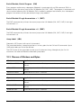
1 Specifications
Type of control
Straight cut control for 3 axes
and paraxial positioning
Program memory
Memory for up to 500 NC blocks,
20 NC programs
Design
Compact control for panel mounting
7-segment LED for actual position display
LED dot matrix 5 x 7 for preset display
Tool memory
One tool for length and radius compensation
Modes of operation
Manual operation
Positioning with manual data input
Program run single block
Program run automatic
Programming and editing
Program input
Manually through TNC keyboard
Through RS-232-C/ V.24
Display step
1 µm or 5 µm (0.000 05 in., 0.000 2 in.)
Programmable function
Languages
Nominal position in absolute or incremental dimensions
Subprograms, program section repeats
Tool radius compensation R+/RBolt-hole circle, hole circle segment, linear hole pattern
Feed rate / rapid traverse
M functions
Dutch, English, French, German, Spanish
Max. traverse
± 9999.999 mm
Max. traversing speed
30 000 mm/min
Position encoders
Incremental HEIDENHAIN position encoders, optionally
with distance-coded reference marks
16 µAPP /40 µAPP selectable
Grating Periods: 4, 10, 20, 40, 100, 200 µm
PLC cycle time
24 ms
Control inputs
3 position encoder inputs (sinusoidal inputs)
15 PLC inputs +1 PLC input for a control-is-ready
acknowledgment
Control outputs
One analog output (for central drive)
15 PLC outputs + 1 PLC input for control-is-ready signal
Data interface
RS-232-C/ V.24, up to 38 400 baud
4
TNC 122
1 Specifications
4/97
Power supply
Primary-clocked power supply 100 V to 240 V
Power consumption
19 W
Ambient requirements
Operation : 0° to +45° C
Storage : –30° to +70° C
Relative humidity, mean annual: < 75%, for max. 30 days
per annum, naturally distributed: < 95%
Weight
Approx. 3 kg
4/97
TNC 122
1 Specifications
5
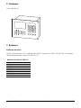
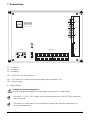
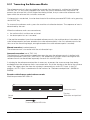
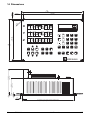
2 Hardware
Id. Nr. 284 083 xx
3 Software
Software versions
The NC software 246 117 07, together with the PLC software 277 938 13 of the TNC 122 replaces
the following software versions of the TNC 121:
Software Version of TNC 121
205 438
205 443
205 444
205 446
205 455
205 456 unipolar standard
205 457 bipolar standard
205 430
6
TNC 122
2 Hardware
4/97
4 EPROM Sockets
IC-P1 NC
IC-P2 PLC
The PLC EPROM is a 2 MB or 4 MB chip.
Danger of electrical shock!
Unplug the power cord before opening the housing.
Danger to internal components!
When handling components that can be damaged by electrostatic discharge (ESD),
observe the safety recommendations in DIN EN 100 015. Use only antistatic packaging
material. Be sure that the work station and the technician are properly grounded during
installation.
4/97
TNC 122
4 EPROM Sockets
7
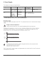
5 Power Supply
The voltage must comply with specifications:
Component
Power supply
Voltage range
NC
Max. power
consumption
—
Power consumption
Primary clocked 100 – 240 V
Approx. 19 W
power supply
(–15% to +10%)
48 – 62 Hz
Lower __
limit
PLC
24 V
Max. 10 mA per input
20.4 V....
(with basis
Max. 100 mA per output
Upper__limit
insulation
31 V .... 1)
according to
EN 50 178)
__
1) Voltage surges up to 36 V .... for t < 100 ms are permissible.
All small contactors and relays must have a quenching diode.
PLC power supply
The PLC (PLC inputs and outputs) of the TNC 122 is powered from the 24 V machine control voltage
supply.
Danger to internal components!
Connect inductive loads only with a quenching diode parallel to the inductance.
Superposed AC components as they arise from a three-phase bridge rectifier without smoothing
(see DIN 40110/1075, Section 1.2) must not exceed 5%. This results at the upper limit in the
absolute value 33.4 V and at the lower limit the absolute value of 18.5 V.
U
32.6 V
31 V
20.4 V
18.5 V
t
To increase the noise immunity, connect the ground terminal on the rear panel to the
central ground point of the machine.
(Minimum cross-section: 6 mm2)
The 0 V line of the PLC power supply must be grounded with an earth lead (∅ ≥ 6 mm2) to the main
frame ground of the machine.
8
TNC 122
5 Power Supply
4/97
2
3
TNC 122
TNC 122
X1
Line voltage
100 - 240V
Line frequency
50 - 60 Hz
X51 L1
SI
N
SI
X2
X3
stab. power
supply
1
PE
X21
Adapter
V.24
0V
X41/23
+24V-
+24V-
0V
15 outputs
0,1A
L
X41/33
Motor controller
with nominal value
0V difference input
Test point 2
(Fault voltg. with
grounded nominal
value input)
C
X41/48
X41/24
X41/47
C
X41
EMERGENCY STOP
0,1A
X41/10
16 inputs
V
C
SI
X41/9
C
0V
6 Grounding Diagram
3
X41/22
Optoc.
PLC supply voltage
with basic insulation
L
C
X41
2
2
6mm
6mm
2
6mm
B
1
0
2
6mm
2
6mm
Test point 1
(Fault voltg. 0V/
housing)
V
Pot. for
feed rate
C
B
If nominal value input is grounded,
a ground loop will result. Therefore
be sure that 0 V and ground wire
are short and configured for low noise.
6 Grounding Diagram
4/97
Machine-Encoders
1
9
7 Connections
X1
NC xxx xxx xx
PLC xxx xxx xx
X2
X3
X21
X51
X41(EXT)
1
L1 N
2
3
4
5
6
7
8
9
10 11 12 13 14 15 16 17 18 19 20 21 22 23 24
B
25 26 27 28 29 30 31 32 33 34 35 36 37 38 39 40 41 42 43 44 45 46 47 48
X1 = Encoder 1
X2 = Encoder 2
X3 = Encoder 3
X21 = RS-232-C/V.24 data interface
X41 = PLC inputs/PLC outputs/analog output/feed rate override/24 V PLC
X51 = Power supply
B = Signal ground
Danger to internal components!
Do not engage or disengage any connections while the unit is under power.
Interfaces X1, X2, X3, X21 comply with the recommendations in EN 50 178 for separation
from line power.
The outputs at connection X41 are metallically isolated from the device electronics by
means of optocouplers.
10
TNC 122
7 Connections
4/97
8 Pin Layout
X1, X2, X3
Pin number
Assignment
Encoder input
1
I1+
2
I1–
Flange socket with
5
I2+
9-pin female insert
6
I2–
7
I0+
8
I0–
3
+5V
4
0V
9
Internal shield
Housing
External shield
X21 Data interface
Pin number
Assignment
RS-232-C/V.24
1
Housing
2
RXD
D-sub connector with
3
TXD
25-pin female insert
4
CTS
5
RTS
6
DTR
7
GND signal ground
8 – 19
Do not use
20
DSR
21 – 25
Do not use
Pin number
Assignment
L1
Live (230 V, F2.5 A fuse)
X51 Power connector
Terminal board, 3-pole
N
Neutral
Protective ground
Power consumption: typically 10 W
4/97
TNC 122
8 Pin Layout
11
X41
TNC 122
Contact
Connection-assignment
PLC inputs
1
I8 High=M26/ Low=M27
PLC outputs
2
I9 High=M24/ Low=M25
Feed rate override
3
I10 High=M22/ Low=M23 or M09
PLC power supply
TNC 121
Contact
4
I11 High=M20/ Low=M21 or M05
5
I12 M08 coolant ON/ M09 OFF
Terminal board,
6
I13 M04 left spindle ON/ M05 OFF
48 contacts
7
I14 M03 right spindle ON/ M05 OFF
8
I15 acknowledgment M function
9
+24 V PLC
10
Control-is-ready output
11
O13 M04 left spindle ON/ M05 OFF or High=M18/
Low M19
12
O11 High=M20/ Low=M21 or M05
13
O9 High=M24/ Low=M25
14
O7 High=M28/ Low=M29
15
O5 Output for negative traverse direction (for onequadrant drives)
Erosion (205430) M02,M30 switches the output = 0
13
16
O4 Output for rapid traverse
(erosion 205430 M02,M30 Stop-erosion output=0)
11
17
O3 Output for Z axis enable
18
18
O2 Output for Y axis enable
20
19
O1 Output for X axis enable
22
20
O0 Output for Manual operating mode
16
21
not assigned
22
0 V Analog voltage
8
23
+/– 10 V Analog voltage (depending on MP 70)
9
24
Feed rate override (wiper)
4
25
I0 Input NC start
1
26
I1 Input NC stop
2
27
I2 Input rapid traverse key (Erosion 205430 erosion
ended, acknowledge with M36)
7
28
I3 Input for control-is-ready acknowledgment
29
I4 not assigned
30
I5 not assigned
31
I6 High=M23/ Low=M33
32
I7 High=M28/ Low=M29
33
0 V PLC
12
TNC 122
6
8 Pin Layout
4/97
X41
TNC 122
continued
Contact
34
Connection-assignment
TNC 121
Contact
O14 M04 right spindle ON/ M05 OFF or High=M16/
Low=M17
35
O12 M08 coolant ON/ M09 OFF
36
O10 High=M22/ Low=M23 or M09
37
O8 High= M26/ Low=M27
38
O6 High=M32/ Low= M33
39
24 V for neg. traverse direction output
12
40
24 V for rapid traverse output
10
41
24 V for Z axis enable output
17
42
24 V for Y axis enable output
19
43
24 V for X axis enable output
21
44
24 V for “manual“ / “not manual“ output
15
45
“Not manual” output (inverted O0)
14
46
not assigned
47
Feed rate override 0 V
3
48
Feed rate override 15 V
5
The assignments are in accordance with the PLC Standard Program Id. Nr. 277 938 13!
The 24 Vdc power supply is monitored for reverse polarity and overvoltage. Reverse
polarity blows a fuse (F 2.0 A). Overvoltage above 47 V destroys the damping diode and
blows the fuse. Maximum current load is 300 mA.
PLC outputs: Inductive loads are permitted only with anti-surge diode!
Change of the I/O assignment only if Program 205 430 is active:
With the M functions M02 an M30 the output is switched to zero. Through the M function M36 the
output O5 is switched to 1 and is used to start the erosion process. Through input I2 the function
M36 is acknowledged and indicates that erosion has ended. In this case the feed-rate potentiometer
is without function.
4/97
TNC 122
8 Pin Layout
13
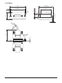
Installation of the Potentiometer:
6OLGHU
Internal-source voltage for pot
6OLGHU
External-source voltage for pot
14
TNC 122
8 Pin Layout
4/97
X21 Data Interface
The TNC 122 is equipped with an RS-232-C/V.24 data interface for operation in FE or EXT mode (see
the User's Manual). Programs and a list of the machine parameters can be output though this
interface. An RS-232-C adapter must be provided for a peripheral unit, such as a PC, FE 401, or
printer, to be connected to the control panel. The following drawing illustrates how to connect the
adapter block to X21.
HEIDENHAIN guarantees that, if properly connected, the RS-232-C/V.24 serial interface will reliably
transmit data between the TNC and a peripheral unit up to a distance of 20 meters.
HEIDENHAIN provides a standard cable 3 meters in length (Id.-Nr. 274 545 01) for connecting
peripheral units.
The data format in FE and EXT mode is fixed at 7 data bits, 2 stop bits and even parity. The FE mode
operates with ACK/NAK handshake, the EXT mode with DC1/DC3 handshake and RTS/CTS. The
data transfer rates are 9600 baud in FE mode and 2400 baud in EXT.
V.24-Adapter Block
max. 17 m
3m
Peripheral
unit
X21 RS-232-C/V.24
Id.-Nr. 239 758 01
Id.-Nr. 274 545 01
GND
TXD
RXD
RTS
CTS
DSR
GND
DTR
1
2
3
4
5
6
7
8
9
10
11
12
13
14
15
16
17
18
19
20
1
2
3
4
5
6
7
8
9
10
11
12
13
14
15
16
17
18
19
20
• WH/BN
•
•
WH/BN
GN •
YL
GY
PK
BL
RD
BN
•
•
1
2
3
4
5
6
7
8
9
10
11
12
13
14
15
16
17
18
19
20
1
2
3
4
5
6
7
8
9
10
11
12
13
14
15
16
17
18
19
20
•
•
•
1
2
3
4
5
6
7
8
9
10
11
12
13
14
15
16
17
18
19
20
Id.-Nr. 239 760..
1
2
3
4
5
6
7
8
9
10
11
12
13
14
15
16
17
18
19
20
• WH/BN
• YL
GN
PK
GY
BN
RD
BL
WH/BN
•
•
1
2
3
4
5
6
7
8
9
10
11
12
13
14
15
16
17
18
19
20
1
2
3
4
5
6
7
8
9
10
11
12
13
14
15
16
17
18
19
20
GND Chassis
RXD Receive data
TXD Transmit data
CTS Clear to send
RTS Request to send
DTR Data terminal ready
GND Signal ground
DSR Data set ready
The interface complies with the recommendations in EN 50 178 for separation from line
power.
4/97
TNC 122
8 Pin Layout
15
9 Machine Integration
9.1 Encoders
You can continue to use the same incremental position feedback encoders on the TNC 122, as you
used on the TNC 121.
Signal period
The signal period of the linear encoder is entered in machine parameter MP330.x (in µm). On linear
encoders with sinusoidal output signals, the signal period is the same as the grating period:
Signal period (~) = Grating period
The standard linear encoders from HEIDENHAIN have a grating period of 20 µm. Older encoders
have a grating period of 40 µm.
If linear position feedback is carried out with a rotary encoder on the ballscrew, then to calculate the
signal period you must consider not only the line count of the encoder (see the technical data for the
encoder) but also the pitch of the ballscrew:
Signal period (~) =
MP330
MP330.0
MP330.1
MP330.2
Screw pitch [mm] · 1000 [µm/mm]
Line count
Signal period
Input values: 4, 10, 20, 40, 100, 200 [µm]
Axis 1
Axis 2
Axis 3
Machine parameter MP7320 can set the encoder amplitude so that older encoder models (on
machines with TNC 121) can be adapted to the TNC 122.
MP7320
16
Switchover of encoder input amplitude
Input values: 0 to 7
Bit 0
Axis
X
Bit 1
Axis
Y
Bit 2
Axis
Z
TNC 122
+0 = 16 µA
+1 = 40 µA
+0 = 16 µA
+2 = 40 µA
+0 = 16 µA
+4 = 40 µA
9 Machine Integration
4/97
Traverse direction
Machine parameters MP210 and MP1040 define the axis traverse direction. The traverse directions
for the axes on numerically controlled machine tools are specified in DIN.
MP210 defines the counting direction of the encoder signals. The counting direction depends on the
mounting configuration of the encoders.
MP210
Counting direction of encoder signals
Input values: 0 to 7
Bit 0
Axis X
Bit 1
Axis Y
Bit 2
Axis Z
+0 = positive
+1 = negative
+0 = positive
+2 = negative
+0 = positive
+4 = negative
MP1040 defines the polarity of the nominal voltage for positive direction of traverse.
MP1040
Polarity of the nominal voltage with positive direction of traverse
Input values: 0 to 7 (must be "0" if MP70 is on "1" or "2")
Bit 0
Axis X
Bit 1
Axis Y
Bit 2
Axis Z
+0 = positive
+1 = negative
+0 = positive
+2 = negative
+0 = positive
+4 = negative
Assignment of encoder inputs
The individual axes can be assigned to the encoder inputs X1 to X3 with machine parameter MP110.
MP110
Assignment of axes to encoder inputs
Input values: 0 to 2
0 = encoder input X1
1 = encoder input X2
2 = encoder input X3
MP110.0
MP110.1
MP110.2
Axis 1
Axis 2
Axis 3
9.2 Traverse Ranges
The traverse ranges are set with machine parameters. The traverse ranges are defined by software
limit switches. The input values for the software limit switches are based on the scale datum.
If the machine moves to a software limit switch, the following error message appears:
LIMIT SWITCH <axis>...
and the corresponding marker is set (M2624 to M2629).
4/97
TNC 122
9 Machine Integration
17
MP 910
Positive traverse direction
Entry range: –9999.999 to +9999.999 [mm]
MP910.0
MP910.1
MP910.2
Software limit switch axis X+
Software limit switch axis Y+
Software limit switch axis Z+
MP 920
Negative traverse direction
Entry range: –9999.999 to +9999.999 [mm]
MP920.0
MP920.1
MP920.2
Software limit switch axis X–
Software limit switch axis Y–
Software limit switch axis Z–
M2624
M2625
M2626
M2627
M2628
M2629
Limit switch axis X+
Limit switch axis X–
Limit switch axis Y+
Limit switch axis Y–
Limit switch axis Z+
Limit switch axis Z–
Set
NC
NC
NC
NC
NC
NC
Reset
NC
NC
NC
NC
NC
NC
9.3 Reference Marks
For workpiece machining, the datum setting procedure assigns a unique position value (coordinate)
to each axis position. Since the actual position values are generated incrementally by the encoder,
this relationship between axis positions and position values must be restored each time the power is
interrupted.
HEIDENHAIN linear encoders are provided with one or more reference marks. When a reference
mark is traversed, a signal is generated that identifies that position as a reference point. After a
power interruption, crossing over the reference marks will restore the relationship between axis
slide positions and position values that was last established through the datum setting procedure.
Crossing over the reference marks also restores all machine-based references.
Since it is inconvenient to move the axes over large traverses to restore the reference point,
HEIDENHAIN recommends position encoders with distance-coded reference marks. On these
encoders the absolute position value is available after crossing two reference marks.
18
TNC 122
9 Machine Integration
4/97
9.3.1 Traversing the Reference Marks
The reference marks of the axes should be traversed after the control is switched on. Machines
with the TNC 121 are usually equipped with scales that have a reference mark at each end. To
prevent the software limit switch ranges from being shifted, always traverse the reference mark
upon which the software limit switches are based.
If referencing is not desired, it can be deactivated with machine parameter MP1340.x or by pressing
the NO ENT key.
To traverse the reference marks, press the machine axis direction buttons. The sequence of axes is
determined by the user.
When the reference marks are crossed over,
• the software limit switches are activated
• the datum point last set is restored
If the position encoders have distance-coded reference marks, the machine datum is based on the
scale reference point (on linear encoders the scale reference point is the first reference mark after
the start of the measuring length; on angle encoders the scale reference point is marked).
Manual execution (standard process)
The reference mark is traversed with the axis-direction keys.
Automatic execution (not in TNC 122)
The direction of traverse and the speed when crossing over the reference marks is defined with
machine parameters (MP1320.x, MP1330.x). The sequence of functions when crossing over the
reference marks can be defined separately for each axis with MP1350.x.
A trip dog for the reference end position is necessary to prevent the traverse range from being
exceeded when the reference marks are crossed over. Install the trip dog at the end of the traverse
range. The trigger signal line from the trip dog is connected to a vacant PLC input. In the PLC
program, this PLC input is combined with the markers for “Reference end position” (M2556 to
M2558)
Encoders with distance-coded reference marks
Machine parameter MP1350.x=0
Reference marks
Trip dog
"Reference end position"
Closed
Open
Traverse direction MP1320.x
4/97
TNC 122
9 Machine Integration
19
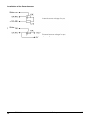
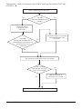
Sequence for “Automatic reference mark traverse” (pressing the machine START key).
MP1350.x = 0
Press the external START key
Trig dog
"Reference end position"
closed?
No
Yes
Machine moves
in direction from
MP1320.x
Trip dog
"Reference end position" is
closed before two successive
reference marks are
traversed
Machine moves in inverted
traverse direction from
MP1320.x
Yes
No
Two successive reference marks traversed
Is the machine
outside the software
limit switch range?
No
Yes
Machine moves to
software limit switch
Machine stops
20
TNC 122
9 Machine Integration
4/97
Encoders with one reference mark
Machine parameter MP1350.x = 1
Reference marks
Trip dog
"Reference end position"
Closed
Open
Traverse direction MP1320.x
4/97
TNC 122
9 Machine Integration
21
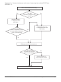
Sequence for “Automatic reference mark traverse” (pressing the machine START key).
MP1350.x = 1
Press the machine START key
No
Trip dog
"Reference end position"
closed?
Yes
Machine moves
in direction from
MP1320.x
Trip dog
"Reference end position"
is closed before reference
mark is passed over
Machine moves in
inverted direction from
MP1320.x
Yes
No
Reference mark is passed over
Is the machine
outside the software
limit switch range?
No
Yes
Machine moves to
software limit switch
Machine stops
22
TNC 122
9 Machine Integration
4/97
MP1320
MP1330
Traverse direction for crossing over the reference marks with EXT start
Input values: 0 to 7
Bit 0
Axis X
Bit 1
Axis Y
Bit 2
Axis Z
Feed rate for crossing over the reference marks
Entry range: 80 to 30 000[mm/min]
MP1330.0
MP1330.1
MP1330.2
MP1340
Axis X
Axis Y
Axis Z
Sequence when crossing over the reference marks
Input values: 0 = no reference mark evaluation
1 = 1st axis
2 = 2nd axis
3 = 3rd axis
MP1340.0
MP1340.1
MP1340.2
MP1350
+0 = positive
+1 = negative
+0 = positive
+2 = negative
+0 = positive
+4 = negative
Axis X
Axis Y
Axis Z
Sequence for crossing over reference marks
Input values: 0 = encoder with distance-coded reference marks
1 = encoder with one reference mark
MP1350.0
MP1550.1
MP1350.2
Axis X
Axis Y
Axis Z
M2556
M2557
M2558
Reference end position for axis X
Reference end position for axis Y
Reference end position for axis Z
4/97
TNC 122
Set
PLC
PLC
PLC
Reset
PLC
PLC
PLC
9 Machine Integration
23
9.4 Position Feedback Control of the NC Axes
The TNC 122 operates according to the principle of closed-loop control with servo lag. Servo lag
means that there is always a difference (trailing error) between the nominal position commanded by
the NC and the actual position of the axes. Closed-loop control would not be possible without this
difference.
The kv factor (position loop gain) must be matched to the machine (see also “Characteristic kink”). If
a very high kv factor is chosen the servo lag will be very small, but this may cause oscillations in the
machine axis. If the kv factor is too small, the new position will be reached too slowly.
The maximum feed rate (not the rapid traverse) is defined in machine parameter MP1010.0–2. It
represents the feed rate at an analog voltage of 11 V at the servo input.
The acceleration can be entered in machine parameter MP1060.x. It determines the ramp gradient
of the rising edge (MP1060.0–2) and the approach to the position (MP1060.3–5).
To improve the positioning behavior, machine parameter MP1051.x can be used to define a bottom
voltage below which the control will not go.
When the axis is in position (the positioning window has been reached) the “axis in position” marker
is set. The PLC program must then disable the position controller for the axes to come to a stop.
The optimum kv factor must be determined empirically. The following diagram illustrates traversing
behavior at different kv factors:
U [V]
kv correct
kv too large
kv too small
MP1810
MP1060.0-2
MP1060.3-5
t [s]
The kv factor (MP1810) is generally determined by the maximum feed rate of the machine (MP1010)
and the servo lag according to the following formula:
m/min
kv = position loop gain [ mm ]
m
ve = maximum feed rate [min]
sa = servo lag [mm]
kv = Ve
sa
or
sa = Ve
kv
24
TNC 122
9 Machine Integration
4/97
Rapid traverse control
For operation at rapid traverse, both programmed and manually actuated, MP80 determines the
analog supply voltage for the motor controllers. The machine's circuit diagram will indicate whether
the controller input should be supplied by external analog voltage or the analog voltage of the
control, and whether amplified tachometer signals are used.
Programming of rapid traverse: Select the axis, enter the value, press and hold the machine rapid
traverse button, confirm by pressing the "ENT" key.
External analog voltage for rapid traverse at the controller input (MP80 =1):
If MP80 = 1, the controller will be switched to external analog voltage supply when the machine
axes are moving at rapid traverse. The control loop remains closed although the control is not
monitoring it. The control does not begin monitoring the loop until the axis comes within a certain
distance to the target position. This distance is defined in MP4210 and is transmitted to the PLC. To
resume feedback control, the PLC resets the "rapid traverse" output (X41, pin 16).
In order to ensure that servo lag monitoring does not respond during rapid traverse, the control
operates internally with a rapid traverse from MP1010.3-5 and a “servo lag” is internally adjusted
such that it remains within the permissible range of servo lag monitoring (floating nominal value).
The servo lag internal adjustment is defined with machine parameter MP1850 such that no
oscillations result. The rapid traverse in MP1010.3-5 must correspond with the actual rapid traverse.
The correct setting for the internal adjustment can be checked in a special display (activated with
MP7322) showing the actual feed rate, the analog voltage of the control and the internal nominal
servo lag as a percentage of the actual servo lag.
If the display sways between 80% and 120% this results in oscillations within the control. These
oscillations can be prevented by properly setting MP1850. The setting in MP1010.x is correct if the
display remains stable at approx. 100%. The behavior of the floating nominal value can also be
measured at the analog output with an oscilloscope.
Analog voltage of the control for rapid traverse at the servo input of (MP80 = 2):
If the feedback input is supplied from the control during rapid traverse and the tachometer voltage
must be switched, then enter the value 2 in MP80. In MP1010.3-5 enter the same rapid traverse
rate as the machine had with the TNC 121.
MP1010
Feed rate at 10 V analog voltage
Input: 80 to 30 000 [mm/min]
MP1010.0
MP1010.1
MP1010.2
Axis X
Axis Y
Axis Z
Rapid traverse for amplified tachometer signals or external rapid traverse voltage
Input range: 80 to 30 000 [mm/min]
MP1010.3
MP1010.4
MP1010.5
4/97
Axis X
Axis Y
Axis Z
TNC 122
9 Machine Integration
25
MP1050
Analog voltage for rapid traverse
Input range: 4.5 to 11.0 [V]
MP1050.0
MP1050.1
MP1050.2
Axis X
Axis Y
Axis Z
MP1051
Lower limit of analog voltage
Input range: 0 to 35 [transformer increment]
(1 transformer increment = 2.93 mV)
MP1051.0
MP1052.1
MP1053.2
Axis X
Axis Y
Axis Z
MP70
Bipolar or unipolar analog voltage
Input: 0 or 2
0 = bipolar
1 = unipolar, traversing the position outputs 0 volt
2 = unipolar, traversing the position inverts the voltage
MP80
Supply voltage for position controller during rapid traverse
Input range: 0 to 2
0 = Reserved
1 = Controller input supplied with external voltage (MP1850)
2 = Controller input supplied with analog voltage from the control
MP1060
Acceleration during position approach
Input range: 0.001 to 3.0 [m/s2]
MP1060.0
MP1060.1
MP1060.2
Axis X
Axis Y
Axis Z
Deceleration during position approach
Input range: 0.001 to 3.0 [m/s2]
MP1060.3
MP1060.4
MP1060.5
Axis X
Axis Y
Axis Z
MP1810
kv factor
MP1810.0
MP1810.1
MP1810.2
m/min
Input range: 0.10 to 10.00 [ mm ]
Axis 1
Axis 2
Axis 3
26
TNC 122
9 Machine Integration
4/97
MP1850
Proportion for internal adjustment of servo lag (if MP80 = 1)
Input range: 0 to 65535
Characteristic kink
To enable correct processing of the internal nominal value on machines that have a high rapid
traverse speed, the kv factor must be adjusted to this speed range.
In such cases a characteristic kink can be entered, providing the following advantages:
• a normal kv factor for the machining feed rate
• a separate kv factor for rapid traverse
The position of this characteristic kink is defined in machine parameter MP1830. In the upper range
the kv factor is multiplied by the factor in MP1820.
U [V]
9
MP1810 · MP1820
MP1830
MP1810 (= kv)
sa
The kink point must lie above the range of machining feed rates. Under these conditions the lag can
be calculated as follows:
·
sa = Ve
kv
[
]
MP1830 [%] + 100 [%] – MP1830 [%]
100 [%]
MP1820 · 100 [%]
MP1820
Multiplication factor for the kv factor
Input range: 0.001 to 9.000
MP1820.0
MP1820.1
MP1820.2
Axis X
Axis Y
Axis Z
MP1830
Characteristic kink
Input range: 0.000 to 100.000 [%]
MP1830.0
MP1830.1
MP1830.2
Axis X
Axis Y
Axis Z
4/97
TNC 122
9 Machine Integration
27
Offset compensation
An offset error can be compensated. An offset error exists if the axis drifts when the controller input
is supplied with 0V analog voltage. If the axis does drift, an offset voltage must be output to prevent
the drifting. To define the analog offset voltage, press MOD and enter the code number 75 368 to
call the “AV OFFSET” dialog prompt. The optimum input value (a multiple of 2.93 mV = 1
transformer step) must be determined empirically. Before this, the bottom voltage must be set to
zero with MP1051. For bipolar drives, enter the proper algebraic sign for the voltage.
Feed rate enable
It is only possible to move the axes if the feed rate enable is present in marker M2451 and
complementary marker M2467. If the feed rate enable is removed, the analog voltage output is 0 V
and the axes stop moving immediately.
M2451
M2467
Feed rate enable
Complementary feed rate enable
Set
PLC
PLC
Reset
PLC
PLC
Axes in position
When the axes have reached the defined positioning window (MP1030.x), the “Axis in position”
markers are set by the NC. This is also done when the control voltage is switched on.
The markers will only be reset by the NC if the axes leave the positioning window when being
traversed. This also applies when the reference marks are crossed over.
M2008
M2009
M2010
Axis X in position
Axis Y in position
Axis Z in position
Set
NC
NC
NC
Reset
NC
NC
NC
Open the control loop
In order to lock or disengage an axis, the control loop must be opened by the PLC. As soon as the
“Axis in position” markers (M2008 to M2010) are reset, the control loop must be closed again so
that the axis can be moved. Before the control loop is closed, an actual and nominal value transfer
must be performed.
M2544
M2545
M2546
Open control loop axis X
Open control loop axis Y
Open control loop axis Z
Set
PLC
PLC
PLC
Reset
PLC
PLC
PLC
Actual/nominal value transfer
If markers M2552 to M2554 are set, the momentary actual position value is taken as the nominal
position value.
M2552
M2553
M2554
Actual/nominal value transfer axis X
Actual/nominal value transfer axis Y
Actual/nominal value transfer axis Z
28
TNC 122
Set
PLC
PLC
PLC
Reset
PLC
PLC
PLC
9 Machine Integration
4/97
9.5 Monitoring Functions
The NC monitors the axis positions and the dynamic behavior of the machine. If the fixed values in
the machine parameters are exceeded, an error message is displayed and the machine is stopped.
Position, standstill and movement are monitored.
Position monitoring
Machine parameters MP1720.x determine the range for the continuous position monitoring of the
machine (servo lag monitoring). Monitoring goes into effect as soon as the axes are under control of
the position control loop. If the limits in MP1720 are exceeded, the following blinking error message
appears:
POS. ERROR A <axis>
The control must be switched off to correct this error. Realistic input values are approximately 1 to
1.4 times the servo lag at rapid traverse.
MP1720
Position monitoring
Input range: 0.001 to 200.000 [mm]
Movement monitoring
At short intervals (several control cycles) the path actually traversed is compared with the nominal
path as calculated by the NC. If the path traversed during this interval deviates from the calculated
path, the following blinking error message will appear:
POS. ERROR C <axis>
Movement monitoring is not active below the voltage entered in machine parameter MP1140.
If 12 [V] is entered in this machine parameter, no movement monitoring will be in effect.
It is not possible to safely operate the machine without movement monitoring.
MP1140
Movement monitoring
Input range: 0.03 to 12.00 [V]
Standstill monitoring
This monitoring goes into effect when the axes have reached the positioning window. The range
within which the axes may move is defined in MP1110. As soon as the position deviation is larger
than the value in MP1110, the following blinking error message is displayed:
POS.ERROR D <axis>
The message will also appear during approach to a target position if an overshoot is larger than the
value entered in MP1110, or if the axis moves in the opposite direction at the beginning of a
positioning move.
MP1110
Standstill monitoring
Entry range: 0.001 to 30.000 [mm]
Positioning window
The positioning window defines the range within which the control considers a position to have
been reached. When the position has been reached, the control starts the execution of the next
block. The size of the positioning window is defined in MP1030.x.
4/97
TNC 122
9 Machine Integration
29
When the axes reach the positioning window, markers M2008 to M2010 are set.
MP1030
MP1030.0
MP1030.1
MP1030.2
Positioning window
Entry range: 0.001 to 2.000 [mm]
Axis X
Axis Y
Axis Z
Encoder monitoring
Monitoring of the encoder signals must be activated with MP31.
If the signal amplitude is faulty the following error messages can appear:
ENCODER <axis> DEFECT
AMPL <axis> TOO SMALL
OVERLOAD <axis>
MP31
30
If the signal amplitude is no longer being evaluated
If the signal amplitude is too small
If the signal amplitude is too large
Monitoring of the amplitude of the encoder signals
Input values: 0 to 7
Bit 0
Axis X
Bit 1
Axis Y
Bit 2
Axis Z
TNC 122
+0 = no monitoring
+1 = monitoring active
+0 = no monitoring
+2 = monitoring active
+0 = no monitoring
+4 = monitoring active
9 Machine Integration
4/97
9.6 Display and Operation
The position display can be set with MP7322 to show:
• the actual position referenced to the currently set datum
• the actual position referenced to the scale reference point
• the current trailing error
• the actual feed rates and the nominal voltage and % value for servo lag
MP7322
Position display
Input values: 0 to 3
0=
1=
2=
3=
Actual position referenced to the currently set datum
Current servo lag
Position referenced to scale reference point
Actual feed rates, nominal voltage, % value for trailing error
The display step for the axis positions can be selected with MP7290.
MP7290
Display step
Input values: 0 or 1
0 = 1 µm
1 = 5 µm
Machine parameter MP7285 can be used to define whether the position of the tool tip or the face of
the spindle (zero tool) is displayed as the actual value.
MP7285
Take tool length into account in position display
Input values: 0 or 1
0 = position of tool tip is displayed
1 = position of zero tool is displayed
The TNC 122 can switched to different dialog languages with machine parameter MP7230.
MP7230
Dialog language
Input values: 0 to 7
0 = German
1 = English
2 = French
3 = Dutch
4 = Spanish
5 to 7 = reserved
4/97
TNC 122
9 Machine Integration
31
Machine parameters can select whether the RAM and the EPROM are to be tested when the
control is switched on. When commissioning it is recommended that the memory test be
deactivated. The message “Memory test” is displayed during the memory test.
MP7690
Memory test at switch-on
Input values: 0 to 3
0=
1=
2=
3=
EPROM and RAM test at switch-on
EPROM test at switch-on
RAM test at switch-on
No memory test at switch-on
The TNC 122 can also be used when no machine is connected to it. MP7210 sets the modes it can
then be used in.
MP7210
Programming station
Input values: 0 to 2
0 = Control
1 = Programming station, PLC active
2 = Programming station, PLC not active
32
TNC 122
9 Machine Integration
4/97
9.7 EMERGENCY STOP Circuit
The control has one PLC input (X41/28) and one PLC output (X41/10) with the designation “Control is
ready” for the EMERGENCY STOP routine.
If a malfunction is recognized in the control, the TNC switches the control-is-ready output off, a
blinking error message appears on the screen, the PLC program is halted and the outputs are reset.
This error message cannot be cleared. When the error has been corrected it is necessary to run
through the switch-on routine again.
If the control-is-ready input is switched off by an event outside the control, the following error
message will appear:
EMERGENCY STOP
The NC then sets markers M2190 and M2191. This error message cannot be cleared until the
control voltage is switched on again.
When an EMERGENCY STOP occurs all outputs are reset.
The control evaluates an external EMERGENCY STOP like an external and internal stop. If the
EMERGENCY STOP button is pressed while an axis is moving, the axis is brought to a stop. I
If the EMERGENCY STOP causes the servo amplifier to block, the output nominal values can
exceed the position monitoring defined by machine parameters. In such a case the following error
message will be displayed:
POS. ERROR <axis>
M2190
M2191
Non-blinking error message displayed
EMERGENCY STOP displayed
4/97
TNC 122
9 Machine Integration
Set
NC
NC
Reset
NC
NC
33
9.7.1 EMERGENCY STOP Connection Diagram
In case of a malfunction, the control-is-ready output should switch the 24 V supply voltage off.
Because this function is so critical, the TNC 122 checks this output each time the power supply is
switched on.
HEIDENHAIN recommends the following wiring:
TNC 122
Switch opens briefly when the control voltage
of each microprocessor is switched on
X41/10
X41/9
"Control is
ready"
24V not
interruptible
EMERGENCY
STOP
buttons
"Control ready"
feedback
k1
k1
Control
voltage
on
X41/28
K1
+
-
24 V
PLC
If the control is not to be part of the EMERGENCY STOP circuit, output X41/10 must be shortcircuited with input X41/28.
34
TNC 122
9 Machine Integration
4/97
9.7.2 EMERGENCY STOP Flowchart
The external electronics must fulfill the prescribed basic requirements. In particular, the
acknowledgment for “control is ready” must be received within 200 ms.
X41/10
X41/28
1
2
3
4 5
6
7
8
9
Display
1
Waiting for control voltage.
2
Recognition of the control voltage at X41/28 and reset controlis-ready output at X41/10.
3
Maximum time until control-is-ready signal at X41/28 must go
to 0 (t < 200 ms). If time limit is exceeded, error message:
4
Recognition of acknowledgment, output X41/10 set.
5
Waiting for control voltage.
6
Normal control operation. Output and control-is-ready
acknowledgment are set.
7
Control voltage switched off by external event.
8
When the control voltage is switched on again the error
message can be cleared; then return to normal operation.
9
If an error is detected, the control switches off the control-isready output (X41/10).
4/97
TNC 122
NO CONTROL VOLTG
EMERG STOP DEFEC
NO CONTROL VOLTG
9 Machine Integration
EMERGENCY STOP
Blinking error message
35
10 Exchanging the Control
The control should be exchanged only on machines that are recommended by HEIDENHAIN. If you
wish to retrofit other machines, contact your HEIDENHAIN service representative.
The PLC EPROM contains the appropriate machine parameters and the PLC program for the
following software types of the TNC 121. These are activated with a code number (see below).
Software of the
TNC 121
PLC software no.
TNC 122
NC software no.
TNC 122
Code no.
205 438
1
205 443
2
205 329
2
205 444
205 446
3
277 939 14
246 117 08
4
205 455
5
205 456
6
205 457
7
205 430
8
The TNC 122 with standard PLC program can also replace a TNC 121 with SE 121
(see machine parameters MP4xxx for more information on this.)
Proceed as follows to replace the TNC 121 by the TNC 122:
Before removing the TNC 121
•
Check the software number to see whether the PLC and NC software number of the TNC 122
can perform the functions of the TNC 121 (see the above table). If there is any doubt, contact
your HEIDENHAIN service representative.
•
Determine the following parameters and functions of the machine with the TNC 121 still
installed:
What is the maximum feed rate? What is the analog voltage at the maximum feed rate?
Is the analog voltage for the rapid traverse supplied by the control or by an external source
(shown on wiring diagram)?
Are the drives bipolar or unipolar?
Axis lock yes/no?
Reference mark traverse desired yes/no?
•
Determine the pin layout of the terminal board using the circuit diagram and mark the wires for
the connection to X41 of the TNC 122.
Removing the TNC 121
•
Disconnect the power supply, disconnect the cable from the terminal board, remove the
encoder connector.
•
Remove the mounting screws, remove the housing.
36
TNC 122
10 Exchanging the Control
4/97
Installing the TNC 122
•
•
Insert sponge rubber gasket, slide unit into position, tighten screws.
Insert encoder connectors, wire connector X41 according to the documented layout of the
TNC 121 (see connector layout X41).
Connect power supply.
Differences compared to TNC 121:
Connect signal ground to the central ground point of the machine.
Include control-is-ready output (X41/10) and control-is-ready input (X41/28) in the emergency
stop circuit (see Section 9.7).
Commissioning the TNC 122:
•
•
•
Switch on the control.
Activate the appropriate PLC program and machine parameters with the code number as
follows:
– Press the MOD key
– Enter code number 77 80 83
– Press the ENT key
– Press the MOD key
– Enter the appropriate code number from the above list
– Press the ENT key
Depending on the model of machine and its mechanical condition it may be necessary
to re-optimize the machine parameters that affect the control loop. especially
parameters MP1010, MP1030, MP1050, MP1051, MP1060, MP1810 and MP1850.
This requires checking the analog output and the tachometer voltage with an
oscilloscope.
If desired, set the software limit switch ranges to conform to maximum permissible traverse.
Note: The software limit switches are always referenced to a fixed reference mark!
Ensure that the same reference mark is always used for referencing.
Test all functions.
11 Machine Parameters
11.1 Entering and Changing Machine Parameters
A list of machine parameters is accessible through the MOD function Code number in the manual
operation mode. To call the complete list of machine parameters, enter the code number 95148. A
subset of MOD functions is more readily available through the MOD function User parameters. The
machine parameters included in the user parameters are indicated in the following list with *). It is
possible to change these parameters.
The values of the machine parameters can be changed as follows:
•
Select the list of machine parameters.
•
Use the arrow key to select the desired machine parameter.
•
Enter the new value.
•
Confirm your entry by pressing ENT.
To leave the list of machine parameters, press DEL.
4/97
TNC 122
11 Machine Parameters
37
11.2 Machine Parameter List
Machine
Parameter
Function and input
Input value
MP 31
Monitoring of encoder signal amplitude
Input values: 0 to 7
Bit 0 Axis X
+0
inactive
+1
active
Bit 1 Axis Y
+0
inactive
+2
active
Bit 2 Axis Z
+0
inactive
+4
active
MP 40
Displayed axes
Input values: 0 to 7
Bit 0 Axis X
+0
+1
Bit 1 Axis Y
+0
+2
Bit 2 Axis Z
+0
+4
not displayed
displayed
not displayed
displayed
not displayed
displayed
MP70
Analog output bipolar or unipolar
Input values: 0 or 2
0 = bipolar
1 = unipolar (ensure that MP1040 = 0!)
traversing the end position outputs 0 V
2 = unipolar, traversing the end position inverts
the nominal-value voltage
MP80
Analog voltage source for rapid traverse from
the control or from external source
Input values: 0 to 2
0 = reserved
1 = analog voltage from external source
2 = analog voltage from control
(Position control loop closed)
MP110.0-2
Assignment of encoder inputs to the machine
axes
Input values: 0 to 2
0 = encoder input X1
1 = encoder input X2
2 = encoder input X3
MP210
Counting direction of encoder signals
Input values: 0 to 7
Bit 0 Axis X
+0 = positive
+1 = negative
Bit 1 Axis Y
+0 = positive
+2 = negative
Bit 2 Axis Z
+0 = positive
+4 = negative
MP330.0-2
Grating period
Input values: 4, 10, 20, 40, 100, 200 [µm]
38
TNC 122
11 Machine Parameters
4/97
Machine
Parameter
Function and input
MP910.0-2
Software limit switch max. value
Input range:
–9 999.99 to +9 999.99 [mm]
MP920.0-2
Software limit switch min. value
Input range:
–9 999.99 to +9 999.99 [mm]
MP1010.0-5
Rapid traverse for normal and amplified
tachometer signals
Input range: 80 to 30 000 [mm/min]
MP1010.0-2 normal rapid traverse for X, Y, Z
MP1010.3-5 increased rapid trav. for X, Y, Z
MP1030.0-2
Positioning window
Input values: 0.005 to 2.000 [mm]
MP1040
Polarity of nominal value voltage for positive
traversing direction
Input values: 0 to 7
Bit 0 Axis X
+0 = positive
+1 = negative
Bit 1 Axis Y
+0 = positive
+2 = negative
Bit 2 Axis Z
+0 = positive
+4 = negative
If MP70 = 1, then MP1040 must
equal 0.
MP1050.0-2
Analog voltage for rapid traverse
Input values: 4.5 to 11 [V]
10 V
MP1051.0-2
Lower limit of analog voltage
Input values: 0 to 35 [ factor 2.93 mV]
Acceleration
Input values: 0.001 to 3.000 [m/s2]
1060.0 to 1060.2: accelerate
1060.3 to 1060.5: decelerate
Standstill monitoring
Input values: 0.001 to 30.000 [mm]
Motion monitoring
Input values: 0.03 to 10 [V]
Traverse direction when crossing over the
reference marks
Input values: 0 to 7
Bit 0 Axis X:
+ 0 = positive
+ 1 = negative
Bit 1 Axis Y:
+ 0 = positive
+ 2 = negative
Bit 2 Axis Z:
+ 0 = positive
+ 4 = negative
MP1060.0-5
MP1110
MP1140
MP1320
4/97
TNC 122
Input value
11 Machine Parameters
39
Machine
Parameter
Function and input
MP1330.0-2
Feed rate for crossing over the reference marks
Input values: 80 to 30 000 [mm/min]
MP1340.0-2
Sequence of axes for crossing over the
reference marks
Input values: 0 to 3
0 = no reference mark evaluation
1 = Axis X
2 = Axis Y
3 = Axis Z
MP1350.0-2
Type of referencing
Input values: 0 or 1
0 = encoder with distance-coded reference
marks
1 = encoder with one reference mark
MP1720
Position monitoring with servo lag
(EMERGENCY OFF)
Input values: 0 to 200 [mm]
MP1810.0-2
kv factor for operation with servo lag
Input values: 0.1 to 10 [1/min]
MP1820
Multiplication factor for the kv factor
Input values: 0.001 to 9
MP1830
Characteristic kink for the kv factor
Input values: 0 to 100 [%]
MP1850
Factor for internal servo-lag adjustment with
external rapid traverse voltage
Input values: 0 to 65535
40
TNC 122
Input value
Only if MP80 = 1
11 Machine Parameters
4/97
Machine
Parameter
Function and input
Input value
MP4110
Time for timers T0 to T15
Input values: 0 to 65 535 [24 ms]
MP4110.0
Waiting time controller enable X
MP4110.1
Waiting time unclamp X start
MP4110.2
Waiting time clamp X stop
MP4110.3
Waiting time controller enable Y
MP4110.4
Waiting time unclamp Y start
MP4110.5
Waiting time clamp Y stop
MP4110.6
Waiting time controller enable Z
MP4110.7
Waiting time unclamp Z start
MP4110.8
Waiting time clamp Z stop
MP4110.9
SE pulse formation / duration
MP4110.10
Waiting time O5 traverse
direction, delay erosion start M36
MP4110.11
Delay time for rapid traverse
output O4 (night erosion switchoff)
MP4110.12
MP4110.13
MP4110.14
MP4110.15
MP4120.0
to
MP4120.7
Preset value for counters C0 to C7
Input values: 0 to 65 535
MP4210
Setting a number in the PLC word range
D768 to D804
Input values: –9 999.999 to +9 999.999 [mm]
MP4210.0
X switch-off point for rapid trav.
MP4210.1
Y switch-off point for rapid trav.
MP4210.2
Z switch-off point for rapid trav.
MP4210.3
Position control loop to XYZ potentiometer=0,
NC stop, lag<0.5
Only with MP 4310.4 and .5 =1
MP4210.4
Number of D/A converter steps per PLC cycle
with control by PLC
Input approx. 0.4
MP4210.5
Multiplication factor for the feed rate
potentiometer
Potentiometer value * MP4210.5= NC % block
Input approx. 0.1 to 1.2
External pot. 100%: factor 0.66
External pot. 150%: factor 1.0
Selection of code no. for software level for
position control loop via PLC
Input 1 to 8 (for software level of
TNC 121, see Chapter 10)
MP4210.6
MP4210.7
MP4210.8
MP4210.9
4/97
TNC 122
11 Machine Parameters
41
Machine
Parameter
Function and input
MP4220
Setting a number in the PLC word range
W960 to W968
Input values: 0 to 65535
Input value
MP4220.0
1 = bipolar without SE functions
2 = unipolar without SE functions
5 = bipolar with SE functions
6 = unipolar with SE functions
12 = erosion with SE functions
MP4220.1
0=
+1 =
+2 =
+4 =
+8 =
+16 =
+32 =
+64 =
+128 =
+256 =
MP4220.2
Static M output
M03/M05 impulse or
M16/M17 impulse
M04/M05 impulse or
M18/M19 impulse
M08/M09 impulse
M20/M21 impulse
M22/M23 impulse
M24/M25 impulse
M26/M27 impulse
M28/M29 impulse
M32/M33 impulse
0=
M acknowledgment to
I15
+1 =
M03 automatic
+2 =
M04 automatic
+4 =
M8/M9 automatic
+8 =
M16/M17 automatic
+16 =
M18/M19 automatic
+32 =
M20/M21 automatic
+64 =
M22/M23 automatic
+128 = M24/M25 automatic
+256 = M26/M27 automatic
+512 = M28/M29 automatic
+1024 = M32/M33 automatic
+2048 = M00/M02/M05/M30
automatic
MP4220.3
If potentiometer closed, NC stop feed rate
potentiometer minimum
Minimum potentiometer feed
rate 0%
MP4220.4
If potentiometer closed, NC stop feed rate
potentiometer maximum
Active minimum potentiometer
feed rate 0%
A change to the machine parameters MP4220.x only becomes active after a power
interruption.
42
TNC 122
11 Machine Parameters
4/97
Machine
Parameter
Function and input
Input value
MP4310
Setting a number in the PLC marker range
M2192 to M2211
Input values: 0 or 1
MP4310.0
X trav. direction 0=neg., 1=pos.
MP4310.1
Y trav. direction 0=neg., 1=pos.
MP4310.2
Z trav. direction 0=neg., 1=pos.
MP4310.3
Actual and nominal value transfer
in automated operational mode
0 = no, 1=yes
MP4310.4
1 = open position control loop
when override closed or NC stop
MP4310.5
Only effective if MP 4310.4 is active
1 = no controller enable when
override closed or NC stop
MP4310.6
1 = rapid traverse output O4 set
in automated operating mode
MP4310.7
1 = M05 output via O11
(M20/M21) and reset via M03,
M04, M13, M14;
M09 output via O10 (M22/M23)
and reset via M08, M13, M14
MP4310.8
0 = EMERGENCY STOP cancels
the SE outputs
1 = EMERGENCY STOP does not
cancel the SE outputs
MP4310.9
Position control loop
0 = NC control
1 = PLC control
MP4310.10
0 = M functions active in MDI
1 = M functions not active in MDI
MP4310.11
1= switch off PLC position
control loop monitoring
MP4310.12
1= rapid traverse information (MP
block) is not switched when the
advance switch point is reached
MP4310.13
MP4310.14
MP4310.15
MP4310.16
MP4310.17
MP4310.18
MP4310.19
A change to the machine parameters MP4310.x only becomes active after a power
interruption.
4/97
TNC 122
11 Machine Parameters
43
Machine
Parameter
Function and input
Input value
MP7210 *)
Programming station or machine control
Input values: 0 to 2
0 = control
1 = programming station, PLC active
2 = programming station, PLC not active
MP7230 *)
Dialog language
Input: 0 to 7
0 = German
1 = English
2 = French
3 = Dutch
4 = Spanish
5 = reserved
6 = reserved
7 = reserved
MP7285 *)
Tool length is included in the position display
value for the tool axis
Input values: 0 or 1
0 = tool length is included
1 = tool length is not included
MP7290 *)
Display step 1 µm or 5 µm
Input values: 0 or 1
0 = 1µm
1 = 5 µm
MP7320
Encoder signal amplitude
Input values: 0 to 7
0 = 16µA encoders
+1 = 40µA encoders on X-axis
+2 = 40µA encoders on Y-axis
+4 = 40µA encoders on Z-axis
MP7322 *)
Position display mode
Input values: 0 to 3
0 = display actual position
1 = display servo lag
2 = display reference position
3 = display actual feed rate and nominal value
voltage
MP7680 *)
Memory function for axis direction buttons
Input values: 0 or 1
0 = not stored
1 = stored
MP7690
Memory test during switch-on or after reset
Input values: 0 to 3
+0 = memory test during switch-on
+1 = no RAM test during switch-on
+2 = no EPROM test during switch-on
44
TNC 122
11 Machine Parameters
4/97
12 PLC Description
The TNC 122 features an integrated PLC for 15 inputs and 15 outputs. PLC programs for specific
machine models (see Chapter 10) have been prepared and stored by HEIDENHAIN in the EPROM.
If in rare cases the PLC program must be altered or rewritten, we recommend using the PLC.EXE
programming software, version 2.2 from HEIDENHAIN. This program can also generate the binary
code for the PLC EPROM (see the User's Manual for PLC.EXE).
The PLC program assigns fixed functions to the inputs and outputs at the X41 terminal block (see
Chapter 8 "Pin Layout."
In the TNC 122 the PLC program is run directly from the EPROM; there is no RAM memory for this
task.
For servicing purposes the logical status of the markers, inputs, outputs, timers and counters can be
transmitted through the RS-232-C/V.24 port to a computer. Transmission is activated by entering the
code number 807 667 in the TNC 122.
Under menu item "File/TNC 12x Monitor" the program PLC.EXE provides a function (PLCMONI.EXE)
for immediately displaying the logical status of operands, provided that the code number was
entered.
• Use the rightward cursor key on the TNC to scroll through the markers.
• Use the "R+/-" key on the TNC to scroll back through the markers.
• Press the NO ENT key to leave the display.
12.1 PLC EPROM
The PLC EPROM is a 2-MB or 4 MB chip with 16-bit data organization. It is programmed in Motorola
format, which means that the most significant byte of a word is located at the first (lowest) address.
Addresses:
$00000
...
$00400
$00402
$00403
$00405
$00406
...
$0041C
$0041E
$00420
$007E0
$0000
...
PLC Program start address
Chip identifier (1 word)
PLC program length
$0000
10th MP list
...
2nd MP list
1st MP list
$0000
PLC Program in binary format
and
up to 10 machine parameter tables
$1C000
20 PLC error messages in 7 languages
20 dialogs in 7 languages (30 characters each)
PLC software number
Checksum
One's complement checksum
$1FF00
$1FFFC
$1FFFE
4/97
TNC 122
12 PLC Description
45
The error messages and dialogs are filed in the individual languages in the sequence and syntax
('...',0). Each dialog can have up to 16 characters (see also the User's Manual for PLC.EXE).
German
English
French
'..............................',0
'..............................',0
'..............................',0
12.2 PLC Commands
12.2.1 Load and store commands
LOAD (L)
Logic execution with the LOAD command
Operands: M, I, O, T, C
The addressed operand is copied into the Logic Accumulator. An L command is always used at the
start of a logic chain to enable subsequent gating commands.
Word execution with the LOAD command
Operands: B, W, D, K
The addressed operand (B, W, D) or a Constant (K) is copied or loaded into the Word Accumulator.
The sign is added if necessary. In contrast to logic execution, an L command must always be used
at the start of a word gating chain. It is not possible to use a gating command.
LOAD NOT (LN)
Logic execution with the LOAD NOT command
Operands: M, I, O, T, C
The complement of the addressed operand is loaded into the Logic Accumulator. A load command is
always used at the start of a logic chain to enable subsequent gating commands.
Word execution with the LOAD NOT command
Operands: B, W, D, K
The content of the addressed operands (B, W, D) or a Constant (K) is loaded into the Word
Accumulator as a complement. The sign is added if necessary. In contrast to logic execution, a load
command must always be used at the start of a word gating chain. It is not possible to use a gating
command.
LOAD TWO'S COMPLEMENT (L–)
Operands: B, W, D, K
The contents of the addressed operand (B, W, D) or a Constant (K) is loaded into the Word
Accumulator as a two's complement. The sign is added if necessary. The two's complement allows
negative numbers to be stored, i.e. if a number is loaded with L–, it appears in the Accumulator with
the opposite sign. This command can only be used with Word execution.
46
TNC 122
12 PLC Description
4/97
LOAD BYTE (LB)
Operands: M, I, O, T, C
The LB command copies 8 Markers, Inputs, Outputs, Timers or Counters with ascending numbering
into the Word Accumulator. Each operand occupies 1 bit in the Accumulator. The designated
operand address occupies the LSB in the Accumulator, the designated address + 1 the LSB + 1 and
so on. In this way, the last affected operand occupies the MSB. The sign is added if necessary.
LOAD WORD (LW)
Operands: M, I, O, T, C
The LW command copies 16 Markers, Inputs, Outputs, Timers or Counters with ascending
numbering into the Word Accumulator. Each operand occupies 1 bit in the Accumulator. The
designated operand address occupies the LSB in the Accumulator, the designated address + 1 the
LSB + 1 and so on. In this way, the last affected operand occupies the MSB The sign is added if
necessary.
LOAD DOUBLEWORD (LD)
Operands: M, I, O, T, C
The LD command copies 32 Markers, Inputs, Outputs, Timers or Counters with ascending
numbering into the Word Accumulator. Each operand occupies 1 bit in the Accumulator. The
designated operand address occupies the LSB in the Accumulator, the designated address + 1 the
LSB + 1 and so on. In this way, the last affected operand occupies the MSB.
ASSIGN (=)
Logic execution with the ASSIGN command
Operands: M, I, O, T, C
In conjunction with a Logic Operand (M, I, O, T, C), ASSIGN copies the contents of the Logic
Accumulator into the addressed operand. ASSIGN is only used at the end of a logic chain to ensure
that a gating result is available. The command can be used several times in succession.
Word execution with the ASSIGN command
Operands: B, W, D
ASSIGN in conjunction with a Word Operand (B, W, D) copies the contents of the Word
Accumulator into the addressed operand. In contrast to bit execution, ASSIGN can also be used
within a word logic chain. The command can be used several times in succession.
4/97
TNC 122
12 PLC Description
47
ASSIGN BYTE (B=)
Operands: M, I, O, T, C
ASSIGN BYTE copies 8 bits from the Word Accumulator to Markers, Inputs, Outputs, Timers or
Counters with ascending numbering. Each bit corresponds to one operand. The LSB in the
Accumulator is copied to the designated operand address, the LSB + 1 to the designated address
+ 1 and so on. The last affected operand is occupied by the MSB.
ASSIGN WORD (W=)
Operands: M, I, O, T, C
ASSIGN WORD copies 16 bits from the Word Accumulator to Markers, Inputs, Outputs, Timers or
Counters with ascending numbering. Each bit corresponds to one operand. The LSB in the
Accumulator is copied to the designated operand address, the LSB + 1 to the designated address
+ 1 and so on. The last affected operand is occupied by the MSB.
ASSIGN DOUBLEWORD (D=)
Operands: M, I, O, T, C
ASSIGN DOUBLEWORD copies 32 bits from the Word Accumulator to Markers, Inputs, Outputs,
Timers or Counters with ascending numbering. Each bit corresponds to one operand. The LSB in
the Accumulator is copied to the designated operand address, the LSB + 1 to the designated
address + 1 and so on. The last affected operand is occupied by the MSB.
ASSIGN NOT (=N)
Logic execution
Operands: M, I, O, T, C
In conjunction with a logic operand (M, I, O, T, C), ASSIGN NOT copies the complement of the
contents of the Logic Accumulator into the addressed operand. See ASSIGN (=) for the sequence of
operations.
Word execution
Operands: B, W, D
In conjunction with a word operand (B, W, D), ASSIGN NOT copies the complement of the contents
of the Word Accumulator into the addressed operand.
ASSIGN TWO'S COMPLEMENT (=-)
Operands: B, W, D
ASSIGN TWO'S COMPLEMENT copies the TWO'S COMPLEMENT of the contents of the Word
Accumulator into the addressed operand.
48
TNC 122
12 PLC Description
4/97
12.2.2 Set commands
SET (S)
Operands: M, I, O, T, C
The function of this command depends on the contents of the Logic Accumulator. If the Logic
Accumulator = 1, the addressed operand is set to 1; otherwise the operand remains unchanged. An
S command is used at the end of a logic chain so that the gating result influences the operand. The
command can be used several times in succession.
RESET (R)
Operands: M, I, O, T, C
The function of this command depends on the contents of the Logic Accumulator. If the Logic
Accumulator = 1, the addressed operand is set to 0; otherwise the operand remains unchanged. An
R command is used at the end of a logic chain so that the gating result influences the operand. The
command can be used several times in succession.
SET NOT (SN)
Operands: M, I, O, T, C
The function of this command depends on the contents of the Logic Accumulator. If the Logic
Accumulator = 0, then the addressed operand is set to 1; otherwise the operand remains
unchanged. An SN command is used at the end of a logic chain so that the gating result influences
the operand. The command can be used several times in succession.
RESET NOT (RN)
Operands: M, I, O, T, C
The function of this command depends on the contents of the Logic Accumulator. If the Logic
Accumulator = 0, then the addressed operand is set to 0; otherwise the operand remains
unchanged. An RN command is used at the end of a logic chain so that the gating result influences
the operand. The command can be used several times in succession
4/97
TNC 122
12 PLC Description
49
12.2.3 Logical Connective Operations
AND (A)
Logic execution with the AND command
Operands: M, I, O, T, C
This command functions in different ways depending on its position in the program:
a) At the start of a logic chain the command functions as an L command. That is, the logic state of
the operand is loaded into the Logic Accumulator.
b) Within a logic chain the contents of the Logic Accumulator and the logic state of the operand
(M, I, O, T, C) are gated with AND. The result of the operation is stored in the Logic Accumulator.
Word execution with the AND Command
Operands: B, W, D, K
The contents of the Word Accumulator and the contents of the operand (B, W, D, K) are gated with
AND. In accordance with the different sizes of operand (B = 8 bits; W = 16 bits; D = K = 32 bits),
8, 16 or 32 bits will be influenced in the Accumulator.
Thus: Bit 0 of the Accumulator is gated with bit 0 of the operand
Bit 1 of the Accumulator is gated with bit 1 of the operand, and so on.
AND NOT (AN)
Logic execution with the AND NOT command
Operands: M, I, O, T, C
This command functions in different ways depending on its position in the program:
a) At the start of a logic chain the command functions as an LN command. That is, the complement
of the operand is loaded into the Logic Accumulator.
b) Within a logic chain, the contents of the Logic Accumulator and the logic state of the operand
(M, I, O, T, C) are gated with AND NOT. The result of the operation is stored in the Logic
Accumulator.
Word execution with the AND NOT command
Operands: B, W, D, K
The contents of the Word Accumulator and the contents of the operand (B, W, D, K) are gated with
AND NOT. In accordance with the different sizes of operand (B = 8 bits; W = 16 bits;
D = K = 32 bits), 8, 16 or 32 bits will be influenced in the Accumulator.
Thus: Bit 0 of the Accumulator is gated with bit 0 of the operand
Bit 1 of the Accumulator is gated with bit 1 of the operand, and so on.
The result of the operation is stored in the Word Accumulator.
50
TNC 122
12 PLC Description
4/97
OR (O)
Logic execution with the OR command
Operands: M, I, O, T, C
This command functions in different ways depending on its position in the program:
a) At the start of a logic chain the command functions as an L command. That is. the logic state of
the operand is loaded into the Logic Accumulator.
b) Within a logic chain, the contents of the Logic Accumulator and the logic state of the operand
(M, I, O, T, C) are gated with OR. The result of the operation is stored in the Logic Accumulator.
Word execution with the OR command
Operands: B, W, D, K
The contents of the Word Accumulator and the contents of the operand (B, W, D, K) are gated with
OR. In accordance with the different sizes of operand (B = 8 bits; W = 16 bits; D = K = 32 bits),
8, 16 or 32 bits will be influenced in the Accumulator.
Thus: Bit 0 of the Accumulator is gated with bit 0 of the operand
Bit 1 of the Accumulator is gated with bit 1 of the operand, and so on.
The result of the operation is stored in the Word Accumulator.
OR NOT (ON)
Logic execution with the OR NOT command
Operands: M, I, O, T, C
This command functions in different ways depending on its position in the program:
a) At the start of a logic chain this command functions as an LN command. That is, the
complement of the operand is loaded into the Logic Accumulator.
b) Within a logic chain, the contents of the Logic Accumulator and the logic state of the operand
(M, I, O, T, C) are gated with OR NOT. The result of the operation is stored in the Logic
Accumulator.
Word execution with the OR NOT command
Operands: B, W, D, K
The contents of the Word Accumulator and the contents of the operand (B, W, D, K) are gated with
OR NOT. In accordance with the different sizes of operand (B = 8 bits; W = 16 bits; D = K = 32 bits),
8, 16 or 32 bits will be influenced in the Accumulator.
Thus: Bit 0 of the Accumulator is gated with bit 0 of the operand
Bit 1 of the Accumulator is gated with bit 1 of the operand, and so on.
The result of the operation is stored in the Word Accumulator.
EXCLUSIVE OR (XO)
Logic execution with the EXCLUSIVE OR command
Operands: M, I, O, T, C
This command functions in different ways depending on its position in the program:
a) At the start of a logic chain the command functions as an L command. That is, the logic state of
the operand is loaded into the Logic Accumulator.
b) Within a logic chain the contents of the Logic Accumulator and the logic state of the operand (M,
I, O, T, C) are gated with EXCLUSIVE OR. The result of the operation is stored in the Logic
Accumulator.
4/97
TNC 122
12 PLC Description
51
Word execution with the EXCLUSIVE OR command
Operands: B, W, D, K
The contents of the Word Accumulator and the contents of the operand (B, W, D, K) are gated with
EXCLUSIVE OR. In accordance with the different sizes of operand (B = 8 bits; W = 16 bits;
D = K = 32 bits), 8, 16 or 32 bits will be influenced in the Accumulator.
Thus: Bit 0 of the Accumulator is gated with bit 0 of the operand
Bit 1 of the Accumulator is gated with bit 1 of the operand, and so on.
The result of the operation is stored in the Word Accumulator.
EXCLUSIVE OR NOT (XON)
Logic execution with the EXCLUSIVE OR NOT command
Operands: M, I, O, T, C
This command functions in different ways depending on its position in the program:
a) At the start of a logic chain this command functions as a LN command. That is, the complement
of the operand is loaded into the Logic Accumulator.
b) Within a logic chain the contents of the Logic Accumulator and the logic state of the operand (M,
I, O, T, C) are gated with EXCLUSIVE OR NOT. The result of the operation is stored in the Logic
Accumulator.
Word execution with the EXCLUSIVE OR NOT command
Operands: B, W, D, K
The contents of the Word Accumulator and the contents of the operand (B, W, D, K) are gated with
EXCLUSIVE OR NOT. In accordance with the different sizes of operand (B = 8 bits; W = 16 bits; D =
K = 32 bits), 8, 16 or 32 bits will be influenced in the Accumulator.
Thus: Bit 0 of the Accumulator is gated with bit 0 of the operand
Bit 1 of the Accumulator is gated with bit 1 of the operand, and so on.
The result of the operation is stored in the Word Accumulator.
12.2.4 Arithmetic Commands
ADDITION (+)
Operands: B, W, D, K
With arithmetic functions the operand is first expanded to the size of the Accumulator (32 bits). Then
the contents of the operand are added to the Word Accumulator. The result of the operation is
stored in the Word Accumulator and can be processed further.
SUBTRACTION (–)
Operands: B, W, D, K
With arithmetic functions the operand is first expanded to the size of the Accumulator (32 bits). Then
the contents of the operand are subtracted from the contents of the Word Accumulator. The result
of the operation is stored in the Word Accumulator and can be processed further.
52
TNC 122
12 PLC Description
4/97
MULTIPLICATION (x)
Operands: B, W, D, K
With arithmetic functions the operand is first expanded to the size of the Accumulator (32 bits). Then
the contents of the operand are multiplied with the contents of the Word Accumulator. The result of
the operation is stored in the Word Accumulator and can be processed further. If the result of
multiplication causes an overflow, Marker M3168 is set; otherwise it is reset.
DIVISION (/)
Operands: B, W, D, K
With arithmetic functions the operand is first expanded to the size of the Accumulator (32 bits). Then
the contents of the Word Accumulator are divided by the contents of the operand. The result of the
operation is stored in the Word Accumulator and can be processed further. If division by 0 is
attempted, the Marker M3169 is set; otherwise it is reset.
REMAINDER (MOD) D
Operands: B, W, D, K
With arithmetic functions the operand is firstly expanded to the size of the Accumulator (32 bits).
Then the REMAINDER is determined by dividing the contents of the Word Accumulator by the
contents of the operand. The REMAINDER is stored in the Word Accumulator and can be processed
further. If the MOD command is not correctly executed then the Marker M3170 is set; otherwise it
is reset.
INCREMENT (INC, INCW)
INCREMENT operand (INC)
Operands: B, W, D
The content of the addressed operand is increased by one.
INCREMENT Word Accumulator (INCW)
The content of the Word Accumulator is increased by one.
DECREMENT (DEC, DECW)
DECREMENT operand (DEC)
Operands: B, W, D
The content of the addressed operand is decreased by one.
DECREMENT Word Accumulator (DECW)
The content of the Word Accumulator is decreased by one.
4/97
TNC 122
12 PLC Description
53
12.2.5 Comparisons
EQUAL TO (==)
Operands: B, W, D, K
With this command a direct transfer from Word to Logic processing occurs. The content of the
Word Accumulator is compared with the content of the addressed operand. If the Word
Accumulator is equal to the operand, the condition is true and the Logic Accumulator is set to 1. If
they are not equal, the Logic Accumulator is set to 0. The comparison takes place over the number
of bits corresponding to the operand, i.e. B = 8 bits, W = 16 bits and D = K = 32 bits.
LESS THAN (<)
Operands: B, W, D, K
With this command, a direct transfer from Word to Logic processing occurs. The content of the
Word Accumulator is compared with the content of the addressed operand. If the Word
Accumulator is smaller than the operand, the condition is true and the Logic Accumulator is set to 1.
If the Word Accumulator is greater than or equal to the operand, the Logic Accumulator is set to 0.
The comparison takes place over the number of bits in the operand, i.e. B = 8 bits, W = 16 bits and
D = K = 32 bits.
GREATER THAN (>)
Operands: B, W, D, K
With this command, a direct transfer from Word to Logic processing occurs. . The content of the
Word Accumulator is compared with the content of the addressed operand. . If the Word
Accumulator is greater than the operand, the condition is true and the Logic Accumulator is set to 1.
If the Word Accumulator is less than or equal to the operand, the Logic Accumulator is set to 0. The
comparison takes place over the number of bits in the operand, i.e. B = 8 bits, W = 16 bits and D =
K = 32 bits.
LESS THAN OR EQUAL TO (<=)
Operands: B, W, D, K
With this command, a direct transfer from Word to Logic processing occurs. The content of the
Word Accumulator is compared with the content of the addressed operand. If the Word
Accumulator is less than or equal to the operand, the condition is true and the Logic Accumulator is
set to 1. If the Word Accumulator is greater than the operand, the Logic Accumulator is set to 0. The
comparison takes place over the number of bits in the operand i.e. B = 8 bits, W = 16 bits and D = K
= 32 bits.
GREATER THAN OR EQUAL TO (>=)
Operands: B, W, D, K
With this command, a direct transfer from Word to Logic execution occurs. The content of the Word
Accumulator is compared with the content of the addressed operand. If the Word Accumulator is
greater than or equal to the operand, the condition is true and the Logic Accumulator is set to 1. If
the Word Accumulator is smaller than the operand, the Logic Accumulator is set to 0. The
comparison takes place over the number of bits corresponding to the operand, i.e. B = 8 bits,
W = 16 bits and D = K = 32 bits.
54
TNC 122
12 PLC Description
4/97
UNEQUAL (<>)
Operands: B, W, D, K
With this command, a direct transfer from Word to Logic execution occurs. The content of the Word
Accumulator is compared with the content of the addressed operand. If the Word Accumulator and
the operand are not equal, the condition is true and the Logic Accumulator is set to 1. If the Word
Accumulator is equal to the operand, the Logic Accumulator is set to 0. The comparison takes place
over the number of bits corresponding to the operand, i.e. B = 8 bits, W = 16 bits and D = K = 32
bits.
12.2.6 Parenthetical Expressions
Parentheses with logical commands
The execution sequence in an instruction list can be altered by using parentheses. The openparentheses command loads the contents of the Accumulator onto the Program Stack. If the Logic
Accumulator is addressed in the last command before an open-parentheses instruction, the content
of the Logic Accumulator is loaded into the Program Stack. By addressing the Word Accumulator,
the content of the Word Accumulator will be distributed.
The close-parentheses instruction initiates the gating of the buffered value from the Program Stack
with the Logic Accumulator and/or the Word Accumulator, depending on which Accumulator was
addressed before the open-parentheses instruction. The result is then available in the corresponding
Accumulator. The maximum nesting level is 16 parentheses.
AND [ ]
AND NOT [ ]
OR [ ]
OR NOT [ ]
EXCLUSIVE OR [ ]
EXCLUSIVE OR NOT [ ]
(A[ ])
(AN[ ])
(O[ ])
(ON[ ])
(XO[ ])
(XON[ ])
Parentheses with arithmetic commands
With arithmetic commands, only word execution is possible. The execution sequence in an
instruction list may be altered by using parentheses. The open-parentheses command loads the
content of the Word Accumulator onto the Program Stack. The Accumulator is then available for the
calculation of intermediate results. The close-parentheses instruction initiates the gating of the
buffered value from the Program Stack with the content of the Word Accumulator. The result is
again loaded into the Accumulator. The maximum nesting level is 16 parentheses.
ADDITION [ ]
SUBTRACTION [ ]
MULTIPLICATION [ ]
DIVISION [ ]
REMAINDER [ ]
4/97
TNC 122
(+[ ])
(–[ ])
(x[ ])
(/[ ])
(MOD[ ])
12 PLC Description
55
Parentheses with comparison commands
The execution sequence in an instruction list can be altered by using parentheses. The openparentheses command loads the contents of the Word Accumulator onto the Program Stack. The
Accumulator is now available for the calculation of intermediate results.
The "close-parentheses" instruction initiates the gating of the buffered value from the Program Stack
with the content of the complete Word Accumulator. The result is again loaded into the
Accumulator. The maximum nesting depth is 16 parentheses.
A direct transition from Word to Logic execution takes place with comparison commands. If the
comparison condition is true, the Logic Accumulator is set to 1. If the condition is not true, the Logic
Accumulator is set to 0.
EQUAL TO [ ]
LESS THAN [ ]
GREATER THAN [ ]
LESS THAN OR EQUAL TO [ ]
GREATER THAN OR EQUAL TO [ ]
UNEQUAL [ ]
(==[ ])
(<[ ])
(>[ ])
(<=[ ])
(>=[ ])
(<>[ ])
12.2.7 Shift Commands
SHIFT LEFT (<<)
Operands: B, W, D, K
Since the sign bit (MSB) is included with this command, it is grouped in with arithmetic commands.
For this reason and out of time considerations, this command should not be used for the isolation of
bits. A SHIFT LEFT instruction causes the contents of the Word Accumulator to be multiplied by
two. For this purpose the bits in the Accumulator are simply shifted one place to the left. The result
must be within the range of –2 147 483 648 to +2 147 483 647, otherwise the Accumulator will
contain an undefined value. The number of shift operations is determined by the operand; the right
side of the Accumulator is filled with zeros.
SHIFT RIGHT (>>)
Operands: B, W, D, K
Since the sign bit (MSB) is included with this command, it is grouped in with arithmetic commands.
For this reason and out of time considerations, this command should not be used for the isolation
of bits. A SHIFT RIGHT instruction causes the contents of the Word Accumulator to be divided by
two. For this purpose the bits in the Accumulator are simply shifted one place to the right. The
number of shift operations is determined by the operand. The set bits, which are shifted beyond
the Accumulator to the right, are lost; the Accumulator is filled from the left-hand side including
the sign.
56
TNC 122
12 PLC Description
4/97
12.2.8 Bit Commands
BIT SET (BS)
Operands: B, W, D, K
With this command, each bit in the Accumulator can be accessed. The BS command sets the
addressed bit to 1. The selection (addressing) of the corresponding bit is derived from the content of
the specified Operand or a Constant. In the bit-numbering, bit 0 corresponds to the LSB and bit 31
corresponds to the MSB. For operand contents larger than 32, the operand value Modulo 32 is
used — that is, the integer remainder from the division (operand value)/32.
BIT CLEAR (BC)
Operands: B, W, D, K
With this command, each bit in the Accumulator can be accessed. The BC command sets the
addressed bit to 0. The selection (addressing) of the corresponding bit is derived from the content of
the specified Operand or a Constant. In the bit-numbering, bit 0 corresponds to the LSB and bit 31
corresponds to the MSB. For operand contents larger than 32, the operand value Modulo 32 is
used — that is, the integer remainder from the division (operand value)/32.
BIT TEST (BT)
Operands: B, W, D, K
With this command, the status of each bit in the Accumulator can be interrogated. With BT
commands, a direct transition from Word to Logic execution takes place. The BIT TEST tests the
status of a bit from the Word Accumulator and then acts correspondingly on the Logic Accumulator.
If the tested bit is 1, the Logic Accumulator is set to 1; if it is 0, the Logic Accumulator is set to 0.
The program continues in logic execution. The selection (addressing) of the corresponding bit is
derived from the content of the specified Operand or a Constant. In the bit numbering, bit 0
corresponds to the LSB and bit 31 corresponds to the MSB. For operand contents larger than 32,
the operand value Modulo 32 is used — that is, the integer remainder from the division (operand
value)/32.
12.2.9 Stack Operations
Load Data onto the Data Stack (PS)
Logic Execution with the PS Command
Operands: M, I, O, T, C
With the PS command, data is buffered by loading the addressed operand onto the Data Stack.
Since the Data Stack is 16-bit, a minimum width of one Word must be used when writing to it.
During this the operand value is copied into bit 7 of the current address in the Data Stack. The free
bits of the reserved memory are undefined or unused. If there is a stack overflow, an error message
will be issued.
4/97
TNC 122
12 PLC Description
57
Word execution with the PS command
Operands: B, W, D, K
With the PS command data is buffered by copying the addressed memory area (B, W, D, K) into the
current address of the Data Stack. With Word execution, two Words are reserved as standard on
the Data Stack per PS command. The operand is extended in the Stack with sign justification
corresponding to the MSB. If there is a stack overflow, an error message will be issued.
Load Logic Accumulator onto the Data Stack (PSL)
The Logic Accumulator can be buffered with the PSL command. For this purpose, the Logic
Accumulator is loaded onto the Data Stack. Since the Data Stack is 16-bit, it must be written to with
a minimum width of one Word. During this the content of the Logic Accumulator is copied into the
current address of the Data Stack. The free bits of the reserved memory are undefined or unused. If
there is a stack overflow, an error message will be issued.
Load Word Accumulator onto the Data Stack (PSW)
The content of the Word Accumulator can be buffered with the PSW command. For this purpose,
the Word Accumulator is copied into the Data Stack. The content of the Word Accumulator (32 bits)
reserves two Words on the Data Stack. If there is a stack overflow, an error message results.
Acquire data from the Data Stack (PL)
Logic execution with the PL command
Operands: M, I, O, T, C
The PL command complements the PS command. Data that have been saved with PUSH can be
taken from the Data Stack again with PULL. With logic execution, bit 7 is copied from the current
address of the Data Stack into the addressed operand with a PL command. If the Stack is empty, an
error message will be issued.
Word execution with the PL command
Operands: B, W, D
The PL command complements the PS command. Data that have been saved with PUSH can be
taken from the Data Stack again with PULL. With Word execution, two Words are copied from the
current address of the Data Stack into the addressed memory area with a PL command. If the Stack
is empty, an error message will be issued.
Acquire Logic Accumulator from the Data Stack (PLL)
The PLL command complements the PSL command. With a PLL instruction, bit 7 from the current
address of the Data Stack is copied into the Logic Accumulator. If the stack is empty, an error
message will be issued.
Acquire Word Accumulator from the Data Stack (PLW)
The PLW command complements the PSW command. With a PLW instruction, two Words are
copied from the Data Stack into the Word Accumulator. If the stack is empty, an error message will
be issued.
58
TNC 122
12 PLC Description
4/97
12.2.10 Jump Commands
Unconditional jump (JP)
Operands: jump address (LBL)
The JP command instructs the processor to continue the program at the specified jump address
(Label). This command interrupts a logic sequence.
Jump if Logic Accumulator = 1 (JPT)
Operands: jump address (LBL)
The JPT command is a conditional jump command. If the Logic Accumulator is 1, the program is
continued from the specified jump address (Label). If the Logic Accumulator is 0, the jump is not
processed. This command interrupts a logic sequence.
Jump if Logic Accumulator = 0 (JPF)
Operands: jump address (LBL)
The JPF command is a conditional jump command. If the Logic Accumulator is 0, the program is
continued from the specified jump address (Label). If the Logic Accumulator is 1, the jump is not
processed. This command interrupts a logic sequence.
Call Module (CM)
Operands: jump address (LBL)
CM instructs the processor to leave the main program and process the Module designated by the
jump address (LBL). Modules are independent subprograms and are terminated by the EM
command. They can also be called at multiple points in the main program. This command interrupts
a logic sequence.
Call Module if Logic Accumulator = 1 (CMT)
Operands: jump address (LBL)
The CMT command is a conditional module call. If the Logic Accumulator is 1, the Module with the
specified jump address (Label) is processed. If the Logic Accumulator is 0, the main program
continues without a module call. This command interrupts a logic sequence.
Call Module if Logic Accumulator = 0 (CMF)
Operands: jump address (LBL)
The CMF command is a conditional module call. If the Logic Accumulator is 0, the Module with the
specified jump address (Label) is processed. If the Logic Accumulator is 1, the main program
continues without a module call. This command interrupts a logic sequence.
4/97
TNC 122
12 PLC Description
59
End of Module, End of Program (EM)EM
Every program and/or every subprogram (Module) is terminated with an EM command. EM in a
Module initiates the return jump to the Call Module (CM, CMT, CMF). The program is continued with
the instruction following the Call Module. EM is handled as program end criterion; thus subsequent
program instructions can only be reached using a jump address.
End of Module if Logic Accumulator = 1 (EMT)
The EMT command only initiates the return jump to the Call Module (CM, CMT, CMF) if the Logic
Accumulator is 1.
End of Module if Logic Accumulator = 0 (EMF)
The EMF command only initiates the return jump to the Call Module (CM, CMT, CMF) if the Logic
Accumulator is 0.
Jump Label (LBL)
Operands: ASCII name (with up to 32 characters)
The jump label defines a program position as an entry point for the CM and JP commands. Up to
1000 jump labels per file can be defined.
The ASCII name of the jump label can be up to 32 characters long, although only the first 16
characters are used to differentiate between jump labels.
12.3 Classes of Markers and Bytes
Marker
Application
M1000 to M1999
To be assigned as desired. Settings erased after power interruption
(Reset).
M0 to M999
To be assigned as desired. Settings erased after power interruption
(Reset).
M2000 to B3000
Reserved for NC-to-PLC interface.
Byte
Application
B0 to B127
To be assigned as desired. Settings erased after power interruption
(Reset).
B128 to B255
To be assigned as desired. Settings erased after power interruption
(Reset).
B256 to B1023
Reserved for NC-to-PLC interface.
60
TNC 122
12 PLC Description
4/97
12.4 Marker List
Marker
Function
Set
Reset
M0000
to
M1499
To be assigned as desired
PLC
PLC
M1500
Rising edge I0 if M2497 set
NC
NC
M1501
Rising edge I1 if M2497 set
NC
NC
M1502
Rising edge I2 if M2497 set
NC
NC
M1503
Rising edge I3 if M2497 set
NC
NC
M1504
Rising edge I4 if M2497 set
NC
NC
M1505
Rising edge I5 if M2497 set
NC
NC
M1506
Rising edge I6 if M2497 set
NC
NC
M1507
Rising edge I7 if M2497 set
NC
NC
M1508
Rising edge I8 if M2497 set
NC
NC
M1509
Rising edge I9 if M2497 set
NC
NC
M1510
Rising edge I10 if M2497 set
NC
NC
M1511
Rising edge I11 if M2497 set
NC
NC
M1512
Rising edge I12 if M2497 set
NC
NC
M1513
Rising edge I13 if M2497 set
NC
NC
M1514
Rising edge I14 if M2497 set
NC
NC
M1515
Rising edge I15 if M2497 set
NC
NC
M1700
Falling edge I0 if M2497 set
NC
NC
M1701
Falling edge I1 if M2497 set
NC
NC
M1702
Falling edge I2 if M2497 set
NC
NC
M1703
Falling edge I3 if M2497 set
NC
NC
M1704
Falling edge I4 if M2497 set
NC
NC
M1705
Falling edge I5 if M2497 set
NC
NC
M1706
Falling edge I6 if M2497 set
NC
NC
M1707
Falling edge I7 if M2497 set
NC
NC
M1708
Falling edge I8 if M2497 set
NC
NC
M1709
Falling edge I9 if M2497 set
NC
NC
M1710
Falling edge I10 if M2497 set
NC
NC
M1711
Falling edge I11 if M2497 set
NC
NC
M1712
Falling edge I12 if M2497 set
NC
NC
M1713
Falling edge I13 if M2497 set
NC
NC
M1714
Falling edge I14 if M2497 set
NC
NC
M1715
Falling edge I15 if M2497 set
NC
NC
M2008
Axis X in position
NC
NC
4/97
TNC 122
12 PLC Description
61
Marker
Function
Set
Reset
M2009
Axis Y in position
NC
NC
M2010
Axis Z in position
NC
NC
M2045
Strobe signal M Code
NC
NC
M2050
Operating mode: Programming and Editing
NC
NC
M2051
Operating mode: Manual
NC
NC
M2054
Operating mode: Single block
NC
NC
M2055
Operating mode: Automatic
NC
NC
M2057
Operating mode: Cross over reference marks
NC
NC
M2072
M code bit 1
NC
NC
M2073
M code bit 2
NC
NC
M2074
M code bit 3
NC
NC
M2075
M code bit 4
NC
NC
M2076
M code bit 5
NC
NC
M2077
M code bit 6
NC
NC
M2078
M code bit 7
NC
NC
M2079
M code bit 8
NC
NC
M2160
Traversing direction (0 = positive, 1 = negative)
NC
NC
M2176
Code operating mode (lsb)
NC
NC
M2177
Code operating mode
NC
NC
M2178
Code operating mode
NC
NC
M2179
Code operating mode (msb)
NC
NC
M2180
1st PLC scan after power on
NC
NC
M2183
Program interruption (control-in-operation symbol is blinking)
NC
NC
M2184
Control in operation (control-in-operation symbol is on or
blinking)
NC
NC
M2185
1st PLC scan after an interruption of the PLC program
NC
NC
M2190
Non-blinking error message is displayed
NC
NC
M2191
EMERGENCY STOP error message is displayed
NC
NC
M2192
to
M2211
Can be set by MP4310.0 to MP 4310.19
NC
NC
M2448
NC start
PLC
PLC
M2449
Rapid traverse
PLC
PLC
M2450
Memory function for axis direction keys
PLC
PLC
M2451
Feed rate enable
PLC
PLC
M2456
Manual traverse X+
PLC
PLC
M2457
Manual traverse X–
PLC
PLC
M2458
Manual traverse Y+
PLC
PLC
62
TNC 122
12 PLC Description
4/97
Marker
Function
Set
Reset
M2459
Manual traverse Y-
PLC
PLC
M2460
Manual traverse Z+
PLC
PLC
M2461
Manual traverse Z-
PLC
PLC
M2464
Complement of NC-Start
PLC
PLC
M2465
Complement of rapid traverse
PLC
PLC
M2466
Complement of memory function for axis direction keys
PLC
PLC
M2467
Complement of feed rate enable
PLC
PLC
M2472
Complement of manual traverse X+
PLC
PLC
M2473
Complement of manual traverse X–
PLC
PLC
M2474
Complement of manual traverse Y+
PLC
PLC
M2475
Complement of manual traverse Y–
PLC
PLC
M2476
Complement of manual traverse Z+
PLC
PLC
M2477
Complement of manual traverse Z–
PLC
PLC
M2482
Acknowledgment of M code
PLC
PLC
M2488
NC stop (0 = stop)
PLC
PLC
M2497
Activate the edge evaluation for PLC inputs
Rising edges: Markers M1500 to M1659
Falling edges: Markers M1700 to M1859
PLC
PLC
M2544
Open the control loop for axis X
PLC
PLC
M2545
Open the control loop for axis Y
PLC
PLC
M2546
Open the control loop for axis Z
PLC
PLC
M2552
Actual and nominal value transfer in axis X
PLC
PLC
M2553
Actual and nominal value transfer in axis Y
PLC
PLC
M2554
Actual and nominal value transfer in axis Z
PLC
PLC
M2556
Reference end position for axis X
PLC
PLC
M2557
Reference end position for axis Y
PLC
PLC
M2558
Reference end position for axis Z
PLC
PLC
M2624
Limit switch X+
NC
NC
M2625
Limit switch X–
NC
NC
M2626
Limit switch Y+
NC
NC
M2627
Limit switch Y–
NC
NC
M2628
Limit switch Z+
NC
NC
M2629
Limit switch Z–
NC
NC
M2924
to
M2963
Error messages and dialogs
PLC
NC;
PLC
4/97
TNC 122
12 PLC Description
63
Word addresses
Word
Function
D288 to
D296
Actual values in the X, Y and Z axes
D300 to
D308
Nominal values in the X, Y and Z axes
D312 to
D320
Reference values in the X, Y and Z axes
D324 to
D332
Servo lag in the X, Y and Z axes
D360
Current feed rate in mm/min
D364
Maximum feed rate in mm/min
D768 to
D804
Values from MP4210.0 to MP4210.9 (deceleration signal)
W969 to Values from MP4310.0 to MP4310.4
W968
W766
% factor for feed rate override
64
TNC 122
12 PLC Description
4/97
13 Error Messages
PROCESSOR CHECK X
X⇒
0 = Checksum NC-EPROM incorrect
1 = CRC sum MP incorrect
2 = CRC sum NC memory incorrect
4 = Cross feed between data bits in the RAM
5 = Checksum PLC-EPROM incorrect
6 = Stack overflow
7 = Timeout EEPROM
A = Software error
B = Incorrect interrupt
C = Overflow time slice
ENCODER <AXIS> DEFECT X
X⇒
A = Signal amplitude too low
B = Frequency exceeded
POS. ERROR X <AXIS>
X⇒
A = Servo lag monitoring
C = Movement monitoring
D = Standstill monitoring
4/97
TNC 122
13 Error Messages
65
281
11.06"
269±0.2
10.59"±.008"
6±0.2
.236"±008"
Ø
DI 5.5
A
.2
2"
6±0.2
.236"±008"
14 Dimensions
X
193±0.2
7.598"±.008"
Y
X
7
8
9
Y
4
5
6
NO
ENT
Z
1
2
3
CL
–
0
TOOL
DEF
R+/–
205
8.07"
Z
MOD
PGM
LBL
STOP
SPEC
FCT
ENT
DEL
F
66
1
.04"
4
.16"
83+3
3.27"+.12"
133+3
5.24"+.12"
HEIDENHAIN
10
DIA.4"
TNC 122
Frontplattenausschnitt 259+0.5 x198.5+0.5
front panel opening 10.2"+.02" x 7.82"+.02"
14 Dimensions
4/97
4–0.5
.16"–.02"
12–0.5
.47"–.02"
257
10.12"
0
PGM
XXXX
45
1.77"
X2
75
2.95"
X3
105
4.13"
X21
152
5.98"
197+1
7.67"+.04"
X1
X41(EXT)
X51
L1 N
1
2
3
4
5
6
7
8
9
10 11 12 13 14 15 16 17 18 19 20 21 22 23 24
B
25 26 27 28 29 30 31 32 33 34 35 36 37 38 39 40 41 42 43 44 45 46 47 48
4/97
TNC 122
14 Dimensions
67
92
3.62"
78±0.2
3.071±.008"
7
.28"
78±0.2
3.071±.008"
60+1
2.36+.04"
38
1.5"
M4
21+0.5
.83"+.02"
V.24–Adapter
57
2.24"
R
R
4
1.5 0
7"
5
.2"
3
.12"
M5
68
TNC 122
14 Dimensions
4/97
15 Subject Index
Acceleration during approach
Analog voltage, bipolar/unipolar
Analog voltage, lower limit
Axis positions
26
26
26
29
Bottom voltage
Byte, classes
24
60
Characteristic kink
Commissioning the TNC 122
Connections
Control-is-ready acknowledgment
Control-is-ready output
Controller input
Counting direction
27
37
10
33
33
25
17
Data interface
Data interface X21
Datum setting
Dialog language
Dimensions
Display step
15
11
18
31
66
31
EMERG STOP DEFEC
EMERGENCY STOP
EMERGENCY STOP circuit
EMERGENCY STOP connection diagram
EMERGENCY STOP flowchart
Encoder inputs, assignments of
Encoder monitoring
Encoders
Encoders, old models
EPROM sockets
Error message AMPL.TOO SMALL
Error message EMERGENCY STOP
Error message ENCODER DEFECT
Error message OVERLOAD
Error message POS. ERROR A
Error message POS. ERROR C
Error message POS.ERROR D
Exchanging the control
35
35
33
34
35
17
30
16
16
7
30
33
30
30
29
29
29
36
Grating period
Grounding diagram
16
9
Hardware, ID number
Installing the TNC 122
6
37
kv factor
kv -factor, multiplication factor for
24
27
Line count
16
Machine datum
Machine integration
Machine parameter list
Machine parameter software identifiers
19
16
38
36
4/97
TNC 122
Marker list
Memory test
Monitoring functions
Monitoring, encoder
Monitoring, movement
Monitoring, position
Monitoring, standstill
Movement monitoring
61
32
29
30
29
29
29
29
NO CONTROL VOLTG
Nominal voltage, polarity of
35
17
Offset compensation
28
Pin layout X1, X2, X3
PLC commands
PLC EPROM 7;
PLC EPROM addresses
PLC inputs
PLC outputs
POS. ERROR
Position display
Position feedback control
Position loop gain
Position monitoring
Positioning window
Power connector X51
Power supply
Programming station
11
46
45
45
12
12
33
31
24
24
29
29
11
8
32
Ramp gradient
Rapid traverse control
Rapid traverse, analog voltage
Reference end position
Reference marks
Reference marks, distance-coded
Removing the TNC 121
RS-232-C
24
25
26
19
18
19
36
15
Screw pitch
Servo lag
Servo lag, internal adjustment
Signal period
Software limit switches
Software, ID number
Specifications
Standstill monitoring
16
24
25
16
17; 19
6
4
29
Tool length in position display
Traverse direction
Traverse ranges
Trip dog
31
17
17
19
V.24
Voltage, bottom
15
24
15 Subject Index
69