1
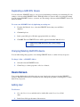
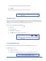
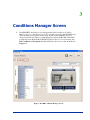
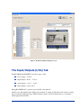
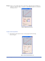
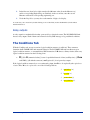
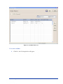
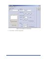
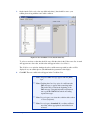
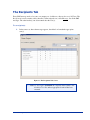
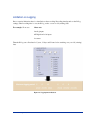
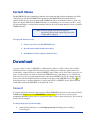
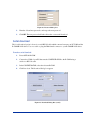
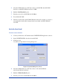
Web-site: www.remmon.com
Email: [email protected]
Tel: 972-4-6065815
Fax: 972-4-6065819
The
CONFIGURATOR
User Guide
2005© Remmon Ltd. All rights reserved
Version 1.0
i
Web-site: www.remmon.com
Email: [email protected]
Tel: 972-4-6065815
Fax: 972-4-6065819
Table of Contents
Chapter 1
Introduction......................................................................... 2
R-COM/R-LOG .............................................................................. 2
CONFIGURATOR INSTALLATION ........................................... 3
Quick Start ...................................................................................... 4
Chapter 2
Project .................................................................................. 5
Project Main screen......................................................................... 7
The R-COM Screen ........................................................................ 7
Adding GSM RTU Device ....................................................................8
Duplicating a GSM RTU device ...........................................................9
Changing/Deleting GSM RTU device...................................................9
Users Screen.................................................................................... 9
Adding User ..........................................................................................9
Duplicating User..................................................................................10
Changing/Deleting User ......................................................................10
Chapter 3
Conditions Manager Screen............................................. 12
The Input/Outputs (I/Os) Tab ....................................................... 13
Digital inputs .......................................................................................14
Analog inputs ......................................................................................14
Linear transformation table .................................................................14
Relay outputs.......................................................................................16
The Conditions Tab....................................................................... 16
Duplicating an Existing Condition ......................................................21
Changing/Deleting Condition..............................................................21
Periodic Report....................................................................................21
The Recipients Tab ....................................................................... 23
The Logger Tab............................................................................. 24
Limitation on Logging.........................................................................28
Current Values .............................................................................. 29
Chapter 4
Download ........................................................................... 29
Password..............................................................................................29
Serial download...................................................................................30
Remote download................................................................................31
Upload........................................................................................... 32
Table of Contents
ii
Chapter 5
Read/write SMS................................................................. 34
Warning......................................................................................... 34
The Set command ......................................................................... 35
Adjusting the time ...............................................................................35
The Push command....................................................................... 36
The Get Command ........................................................................ 36
Asking for time....................................................................................37
The Cancel command ................................................................... 37
Introduction
iii
First thing.
First thing first: Thank you for choosing Remmon's cellular communication device.
Remmon is committed to provide your business with the best cellular interactive monitoring solutions. If
you need further assistance please contact Remmon Remote Monitoring at: [email protected]. Or
visit our web site at www.remmon.com
About this guide
This guide provides information on how to configure Remmon GSM Remote Terminal Units (R-COM/RLog) through the CONFIGURATOR application software, it contains:
Overview on the R-COM and R-LOG units.
A step-by-step user guide on how to configure R-COM/R-LOG unit through the
CONFIGURATOR software.
Instructions on how to monitor and control R-COM using a cellular phone.
To get further information on the R-COM/R-LOG device(s), please refers to the R-COM Installation
Guide.
Audience
This guide is a technical user manual, it was written for system integrators. The reader assumes to have a
prior knowledge on control systems. No prior knowledge about Remmon’s products is needed.
Notational Conventions
Table 1: Document Conventions
Icon
Type
Description
Information Note
Important information that you should review before continuing.
Warning
Alerts you to the presence of important operating instructions.
Caution
Warns of possible damage to the equipment if a procedure is not
followed correctly.
Introduction
1
1
Introduction
R-COM/R-LOG
An R-COM is a GSM Remote Terminal Unit (RTU) device. It can monitor and control various amount of
activities either through cellular phone or through the internet. It can send/receive data from any cell
phone it is based on the popular GSM wireless communications standard. It needs to contain a SIM card
in it, which enable it to communicate through the cellular network. An R-Log is an R-COM with a built in
Data-Logger, for storing data.
The R-COM/R-Log system provides an ideal solution for interactive remote controlling. It can give you
real time information and enable you to take immediate actions through your cellular phone. In addition,
the R-Log device can store data that can be viewed later on.
R-COM specifications:
Size: 10.6 X 6.3 X 9cm.
8 digital inputs
6 analog inputs
2 relay outputs
1 RS232 port
Introduction
2
Figure 1: R-COM – Front View
To get further details please refer to the R-COM installation guide.
CONFIGURATOR INSTALLATION
The CONFIGURATOR operates under Microsoft Windows 2000 and above. It provides a full, user
friendly, graphical interface to configure the R-COM/R-LOG device(s).
Before you begin the installation please close all open windows.
1.
Insert the CONFIGURATOR installation CD-ROM to your CD drive. The setup
screen should automatically appear. Else you can manually run "Setup.exe" from the
CONFIGURATOR installation files.
2.
Follow the onscreen instructions to install the application.
To run the program click on start->Remmon remote monitoring->CONFIGURATOR.
Introduction
Note: When you run the CONFIGURATOR for the first
time you will be asked to enter a secondary
language, the SMS language will be set
accordingly. This setting is reversible, you can
change it by going to the menu bar and clicking on
Project>Language… then, in the opening dialog
box, select a language.
3
Quick Start
The CONFIGURATOR is a stand alone tool for building and configuring multiple GSM RTU devices
in various forms. It configures these devices through the CONFIGURATOR project.
Quick Start:
1
Run the CONFIGURATOR.
2
Create new project or open an existing one. (See P. “ ”).
3
Add a new GSM RTU (R-COM or R-Log) or open an existing one. (See P. “”).
4
For each R-COM:
4.1
Add/Del new user(s) or Edit existing one. (See P. “Adding User”).
4.2
Rename the R-COM's I/Os as needed. (See P. “Renaming an I/O”).
4.3
Define the conditions. (See P. “”).
4.4
Associate the users as conditions recipients. (See P. Select condition’s recipients”).
4.5
Download the project to the R-COM. (See P. “Downloading Data to an
R-COM”).
4
2
Project
A CONFIGURATOR project (or simply a project) is a set of computer files. The CONFIGURATOR can
either create a new project or open an existing one. Every project consists of a directory file and a heading
file, which has a “cgr” extension. Both the heading file and the directory file have the same name. A
project is the CONFIGURATOR basic working environment. It is a platform which enables data
streaming between GSM RTU device(s) and your settings.
When you run the CONFIGURATOR the following screen appears.
Figure 2: CONFIGURATOR Welcome Screen.
To create a new project:
1. If you are in the CONFIGURATOR welcome screen, click on New. Else click on File->New
project…
2. On the Save As pop up window: choose a directory and enter a name for your project.
5
3. When you run the CONFIGURATOR for the very first time you need to select the language
that will be used in values, names and SMS text.
To open an existing project:
1. If you are in the CONFIGURATOR welcome screen, click on Browse. Else click on File>Open project…
2. On the opening window: select your project heading file name (cgr file type).
Note: The default directory for saving a project (heading
and directory) is My Document.
Note: Only one project can be opened in each session.
Opening a project while working another one, will
cause the CONFIGURATOR to save and close the
first project, before opening the new one.
To open recent project:
1. On the CONFIGURATOR welcome screen click on Last.
While creating a new project one can import all the settings from an existing project.
To create a new project which maintain all the settings of an existing one:
1.
Open your existing project.
2.
Click File>Save as…
3.
On the Save As window: select a directory then type a name for your project (at the
File name tab) and click on Save.
Project
6
Project Main screen
This screen is the project’s top view. It consists of two screens the Users screen and the R-COMs screen.
Figure 3: Project Main Screen.
The above picture illustrates the project main screen. In the top left corner, circled in red, one can find the
project name. The Users screen which is bounded with a yellow rectangle, in the above picture, can be
found in the left corner. Whereas the R-COMs screen, bounded with a green rectangle in the above
picture, can be found in the right corner.
The R-COM Screen
With the R-COM Screen you can add new GSM RTU device(s) (R-COM/R-Log) to your project, change
their properties or delete them. You can select a GSM RTU item from the list in the R-COM Screen Table
open it, change its settings, download its data to a physical GSM RTU device or upload data from a
physical GSM RTU device into it.
Project
7
Adding GSM RTU Device
To add new GSM termminal device to your project:
1.
Go to the R-COMs Screen and click Add or double click on the R-COMs Screen Table
sheet.
2.
In the opened dialog box you can either check the SMS R-COM box for adding an RCOM unit, or you can check the Logger R-LOG box for adding an R-LOG device.
Figure 4: Adding new R-COM.
Figure 5: Adding new R-LOG.
3.
In the Name field, type a name for your added GSM RTU device.
4.
In the Phone field, type the number of the SIM card which has been added to your
GSM RTU device.
5.
Click OK.
The new added GSM RTU device should appear in the R-COM Screen Table List.
Note: To get the SIM card number (CSD), contact your
cellular service provider.
Project
8
Duplicating a GSM RTU Device
You can add a new GSM RTU device to your project by duplicating an existing one, transferring all of its
settings, to the new added GSM RTU device. With this feature you can save time on copying the settings
from an existing GSM RTU device to your new one. The settings of the new added GSM RTU device can
then be modified.
To create a new GSM RTU device by duplicating an existing one:
1.
From the R-COM table sheet, select the GSM RTU device that you would like to
duplicate.
2.
Click on Duplicate.
3.
In the opened dialog box, fill in the appropriate fields (see Adding).
4.
Click OK. The new GSM RTU device will be appeared in the R-COM table sheet.
Note: Every GSM RTU device has to have a unique
name.
Changing/Deleting GSM RTU device
You can either change the properties of an existing GSM RTU device or delete it from your project.
To change / delete - a GSM RTU dehvice:
4.
Select the relevant GSM RTU device.
5.
Click Change to edit its properties or Delete to delete it.
Users Screen
Users are the cellular phone subscribers who can control and receive messages from the GSM RTU
device(s). With the User Screen you can add new users, change the properties of existing users or delete
them from your project.
Adding User
To add a user:
1.
Go to the User’s Screen and click Add or double click on the Users Screen Table
sheet.
2.
In the Name field, type the name of the new user.
Project
9
3.
In the Phone field, type the cellular phone number of the user.
4.
Click OK.
The new added user should appear in the User Screen Table List.
Note: Do not forget to download data to the relevant GSM
RTU device.
Duplicating User
It is possible to add new user by duplicating existing one, all the condition(s) which had been associated
with this user will be set for the new user. With this feature you can save time on copying settings from an
existing user to new one. The settings of the new user can then be modified.
To create new user by duplicating an existing one:
1.
Select a User.
2.
Click on Duplicate.
3.
Fill in the fields as described in .
4.
Click OK. The new User appears in the Users List.
Note: Each user has to have a unique Name and Number
Note: Do not forget to download data to the relevant GSM
RTU device.
Changing/Deleting User
You can either change the properties of an existing user or delete him/her from your project.
To change /delete - a User:
1.
Select the relevant User.
2.
Click Change to edit his/her properties or Delete to delete him/her from the project.
Note: No changes will take effect before downloading
them to the physical GSM RTU devices.
Project
10
Project
11
3
Conditions Manager Screen
1.
Each GSM RTU device has its own settings which can be found in its Condition
Manager Screen (or Conditions Screen). To open this screen, go to the R-COM Screen
Table, and then you may either double-click on the relevant GSM RTU device or
select it and click open. There is a slight difference between the R-COM and R-LOG
Condition Screens. Both the R-COM and R-LOG Conditions Screens have three tabs
I/O, Conditions and Recipients. But the R-LOG Conditions Screen has an additional
Logger tab.
Figure 6: R-COM Conditions Manager Screen.
Conditions Manager Screen
12
Figure 7: R-LOG Conditions Manager Screen.
The Input/Outputs (I/Os) Tab
The R-COM/R-LOG GSM RTU device has 4 types of I/O:
Power supply – 12-24V.
Digital Inputs – D-in 1 … D-in 8.
Analog Inputs – A-in 1 … A-in 6.
Relay Outputs – Out 1, Out 2.
During R-COM/R-LOG’s operation, it periodically scans them all.
All I/Os come with default names which can be renamed. To rename an I/O check its tab and type a name.
On receiving and sending messages (SMSs) the I/O(s) will be referred by their name(s), i.e. the names
which appear in the I/O table.
Conditions Manager Screen
13
Digital inputs
The R-COM/R-LOG unit has 8 digital inputs D1-D8. All the digital inputs in the R-COM/R-LOG unit
return two values 0 or 1. A digital input returns 1 if it gets more than 6 volts, else it returns 0.
Note: In the R-LOG, digital input can serve as a counter as
well.
Analog inputs
The R-COM/R-LOG unit has 6 analog inputs A1-A6.
•
Inputs A1, A2 measure values at a scale range of 0 to 10 volts.
•
Inputs A3, A4 measures value at a scale range of 0 to 20 milli-ampere (mA).
•
Inputs A5, A6 are design to work with the Platinum resistance thermometers (pt100) sensor.
Linear transformation table
An analog input gets data from a sensor device and measures a scalar value (volts, milli-ampere or
resistance) it than returns an integer value ranging from 0 to 65535 (0-FFFF hex) to the R-COM/R-LOG
unit. In order to convert the returned integer value to a proper engineering measurement value one has to
use the linear transformation table. With the linear transformation table, you can create a linear (one to
one) map from M={0,1,2,…,655353} (the Measure set) to a set of your desired engineering values
(Engineering set). To create this linear map, choose two different values from the Measure set and
correspond one value to each of them. For example, in figure (), the returned value of analog input 2
(temp) has been converted to the Celsius measurement engineering scale. The initial returned values 0 and
65535 has been mapped to -40 and 60 in correspondence. The appropriate linear transformation will be
f(x)=(100/65535)x-40. To make thing clearer, consider the following example:
Conditions Manager Screen
14
Example: Suppose a sensor, which output 4 mA at a temperature of -50 Celsius degree and 20 mA at a
temperature of 50 Celsius degree, is attached to your R-COM/R-LOG unit. You can make the
following conversion:
Figure 8: Engineering Conversion
To define a linear transformation:
1.
Check the linear transformation box next to an analog input name. The following
window will appear.
Figure 9: Linear Transformation Screen.
Conditions Manager Screen
15
2.
In the first raw (from left to right) enter the first Measure value (from the Measure set)
and its corresponding Engineering one. Similarly, in the second raw, enter the second
Measure value and its corresponding engineering one.
3.
Under the Digit Show you may choose the number of digit to be display.
You can reset your conversion by double clicking on one of the fields (not the checkmark-box) in the Linear
Transformation box.
Relay outputs
A relay output is a mechanical device that opens and closes electrical contact. The R-COM/R-LOG unit
has two relay outputs. Each of them can be turned on/off by SMS message or by predefined conditions.
The Conditions Tab
With the Condition tab one can set various logical condition sentences (conditions). These sentences
determine the R-COM/R-LOG unit automatic behavior. The R-COM/R-LOG unit can either act upon
logical condition sentence or on manual direct SMS instructions. If R denotes a binary relation, then every
logical condition sentence has the following form:
•
If ( (I/O R
(numerical value)) is true for predefined interval of time (stability time) ), then
send SMS(s) (all with the same text) and (optionally) close/open relay outputs.
If the logical condition sentence does not contain analog input, then R is to be replaced by the equivalence
relation. Else, R is to be replaced by one of the following relations:
1. equivalence (=)
2. less than (<)
3. greater than (>)
4. not equivalent (≠)
Conditions Manager Screen
16
Figure 10: Condition Tab Screen.
To set a new condition:
1.
Click New, the following window will appear.
Conditions Manager Screen
17
Figure 11: New Condition Screen (General tab).
2.
Follow Table 2, to fill in the required fields.
Conditions Manager Screen
18
Table 2: New Condition Dialog Box – General Tab Fields
Field
Description
SMS
The SMS text, to be sent to the User(s).
Flash to screen
Select this option if you want the message to automatically appear on the
cellular phone’s screen.
Note: Use it only if both the R-COM/R-LOG and the Users share the
same cellular service provider.
Logical condition
A box inside the New condition screen, which enable one to set the conditional
part in the Logical Condition Sentence.
I/O
A drop-down list, listing all I/Os (Inputs/Outputs). It contains additional
items such as time and date.
A drop-down list, listing the Relations.
= equal to
=
Equal to the specific value.
>
Greater than the specific value.
<
Less than the specific value.
<> Not equal to the specific value.
Value
The rightmost space in the Logical Condition field for entering the second term
of the binary relation.
Stability time:
A box, inside the New condition screen, for setting a time interval. For the SMS
to be sent the expression inside the Logical Condition field needs to be true for
the whole time interval.
Sending settings:
A box, inside the New condition screen, for determining the number of time and
frequency, SMS message(s) is to be sent.
Up to ___ times
The number of times, SMS message is to be sent.
Every
Time frequency for SMS warnings to be sent.
Mark this option if you want to cancel repeated SMS messages.
Canceling option
Outputs
Out 1/2
Wait stability time
Conditions Manager Screen
Note: checking this box will cause the SMS
messages to appear with a canceling index.
This index can be found at the beginning of
the SMS message. Using this index the
recipient user can stop the R-COM/R-LOG
unit from sending repeated messages.
A box, inside the New condition screen, for setting the output relays.
Setting the output behavior when the first part of the Logical Conditional sentence
is true.
Time delays before the output relay close/open.
19
3.
On the Attach Values tab, select any additional value(s) that should be sent to your
cellular phone along with the text for this condition.
Figure 12: New Condition Screen (Attach values tab).
To select or unselect a value that should be sent, click the value in the Values name list. A mark
will appear next to the value, and the value will appear in the selected list too.
The Cellular screen window simulates how the condition message with its value s will be
displayed on your cellular phone. (The ### marks the parameters value digits).
4.
Click OK. The new condition should appear in the Conditions List.
Note: A repeated SMS message appears with the [REP]
sign.
Note: Checking the Canceling option box will cause the
SMS messages to appear with a canceling index.
This index can be found at the beginning of the
SMS message. Using this index the recipient user
can stop the R-COM/R-LOG unit from sending
repeated messages.
Note: Do not forget to associate the condition with a subset
of Users (recipients).
Note: Do not forget to download! No condition will have
any effect, unless appropriate download has been
executed.
Conditions Manager Screen
20
Duplicating an Existing Condition
You can add a new condition by duplicating an existing one, transferring all of its settings to the new
added condition. With this feature you can save time on copying the settings from an existing condition to
your new one. The settings of the new added condition can then be modified.
To duplicate existing condition:
1.
Click on a condition to select it.
2.
Click on the Duplicate button near the Conditions list.
3.
(optional) Change the relevant fields as described in Table 2.
4.
Click OK. The new condition should appear in the Conditions List.
Note: Do not forget to associate condition with subset of
Users (recipients).
Note: Do not forget to download! Added condition(s)
have no effect, unless appropriate download has
been executed.
Changing/Deleting Condition
To stop the R-COM/R-LOG unit device from sending warning messages over a particular condition, you
can either modify the condition or delete it.
To change / delete - a condition:
1.
Select the relevant condition from the Conditions List.
2.
Click Change or Delete button near the Conditions list.
Note: Do not forget to download! Modifications have no
effect, unless appropriate download has been
executed.
Periodic Report
To have a periodic status indication over your system, you may set condition(s) which will automatically
send SMS to a specific subset of Users (recipient(s)). With this feature you get a Keep-alive indication as
well as parameter value status report over your system.
For example one may set a condition that produce:
Daily report.
Conditions Manager Screen
21
Weekly report.
To produce a daily report:
1.
Go to the Condition Manager screen and click on the Conditions tab.
2.
Click New.
3.
In the I/O field, select Time.
4.
Adjust the hour (hrs) and min (min) fields
5.
Fill in the other fields as in the case of regular condition.
To produce Weekly report:
1.
Go to the Condition Manager screen and click on the Conditions tab.
2.
Click New.
3.
At the rightmost field in the Logical condition box, select a day.
4.
In the “At time” field adjust the hour and minute fields.
5.
Enter your requested day and time.
6.
Fill in the other fields as in the case of regular condition.
Note: when the R-COM/R-LOG unit is powered down, its
internal clock reset. In this case you can adjust its
clock by sending SMS (see Ch. Error! Reference
source not found.).
Note: No report is to be produced on the very same day
when download occurs.
Note: Do not forget to download! No modification(s) will
have any effect, unless appropriate download has
been executed.
Conditions Manager Screen
22
The Recipients Tab
Every SMS message needs to be sent to a nonempty set of addressee, subset to the set of all Users. The
Recipient tab screen contains a table, the table’s leftmost header row, called Message, list all the SMS
messages. The other header(s) raw is/are named after the User(s).
To set recipient(s):
1.
In the same row, where the message appears, check the box beneath the appropriate
user(s).
Figure 13: The Recipients Tab Screen.
Note: Do not forget to download! No recipient will be added to the
Condition User List, unless appropriate download has been
executed.
Conditions Manager Screen
23
The Logger Tab
The Data-Logger, as its name suggests, stores data. The R-Log is an R-COM with a built in Data-Logger.
In can store up to 18 MB. It can collect data from its analog inputs and from its digital inputs. Thus, by
collecting data from digital input it can serve as a counter. The collected data are kept in file which can be
viewed by using MS-Excel.
Figure 14: The Logger Screen Tab.
To change settings check the Loading definition box, this will issue a warning about a possible data lost.
For the sake of clarification we have divided the Logger Tab Screen into 6 sections, as shown in the
following figure.
Conditions Manager Screen
24
Figure 15: Logger tab screen.
A – Set a time interval for collecting data.
B – Logging time indicator (before overwriting occurs).
C - Six Analog inputs.
D - 8 Digital inputs and the Volt input.
E - 8 internal counters
F- Loading R-Log’s stored data and putting it in a graph.
Load: To get data from the R-Log to your computer click browse and choose a directory and
file name (for example: you may call your file foo ) , you may choose between csv and xls file
type extension. Click LOAD, in the prompted window, choose your Com, Baud rate, and
stream (serial or cellular) and then fill in your password (the default password is
000000000000). Click on start to begin with the loading.
Show: The file foo.csv or foo.xls can be viewed by MS-Excel, however the CONFIGURATOR
allow you to view it graphically. To get a graphical view click on SHOW, a screen with three
upper tabs appears.
Conditions Manager Screen
25
Figure 16: Analog Input Tab.
Figure 17: Digital Inputs Tab.
Conditions Manager Screen
26
Figure 18: Counters Tab.
Zooming: The zoom level of a selected region could be changed by dragging the pointer to
create a rectangle.
Zoom up: To zoom up start dragging a rectangle from the left upper side, the area inside the
rectangle will be zoomed.
To return to regular view, start dragging a rectangle from the lower right side.
Navigating: To navigate through the graph hold the mouse right button while moving your
mouse.
Conditions Manager Screen
27
Limitation on Logging
Due to capacity limitation, there is a time limit on data recording. Recording time depends on the R-Log
settings, when recording time is over, the R-Log writes over an on old (existing) data.
For example: If one sets
1 hour rate
4 analog inputs
All Digital and volts inputs
4 counters
Then the R-Log can collect data for 5 years, 13 days and 5 hours before rewriting over your old (existing)
data.
Figure 19: Logging time indication.
Conditions Manager Screen
28
Current Values
The R-COM/R-LOG unit communicates with the environment through its Input and Outputs exits. Each
of these I/Os provide the R-COM/R-LOG with data, the R-COM/R-LOG transform this data into
numerical value. In every given moment the R-COM/R-LOG unit stores numerical values for each of its
inputs and outputs. While the R-COM/R-LOG unit is on and running, you can connect your PC to it and
get an instant display, to display all the numerical values at the exact moment when have been stored in RCOM/R-LOG unit.
Note: If an analog input value had been mapped to
engineering value, then the engineering value is the
one that will be displayed.
To display the numerical value:
1. Connect your PC to your R-COM/R-LOG unit .
2. Open the project which includes these unit(s).
3. In the Menu bar click on Options>Current values…
Download
A project consists of a list of GSM RTU(s), which had been added to it. Each of these devices will be
called Project Item, or simply Item. The project itself is nothing but a computer program it needs to be
downloaded to a physical device(s), namely GSM RTU device. When you are done with your project, you
need to download each of its items to the relevant GSM RTU device. Any changes to one of the Project
Item need to be follow by downloading the Item to the relevant GSM RTU device. No changes will take
icon
effect, unless the relevant Item had been downloaded to the appropriate GSM RTU device. The
should appear next to any Item which has not been downloaded to a GSM RTU device. Each download
synchronizes between the GSM RTU clock and the PC clock.
Password
To execute download you need to enter a password. Each GSM RTU device has its own password. The RCOM/R-LOG default password is 000000000000 (12 times zero). You can save your password by
checking the Remember password box your password will be saved for future download(s). The download
password can be changed.
To change the password for downloading:
1.
Download
On the Download dialog box, click Change password, the Change password dialog
box will appear.
29
Figure 20: Password dialog box.
2.
Enter the old and new passwords, and retype the new password.
3.
Click OK. The new password will take effect after a successful download.
Serial download
This local download option is done via a serial RS-232 cable which connects between your PC COM and the
R-COM/R-LOG device. Use cross cable to plug the DB9 female connector to your R-COM/R-LOG device.
To make a serial download:
1.
Power-OFF the R-COM.
2.
Connect free COM of your PC that runs the CONFIGURATOR to the R-COM using a
serial cross RS-232 cable.
3.
In the CONFIGURATOR, select the relevant R-COM.
4.
Click Download. The Download dialog box appears
Figure 21: Download Dialog Box (serial).
Download
30
5.
Select the COM number in your PC that connects to the R-COM and the R-COM’s
baud rate; a standard R-COM use baud rate of 9600.
6.
Mark the Serial Download option.
7.
Enter the password for the R-COM and click Start.
8.
Power-ON the R-COM.
9.
The data is downloaded to the R-COM. When the download is complete, you receive a
message that the download has been performed successfully, and the R-COM will
reset itself.
Remote download
To make a remote download:
1.
Connect your Modem to a PC which runs the CONFIGURATOR application software.
2.
In the CONFIGURATOR, select the relevant R-COM.
3.
Click Download.
You will be prompt with the following dialogue box.
Figure 22: Download Dialog Box (remote).
4.
Select the COM number in your PC that connects to the standard Modem
and select the Modem’s baud rate.
5.
Mark the Cellular Download option.
6.
Enter the password for the R-COM and click Start.
Download
31
Note: The default password is 000000000000
(12 times
zeros).
7.
The data is downloaded to the R-COM. When the download is complete, you receive a
message that the download has been performed successfully.
Preparing for Remote download
In order to support communication between CONFIGURATOR and R-COM, a cellular modem needs to
be connected to a PC which runs the CONFIGURATOR application software.
Note: Make sure that the both the R-COM/R-LOG SIM
and the PC modem’s SIM support CSD
communication.
Note: If the R-COM/R-LOG SIM and the PC modem SIM
are from different cellular service providers, use the
DATA-IN number (the phone number for using the
CSD) as the R-COM number.
Ask your cellular service provider for the SIM
card CSD. Your cellular provider will give you
information about the DATA-IN number.
Setting up the Cellular Modem
Before you connect the cellular modem to the PC, insert the SIM card into the modem so that the modem
can transmit and receive data via the cellular network. For instructions regarding installation of the SIM
card, refer to the modem’s documentation.
Connect the modem to the PC using a 9 pin D-shell cable.
To connect the modem to the PC:
1.
Connect the female end of the 9 pin D-shell cable to the PC that is running
CONFIGURATOR.
2.
Connect the male end of the cable to the cellular modem.
Upload
Transferring data from a project to a GSM RTU device can be done by download. However data can be
transferred from the GSM RTU device to the project, this process is called upload. You can upload data
from a GSM RTU device to one of the Project item, referred here by the name foo. If the upload
succeeded, then both the GSM RTU device and foo will have the same data.
Download
32
To upload data to a project item:
Download
1.
Select a project item.
2.
Click upload and fill in the fields as in the case of download.
3.
Click start and proceed as in the case of download.
33
4
Read/write SMS
This chapter provides information on how to read and write SMS message(s). The R-COM/R-LOG device
allows to:
Receive warnings and reports.
Close/Open relay output.
Close/Open relay output for a predefined interval of time.
Receive a value.
Stop repeated warning.
Note: To control and monitor your R-COM/R-LOG device
your cellular phone has to be in the R-COM/R-LOG
User List
Warning
When the conditional part (first part) of a logical condition sentence becomes true, the R-COM/R-LOG
executes the second part, thus sends a warning (SMS) to all cellular phone(s) which have been set as
recipient Users for this condition. The warning SMS message appears in the following form:
<index #>:<SMS Text>
Where
• <index #> is the index number of the condition.
• <SMS Text> is the warning which had been dictated when condition has
been set in the CONFIGURATOR project.
Example: Consider the Demo Project an R-COM has been set to monitor over a Swimming-pool, see Fig
10. The second condition is saying that if the analog input called WaterTmp drops bellow 20
Celsius degree, then send an SMS warning which saying that “Heat is on”. The SMS will
display in the following form:
2: Heat is on.
Read/write SMS
34
Note: If the Flash to screen option was selected for this
condition, the message automatically appears on the
cellular phone’s screen.
Note: If a warning is sent more than once, [REP] is
displayed on the cellular screen next to each
subsequent condition message. To stop repeated
message, use the cancel command.
The Set command
With the set command you can either close/open a relay output or adjust R-COM/R-LOG’s clock. Each
User can close\open a relay output by sending an SMS with the following form:
set:<Output name>=<value>;
Where <Output name> is the name of the relay output and <value> can either be replaced by 1 (close) or 0
(open). The arguments of the set command may be concatenated in the following form:
set: <Output name-1>=<value-1>;<Output name-2>=<value-2>;
Example: Consider the Swim-pool R-COM which has been defined in the Demo-Project. The relay
output names are Pump and HeatSys. To turn on the pump send an SMS with the following
text:
set:Pump=1;
To turn the Pump off and start the heat system (HeatSys) you can send one SMS with the
following text:
set:pump=0;HeatSys=1;
Adjusting the time
To adjust the R-COM/R-LOG internal clock send an SMS with the following form:
set:time=HH:MM;date=dd.mm.yy;
where HH is the hour, MM are the minutes, dd is the day, mm is the month and yy is the year.
Example: If one wants to set R-COM/R-LOG’s date to 17:56 January 28, 2007, then the SMS to be sent
is:
set:time=17:56;date=28,01,07;
Read/write SMS
35
Note: The SMS should be sent to the SIM card number
which has been inserted to the R-COM/R-LOG
device.
Note: Every User can use the set command.
Note: A confirmation will be sent to the User who sent
the SMS.
The Push command
With the push command one can close/open the relay output(s) for a predefined interval of time. The push
command should be sent in the following form:
push:<O#>,<value>,<period>;
Where < O#> replaced by the relay output NUMBER (O1 or O2), <value> replaced by 1 (close) or 0
(open), and <period> replaced by a number which determine the time interval in seconds.
The arguments of the set command may be concatenated in the following form:
push: <O1>,<value1>,<period1>;<O2>,<value2>,<period2>
Note: After R-COM changes the value, the following
notification message will be sent to your cellular
phone: “Success of push:
push:<Output_name>,<value>,<period>;”
Example: Consider the Swim-pool R-COM which has been defined in the Demo-Project. The name of the
first output is Pump, the name of the second output is HeatSys. To turn on the pump, that is to
close the Pump relay output, for 60 seconds a User needs to send an SMS with the following
text:
push:O1,1,60;
The Get Command
With the get command you can either ask the R-COM/R-LOG device to send you the current value of
each of its I/O or ask for its internal time and date. The get command should be sent in the following form:
get:<I/O name>;
When you send the get command to the R-COM/R-LOG device it should respond by sending you an
SMS message which contains the value you asked for. The arguments of the get command may be
concatenated in the following form:
Read/write SMS
36
get:<I/O name1>;<I/O name2>;<I/O name3>;
Example: Consider the Swim-pool R-COM which has been defined in the Demo-Project. The name of
one of its analog input is WaterTmp. To verify the water temperature status you can send the
following text:
get:WaterTmp;
The R-COM should reply with an SMS which contains the water temperature (current value of
the analog input).
Asking for time
To ask the R-COM/R-LOG for its internal date send the following text:
get:date;
R-COM/R-LOG should respond with SMS displaying its internal date.
To ask the R-COM/R-LOG for its internal time send the following text:
get:time;
R-COM/R-LOG should respond with SMS displaying its internal time.
The Cancel command
With the cancel command you can stop repeated warning from repeating itself. The cancel command
should be sent in the following form:
cancel: <index #>;
Where < index #> is the index number of the condition for which you want to stop.
Note: After R-COM cancels the warning, the following
notification message is sent to your cellular phone:
“cancelled <SMS Text>;”
Read/write SMS
37