1
DriveWare 300 Startup Guide
Rev 3.0.3a
1
Table Of Contents
Table Of Contents ............................................................................................................. 2
Foreword............................................................................................................................ 3
Connecting to the Drive.................................................................................................... 4
Drive Parameter Configuration....................................................................................... 6
User Units ....................................................................................................................... 7
Motor Data and Primary Feedback ............................................................................... 11
Motor Constants........................................................................................................ 12
Feedback ....................................................................................................................... 16
Velocity Feedback..................................................................................................... 16
Position Feedback..................................................................................................... 17
Drive Configuration ...................................................................................................... 18
Drive Current Limits................................................................................................. 19
Voltage Limits ........................................................................................................... 20
Velocity Limits .......................................................................................................... 21
Position limits ........................................................................................................... 22
Temperature Settings ................................................................................................ 24
Power-up Control ..................................................................................................... 25
Braking...................................................................................................................... 26
Tuning and Commutation.............................................................................................. 27
Current Loop Tuning .................................................................................................... 28
Commutation................................................................................................................. 34
AutoCommutation™ Detection................................................................................. 35
Manual Commutation Procedure ............................................................................. 39
Velocity Loop Tuning................................................................................................... 42
Position Loop Tuning ................................................................................................... 48
Command Input and Scaling ......................................................................................... 54
Command Source.......................................................................................................... 55
I/O Configuration.......................................................................................................... 59
Appendix.......................................................................................................................... 63
Digital Scope................................................................................................................. 64
Waveform Generator .................................................................................................... 68
Command Profiler......................................................................................................... 70
Signal Definitions ......................................................................................................... 73
Drive Status................................................................................................................... 78
Drive Control ................................................................................................................ 83
2
Foreword
This startup guide will provide an overview of connection and basic setup instructions for
Advanced Motion Controls 300 series drives using the DriveWare 300 software. The
basic setup of a digital drive is designed to be analogous to the setup and tuning of an
analog amplifier. These instructions will walk you through the following steps necessary
to start up your drive and motor. All information within this document can be found in
the help files included with DriveWare 300. This document is intended for setting up the
drive. The help files contain more detailed information not included in this document.
The following major sections are covered:
1.
2.
3.
4.
Connecting to the Drive
Drive Parameter Configuration
Tuning and Commutation
Command Input and Scaling
3
Connecting to the Drive
You may open the 'Connect To Drive' window by selecting Connect To Drive when
DriveWare is started. You can also open it by selecting Communication > Connect on
the menu bar, or by clicking
on the toolbar. You must initially connect to the drive
using the factory default settings stored in nonvolatile memory and the appropriate serial
port selected from the PC. Once communication is established, you may change the
address and baud rate settings by going back into the Connect To Drive
window, choosing your desired settings, and hitting Connect. The new settings will take
effect immediately. In order to retain the new settings upon power-up, they must be
stored in nonvolatile memory (see Communication, Store).
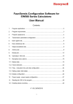
The following window appears when Connect
is selected from the toolbar or file
menu or when Connect to drive is selected from the opening page.
Connect To Drive Window
•
•
•
•
PC Interface Settings: Selects the type of communication used
between the drive and PC.
Drive Address: Selects the address of the drive that is connected to the PC. The
factory default setting is 63, where the valid range of addresses is 1 - 63.
PC Interface Settings: When selected, a new screen pops up and allows you
to select the appropriate serial port and baud rate (see PC Interface Settings
Window below).
Connect: Establishes a connection with the specified settings. When connecting,
you can choose to download the current project settings to the drive, or to upload
the stored drive settings into the project. The status bar in the lower right corner of
DriveWare will change from NOT CONNECTED to CONNECTED.
4
•
•
•
Cancel: Closes the connection window without connecting.
Help: Brings up the help document.
Exclusive Control: This checkbox should always be checked when configuring
your drive through DriveWare. For CANopen drives (ZDCR and DCR drives),
you may uncheck the box to put DriveWare in a read-only state that allows
monitoring through DriveWare while writing to through the CANopen interface.
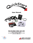
PC Interface Settings Window
•
•
•
PC Serial Port: Selects the serial communication port to which the drive is
connected. The factory default setting is COM1
Baud Rate: Selects the communication baud rate. The factory default setting is
9600.
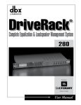
Auto Detect: This button allows you to automatically detect the serial port and
baud rate stored in your drive. When this button is selected, the screen shown
below will pop up. Select Start Scan ... and wait for the program to go through
the detection routine. After successful detection, select Apply Settings. Note: a
drive must be properly connected to a serial communication port of the PC for
proper detection.
Auto Detect Window
5
Drive Parameter Configuration
This is the first step in configuring the drive. In order to tune and commutate a motor, the
drive must have information about scale factors, feedback devices, motor parameters, and
limits. In DriveWare, each of the windows in the table below must be filled out with
accurate data.
The easiest way to configure a new drive, or one that has had a factory default project file
downloaded to it is to use the Drive Configuration Wizard . The wizard walks you
through each of the necessary windows to configure the drive parameters. Once the
wizard is complete, the drive will be ready for Command Input and Scaling. To use the
wizard, select Tools > Wizard on the main menu bar, or click on the drive configuration
wizard icon , otherwise find each of the following tables in the DriveWare
software and fill in the appropriate information.
It is not required to use the wizard to configure your drive. The table below shows where
to find each window in the setup software.
DriveWare Window
Navigation when not using Wizard
User Units
Options > User Units
Motor Data and Primary Feedback
Main Block diagram > Motor Data block > Motor
Constants tab
Load Data /Feedback
Main Block diagram > Load Data block
Feedback
Main Block diagram > Motor Data block > Primary
Feedback tab
Main Block diagram > General Drive
Configuration
It is left to the user to click through the tabs and fill in the appropriate data once the
wizard navigates to a window.
Drive Configuration
6
User Units
The User Units window allows you to select which units you would like to use for your
motor and load. This makes it easier, for example, to track your motor speed in RPM
while you track your load speed in m/s. A variety of units are selectable, and even custom
units may be defined and used. The User Units window is selected by going to Options >
User Units on the main file menu.
Settings Tab
The settings tab allows you to set the general units you will use in DriveWare300. Select
the type of unit (Distance, Time, etc) from the Unit Type drop down menu. Select the
corresponding units from the Default Unit dropdown menu.
You may also define custom units by selecting 'Custom (x)' under the Default Unit
dropdown menu. Once selected, you may choose any name you like to define your
custom units.
7
8
Default Motor Units Tab
The motor tab allows you to select the units that correspond to your motor. The
dropdown menu includes common units as well as any custom unit you may have defined
in the settings tab.
9
Load Units Tab
The load units tab allows you to define which units will describe your load. If you are
using a gearbox, you may select the gearbox checkbox to automatically assign gear ratios
to the units.
10
Motor Data and Primary Feedback
The motor data and primary feedback windows can be accessed by clicking on their
corresponding icons in the main block diagram.
Motor Data
•
The motor data will be stored in the drive and the project file and can also be
stored in the motor database.
Manufacturer
The name of the motor manufacturer.
Model
The motor model
Motor Type
The type of motor used. The brush and brushless motor types pertain to rotary
motors. The linear brushless motor type pertains to linear motors.
Feedback
Model
The name of the type of feedback to be used with the motor
11
Motor Constants
12
•
Under the Motor Constants tab, the following information can be entered:
The voltage constant corresponds to the motor back-EMF constant. This value
can be obtained from the motor data sheet. The numerical value and units can
Voltage Constant
be selected independently (the numerical value will NOT be re-calculated
when a different unit is selected).
Torque/Force
Constant
This value can be obtained from the motor data sheet. The numerical value
and units can be selected independently (the numerical value will NOT be recalculated when a different unit is selected).
Resistance
This value can be obtained from the motor data sheet. In case of brushed type
motors it corresponds to the armature resistance. In case of brushless motors it
corresponds to the phase-to-phase resistance.
Inductance
This value can be obtained from the motor data sheet. In case of brushed type
motors it corresponds to the armature inductance. In case of brushless motors
it corresponds to the phase-to-phase inductance.
Thermal Time
Constant
This value can be obtained from the motor data sheet.
Max Motor
Temperature
Maximum allowable motor temperature.
Maximum
Current
The maximum current is the peak operating current that the motor can handle.
This does not correspond to the de-magnetizing current, which is typically
much higher than the maximum operating current. This value can be obtained
from the motor data sheet.
Rated Current
The rated current is the nominal (continuous) current that the motor can
handle. This value can be obtained from the motor data sheet.
Number of
Poles/Pole Pitch
The number of poles, in case of rotary motors, corresponds to twice the
number of electrical cycles per motor revolution. The pole pitch, in case of
linear motors, corresponds to the length of one electrical cycle (360 degrees).
The numerical value and units can be selected independently (the numerical
value will NOT be re-calculated when a different unit is selected). This
information can be obtained from the motor data sheet.
Maximum Speed
The maximum speed corresponds to the maximum speed of the motor. The
numerical value and units can be selected independently (the numerical value
will NOT be re-calculated when a different unit is selected). This information
can be obtained from the motor data sheet.
Maximum
Current At Max
Velocity
Corresponds to the maximum current the motor can handle at maximum
speed. This information can be obtained from the motor data sheet
Wire
Identification
Wiring identification can be entered for each phase, by selecting wire color(s)
and/or wire labels
13
Primary Feedback
14
•
Under the Primary or Commutation Feedback tab, the following data can be
entered (model dependent):
Hall Sensors
Check the box if Hall sensors are available and connected. Also select the Hall
phasing.
Motor
Encoder
Check the box if a motor mounted encoder is connected. AutoCommutation™
Detection will determine the polarity. Enter the encoder line count per revolution
(per mm/inch for linear motor). Also indicate if there is an encoder index pulse,
and the number of index occurrences per revolution (number of lines per index
occurrence for linear motor).
Wire
Wiring identification can be entered for each connection, by selecting wire
Identification color(s) and/or wire labels
In case of resolver feedback, you may also select the resolution (12-bit means an equivalent 4096
counts/rev, 14-bit means 16384 counts/rev).
15
Feedback
The Feedback window is opened by clicking on the feedback icon in the main block
diagram. It allows selection of the feedback used by the velocity and position loops.
Velocity Feedback
•
•
•
•
•
•
Motor Mounted Encoder: the velocity is derived from the motor mounted
encoder.
Motor Mount Hall:the velocity is derived from the motor mounted hall sensors.
Analog Input: the velocity is derived from an analog input. Typically used in
case of a motor mounted tachometer. The analog signal must be conditioned not
to go outside the range of +/-10V. For drive with multiple analog inputs, click on
the
to select which analog input to use.
Interface Input: the velocity is provided over the communication interface. This
is an advanced option which is currently not available with standard drives.
Resolver: the position is derived from the motor mounted resolver.
Feedback Polarity: Represents the polarity of the selected feedback device
signal.
16
Position Feedback
•
•
•
•
•
•
•
Motor Mounted Encoder: the position is derived from the motor mounted
encoder.
Analog Input: the position is derived from an analog input. Typically used in
case of a load-mounted potentiometer. The analog signal must be conditioned not
to go outside the range of +/-10V. For drive with multiple analog inputs, click on
the
to select which analog input to use
Auxiliary Encoder: the position is derived from the auxiliary encoder input.
Click on the
to specify the ratio of input counts to position counts.
Interface Input: the position is provided over the interface.
Resolver:the position is derived from the motor mounted resolver
Feedback Polarity: Represents the polarity of the selected feedback device
signal.
Note: availability of the above selections is drive model dependent.
17
Drive Configuration
The Drive Configuration window allows configuration of general drive parameters.
These limits have associated events (see Drive Status and Drive Control). The following
tabs are available:
Drive Current Limits
Voltage Limits
Velocity Limits
Position limits
Temperature Settings
Power-up Control
Braking
18
Drive Current Limits
Sets the drive output current limits, within the hardware capabilities of the drive.
•
•
•
•
•
Peak Current: Maximum output current (limited output time).
Continuous Current: The maximum continuous current level the drive will
output.
Peak Current Time: The maximum time duration of peak current.
Foldback Time Constant: The time the drive will use to reduce the current to the
continuous current level setting.
Current Limit Scaling: You may assign an input to change the current
limit dynamically. The scaling value can be adjusted in IO Configuration.
The drive can output its rated peak current for a maximum of 2 seconds with a foldback
time of 10 seconds. This defines the maximum current capability curve. Current profiles
that intersect with the maximum current capability curve will be limited to stay within
this envelope.
19
Voltage Limits
•
•
•
Sets the user under and over voltage limits. These limits are restricted to fall
within the hardware capability of the drive. The Nominal DC Bus Voltage should
contain the normal operating DC voltage supplied to the drive. If using an
AC input drive, the Nominal DC Bus voltage is equal to the AC voltage
multiplied by 1.41.
If the drive has provision for connection of an external shunt resistor, the
parameters of that resistor can be entered. If that provision is not available, these
fields will not be available. Check the data sheet for your drive to see if an
external shunt resistor can be connected.
The shunt regulator (if available, depending on drive model) can be
enabled/disabled and its turn-ON voltage can also be set. The internal shuntresistor parameters, if present, are displayed.
20
Velocity Limits
The following velocity-related limits can be set:
•
•
•
•
•
•
Motor Over Speed: The maximum speed in which the motor should be able to
go. The action following a motor overspeed event can be defined in Drive
Control. (Active in all operating modes)
Zero Velocity Window: The measured velocity values, within which the motor is
considered to be at zero velocity (active in all operating modes)
At Velocity Window: The “At Velocity” event will be set when the measured
velocity reaches the target velocity, within the “At Velocity” window (active in
velocity mode only).
Velocity Following Error: The maximum allowed velocity error (difference
between demand velocity and measured velocity), prior to setting the “Velocity
Following Error” event (active in velocity mode only).
Positive Velocity Limit: The maximum allowed demand velocity in the positive
direction (active in velocity mode only).
Negative Velocity Limit: The maximum allowed demand velocity in the negative
direction (active in velocity mode only).
21
Position limits
The following position-related limits can be set:
•
•
•
•
•
In-Home Position Window: Defines a window around the Home Position Value,
such that when the measured position is within this window, the At-Home
Position event will be active.
In-Position Window: Defines a window around the target position, such that
when the measured position is within this window, the At Command event will be
active.
Position Following Error Window: The maximum allowed position error
(difference between demand position and measured position) prior to setting the
“Position Following Error” event (active in position mode only).
Home Position Value: Position value of the home position. When the measured
position reaches this position, within the In-Home Position Window, the At-Home
event becomes active.
Measured Position Value: Replacement value for the measured position when
the Load Measured Position event is triggered. This allows you to redefine the
current measured position (e.g. reset to zero). CAUTION: make sure the target
22
•
•
•
•
•
position is set to the proper value prior to enabling the drive. Otherwise a large
position following error will exist.
Max Measured Position Limit: Maximum allowed measured position. The Max
Measured Position event will become active if the measured position exceeds this
value.
Min Measured Position Limit: Minimum allowed measured position. The Min
Measured Position event will become active if the measured position exceeds this
value.
Max Target Position Limit: Maximum allowed target position. The Max Target
Position event will become active if the target position exceeds this value.
Min Target Position Limit: Minimum allowed target position. The Min Target
Position event will become active if the target position exceeds this value.
Disable Position Limits Checkbox: Allows you to disable position limits so the
motor has no maximum or minimum position value.
23
Temperature Settings
•
If the motor has an analog temperature sensor, it can be connected to an analog
input of the drive. The user can configure a maximum allowable motor
temperature at which point the drive will be disabled. The motor temperature
level at which the drive can be re-enabled can also be configured. The source of
the analog input can be configured as well. For a digital temperature sensor, see
I/O Configuration.
24
Power-up Control
Power-up Action
•
•
•
Phase Detect: Performs a phase-detect routine on start-up. The event is only
active when using an encoder with no hall feedback.
Load Measured Position: Loads the position defined in the position limits tab as
home position.
Load Target: Loads the target position as defined in the Command Source
window. This action is only active when operating in Encoder Following or Step
and Direction position mode.
Bridge State Following Power-up Action
•
Note: If Inhibit or Dynamic Brake is selected, you will only be able to enable the
drive using the software. To use inhibit or dynamic brake via digital inputs,
see I/O Configuration.
25
Braking
•
•
Braking: Allows you to set time delays between external braking and
enabling/inhibiting the drive. This is particularly important in applications which
the motor is holding a vertical load. The delay allows the brake to apply before
the bridge is disabled or for the brake to release after the bridge is enabled. You
may configure events to activate the brake output from within Drive Control.
Stop: When active, the Stop will decelerate the load to a stop and send a zero
command to the active loop. Events that trigger the Stop function can be
configured in Drive Control.
26
Tuning and Commutation
Drive tuning is a multi-step process that involves proper tuning of up to three different
servo loops. Before tuning, the drive should have the appropriate parameters and limits
configured as per the Drive Parameter Configuration page. Follow the steps below for
tuning and commutating your drive and motor.
Caution: Sudden motion may occur! Tuning should only be performed after motor
information and drive limits have been specified. See Drive Parameter
Configuration if you are not sure your drive is configured correctly for tuning.
Step 1: Current Loop Tuning: Once the drive parameters are configured properly, the
current loop must be tuned. This is the innermost loop and forms the basis of all motion.
You can select to have the current loop gains calculated based on motor and application
data. This will typically provide a good starting point where most applications will
require further refinement of the tuning parameters. Make sure the drive is disabled
before hitting Calculate Gains.
Step 2: AutoCommutation™ Detection: This routine collects data on the motor and
feedback parameters and asks the user to verify that they match what is entered into the
Motor Data page. It is crucial to make sure the motor is unloaded; any load applied
to the motor will skew the results of the routine. Some applications may have motors
that cannot perform this routine due to mechanical constraints. It is possible to manually
wire a motor for commutation. See Manual Commutation Procedure if you must perform
manual commutation.
Step 3: Velocity Loop Tuning: If you want to operate the drive in velocity mode, you
must tune the current loop and setup the drive to commutate the motor (steps 1 and 2). A
very tight current loop inside of a relatively tight velocity loop may cause audible white
noise. If maximum bandwidth is not necessary, de-tuning the current loop usually
removes most of the audible noise. The velocity loop will have to be adjusted any time
the curent loop tuning is changed.
Step 4: Position Loop Tuning: You can either tune the position loop around the velocity
loop, or around the current loop. Generally, it is much easier to tune a position loop
around a velocity loop because only the proportional gain is needed. When tuning
position around the current loop, a high derivative gain may be necessary on top of both
proportional and integral gains.
27
Current Loop Tuning
Caution: make sure that the motor is free to move and de-coupled from the load.
Sudden motion may occur!
Tuning of the current loop should only be performed after motor information and
drive limits have been specified.
Step 1: I/O Configuration Set Up
1. Click the I/O Configuration Block in the main block diagram
2. Select the Digital inputs tab
3. If an external Inhibit/Enable circuit is used during setup, use the check boxes to
assign the inhibit function and proper polarity (e.g. active high or active low).
4. If no external Inhibit/Enable circuit is used during setup, clear check boxes for all
inhibits. Inhibit/Enable will be controlled solely through the DriveWare
Enable/Disable Drive icon
.
28
Step 2: Current Loop Window Set Up
1. On the Main Block Diagram, click Current Loop to open the current loop tuning
parameters.
2. To set starting values for proportional and integral gains, click the Calculate
Gains button.
Note: Calculate Gains utilizes the values entered into the Motor Data and Primary
Feedback and Drive Configuration screens. The specified inductance, resistance, and bus
voltage determine accuracy of the calculated values. If accurate data is not available,
begin with the Proportional Gain = 1 and Integral Gain = 0.
29
Step 3: Waveform Generator Set Up
In the Current Loop window, click the Waveform Generator button (or select Tools -->
Waveform Generator on the menu bar) to open the Waveform Generator screen. Set up
the Waveform Generator as follows.
1. Select the Square Waveform Type.
2. Set Frequency to 100 Hz. If your motor has low inertia and is very responsive,
use 150 Hz or 200 Hz.
3. Ensure Offset is zero.
4. Ensure Symmetry is 50%.
5. Select Waveform Into The Current Loop.
6. Set the waveform amplitude to an appropriate value. Begin with 10% of the drive
continuous rating or 50% of the motor continuous current rating, whichever is
lower.
30
Step 4: Oscilloscope Set Up
On the menu bar, select Tools --> Oscilloscope (or click the oscilloscope icon on the
) to open the digital oscilloscope. Set up the scope view as follows.
toolbar
1. Assign the channel 1 signal to Iq-Target and the channel 2 signal to IqMeasured (use the "Change" button if necessary).
2. Change the Trigger Source to Torque Target with the Level set to zero.
3. Ensure Trigger Mode is Normal.
4. Change Time/Div to either 1 msec or 500 usec.
31
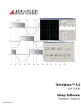
Step 5: Tuning
Position the Scope, Waveform Generator, and Current Loop windows such that a
majority of all the windows are visible as shown. The best method is to place the
oscilloscope in the lower left corner, while placing the current loop and Waveform
Generator windows in the upper and lower right corners as shown below.
•
•
Enable the drive by clicking the Enable/Disable Drive icon
Proper current loop tuning starts with zero integral gain while increasing the
proportional gain until a 'knee' is formed (with no overshoot) in the Iq-Measured
trace as shown below.
32
•
At this point, the proportional gain is done and the Integral gain must be slowly
increased to close the steady state error between the Iq-Target and Iq-Measured
traces. See below.
•
Tuning changes with signal amplitude. Therefore you should now re-adjust the
current amplitude in the waveform generator according to your most common
application current requirements and re-tune. Contouring applications
generally use small signal transients while Point-to-point applications use larger
signal transients.
Disable the drive by clicking the Enable/Disable Drive icon
.
When current loop gain adjustments are complete, click Not Connected on the
Waveform Generator to remove the command signal from the drive.
On the Menu Bar, select Communication --> Store (or click the Store Settings
icon
), then OK to store parameters to the drive nonvolatile memory.
•
•
•
33
Commutation
Motor commutation is dependant on the type of motor and feedback available from the
motor. Brushed motors have a commutator built into the motor housing; therefore the
drive does not have to be configured to commutate them. Brushless DC (Trapezoidal),
and AC (Sinusoidal), motors require a correctly configured drive to commutate. There are
two ways to configure an AMC Digiflex drive to commutate a motor.
•
AutoCommutation™ Detection : Most applications can use the autocommutation
routine for configuring a drive to a specific motor. This routine will detect the
feedback devices attached to the motor and ask the user to verify them against the
motors data sheet.
•
Manual Commutation Procedure: If your motor is mechanically restrained such
that it is not free to move 2 revolutions + 1 electrical cycle in both directions, or 3
electrical cycles for a Brushless linear motor, you will have to perform the
Manual Commutation method. This method is just as precise, but can be more
tedious.
34
AutoCommutation™ Detection
Commutation of a permanent magnet servomotor is the process that maintains an optimal
angle between the permanent magnet field and the electromagnetic field created by the
motor current(s). The AutoCommutation routine detects the motor feedback type
and polarity, then configures the drive commutation parameters appropriately. This
process ensures optimal torque or force generation at any motor speed for brushless
motors.
Brushless and linear motors with insufficient travel distance (two revolutions plus one
electrical cycle for rotary motors, or three electrical cycles for linear motors), will require
the Manual Commutation Procedure instead. AutoCommutation detection is not required
for brush-type motors.
Before you run Auto Commutation, be sure you have:
•
•
•
•
•
Entered in the correct motor information in the motor data page
Specified the correct feedback information
Specified limits to protect the motor
Tuned the current loop
De-coupled the motor from any load and secured the motor. Sudden motion
will occur!
If you have not done the preceding, see the Steps Before Operating Your Drive page.
For brushless and linear motors with sufficient travel distance, proceed as follows:
35
1. In the current loop window, select the Commutation tab.
2. Ensure Sinusoidal Commutation is selected.
3. Verify that indicated Counts per Electrical Cycle and Counts per Index values are
correct. (The primary Feedback Polarity will be determined during Auto
Commutation)
4. If drive is disabled, click the Enable/Disable Drive icon
to enable the drive.
36
5. Click Enter AutoCommutation to open the Commutation Data
window.
6. Ensure the Reacquire Commutation checkbox is checked*.
7. Click Start Auto Commutation to begin the process. During the Auto
Commutation process, monitor the distance traveled in each direction. Rotary
motors will turn two revolutions plus one electrical cycle in each direction. Linear
motors will move three electrical cycles in each direction.
8. When Auto Commutation is complete, select whether the motor has moved the
proper distance ("Yes") or has not moved the proper distance ("Edit Motor Data").
If the motor did not move the proper distance, verify the pole count or pole pitch
in the motor data window. Click OK in Motor Data to return to the Auto
Commutation window.
9. Select the appropriate mode of commutation synchronization. For motors with
hall sensors and encoder feedback, select Sinusoidal With Synchronization and
select Hall Edge for the synchronization signal. Click OK. For motors using
encoder with index channel only or resolver, select Sinusoidal with
Synchronization and select Encoder Index for the synchronization signal. Click
OK.
10. In some cases, the Auto Commutation results will slightly differ from Motor Data
(e.g. Counts/Electrical Cycle, Counts/Index). In those cases, you may choose
between using the value determined by Autocommutation or the value from
Motor Data (Use Value). Typically, it is recommended to use the value from
motor data.
11. Click Accept to apply the Auto Commutation parameters.
37
12. On the Menu Bar, select Communication --> Store (or click the Store Settings
icon ), then OK to store parameters to nonvolatile memory.
Note: For brushless motors with encoder only feedback, the Phase Detection function
must be utilized whenever power to the drive is cycled or a loss of sinusoidal
commutation occurs. See Phase Detection .
*The Reacquire Commutation checkbox ensures that the commutation settings will be corrected if there is a
synchronization error.
38
Manual Commutation Procedure
The large majority of applications do not require this method for configuring a drive to
commutate the motor. A much easier method is provided in the setup software called
AutoCommutation. The procedure for manual commutation is somewhat tedious but no
less accurate than the autocommutation method.
Commutation of a permanent magnet servomotor is the process that maintains an optimal
angle between the permanent magnet field and the electromagnetic field created by the
motor current(s). This process ensures optimal torque or force generation at any motor
speed for brushless motors. Because some applications cannot use our Autocommutation
method, each drive defaults to a standard switching sequence that will commutate one of
the six motor phase wiring combinations for a given feedback wiring configuration.
Follow the steps below to find the correct motor phase wiring to commutate your motor.
Before you perform manually commutation, be sure you have:
•
•
•
•
•
Entered in the correct motor information in the motor data page
Specified the correct feedback information
Specified limits to protect the motor
Tuned the current loop
De-coupled the motor from any load and secured the motor. Sudden motion
will occur!
Setting Over Speed Limits
1. Go to Drive Configuration--> Velocity Limits tab, set the maximum speed you
wish the motor to spin for this test. Set this fairly high but not so fast it is
dangerous if the motor spins away.
2. Go to Drive Control--> Velocity Events, set the Motor Over Speed event action to
Disable Power Bridge and Unlimited Recoveries.
Performing manual Commutation
1. Ensure Trapezoidal Commutation is selected in the Current Loop > Commutation
tab.
2. Verify that indicated Counts per Electrical Cycle and Counts per Index values are
correct. Ignore the primary feedback polarity.
3. Make sure the feedback device is wired correctly and connected to the drive as
per the drives data sheet.
4. Create a table like this one on a piece of paper: (Use your motor's wire colors)
Combination
#
Motor Phase Colors
1
red, white, blue
Results
39
2
red, blue, white
3
blue, red, white
4
blue, white, red
5
white, blue, red
6
white, red, blue
5. If drive is enabled, click the Enable/Disable Drive icon
to issue a Commanded
Inhibit and disable the drive.
6. Check the Drive Status window for any faults or user inhibits, and take corrective
action to clear them. The Commanded Inhibit should remain applied. Some faults
in the Drive Status block are harmless and do not disable the drive, ignore these.
7. In the drive setup software, open the Waveform Generator and setup a
DC waveform into the current loop with an offset of 10% of the rated continuous
motor current. Ensure that Commanded Inhibit is still applied at this point.
8. Wire the motor phases according to each combination and perform the following
procedure:
•
Use the
icon to enable the drive. Always be ready to disable the drive in case
of spin away or other dangerous situation.
•
If the motor attempts to spin away, disable the drive, change the polarity of
current in the waveform generator and enable again to see if the drive spins away
in the opposite direction. The motor should demonstrate smooth torque of the
same magnitude in both directions. If torque is smooth for both directions, mark a
"good" in the results column and try the next combination.
•
If the motor does not spin, carefully nudge it to see if it will begin spinning. In
this case either the current is too low or the commutation angle is incorrect. Try
increasing the current magnitude in small increments until either the motor spins
or you reach 25% of continuous current. If the motor does not spin with increased
current, or spins only after help is applied, mark a "bad" in the results column.
Reset the current to 10% and try the next combination.
•
If the motor spins faster in one direction than the other, mark a bad in the results
column and try the next combination
•
If none of the combinations yields a good result, contact AMC.
•
When finished, click Not Connected on the Waveform Generator to remove the
command signal from the drive
40
You should only find one combination that smoothly turns the motor in both directions
with strong torque; use this wiring combination. If using Trapezoidal Commutation, this
procedure is finished. If using Sinusoidal Commutation, ensure it is selected in the
Current Loop > Commutation tab before moving on.
Go back to Drive Configuration --> Velocity Limits, and set the desired Motor Over
Speed. Go back to Drive Control --> Velocity Events and configure the desired event
action for your application. On the Menu Bar, select Communication --> Store (or click
the Store Settings icon
), then OK to store parameters to the drive nonvolatile
memory. The drive is now ready either for tuning the outer loops, or final commissioning
and use.
41
Velocity Loop Tuning
Velocity loop tuning is dependant on the mechanical load, and therefore will change with
any mechanical system changes. Velocity loop tuning should be performed with the
motor installed in the system and connected to the load.
Caution: Make sure that the load is free to move and coupled to the motor. Sudden
motion may occur!
Tuning of the velocity loop should only be performed after current loop tuning and
motor commutation.
Step 1: Velocity Loop Window Set Up
1. Verify the drive is disabled
2. From the Main Block Diagram, open the Velocity Loop window and check the
"velocity loop enabled" checkbox.
3. Set the Proportional, Integral, Derivative, Feedforward, and Low Speed gains to
zero. Set the Feedback Filter Cut Off Freq. all the way to the right until it says All
Pass.
42
Step 2: Waveform Generator Set Up
In the velocity loop window, click the Waveform Generator button (or select Tools -->
Waveform Generator on the menu bar) to open the Waveform Generator screen. Set up
the Waveform Generator as follows.
1. Select the Square Waveform Type.
2. Set Frequency to around 2-3 Hz. The Frequency should be slow enough to
achieve commanded velocity, but fast enough to prevent the system from reaching
a mechanical limit.
3. Ensure Offset is zero.
4. Ensure Symmetry is 50%.
5. Select Waveform Into The Velocity Loop.
6. Set the waveform amplitude to approximately 10% of motor nominal speed.
43
Step 3: Oscilloscope Set Up
Set up the scope view as follows:
1. On the menu bar, select Tools --> Oscilloscope (or click the oscilloscope icon on
the toolbar
) to open the digital oscilloscope. Set up the scope view as follows.
2. Assign the channel 1 signal to Motor Velocity Target and the channel 2 signal to
Motor Velocity Measured (use the "Change" button if necessary).
3. Change the Trigger Source to Motor Velocity Target with the Level set to zero.
4. Ensure Trigger Mode is Normal.
5. Change Time/Div to 10-20msec.
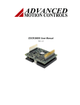
Step 4: Tuning
Position the Scope, Waveform Generator, and Velocity Loop windows such that a
majority of all the windows are visible as shown. The best method is to place the
oscilloscope in the lower left corner, while placing the current loop and Waveform
Generator windows in the upper and lower right corners as shown below.
44
•
•
•
Enable the drive by clicking the Enable/Disable Drive icon
The feedback filter cutoff frequency is used to dampen oscillations and noise in
the velocity measurements. During the next steps, if the motor exhibits excess
noise, bring the feedback cutoff frequency down to about 1000Hz or less. It is
usually ok to start with this value also.
Proper Velocity loop tuning starts with zero integral gain while increasing the
proportional gain until a 'knee' is formed (with no overshoot) in the Velocity
Measured trace as shown below. There may or may not be an error between the
Target and Measured traces, the key is to have a smooth knee shape.
45
•
At this point the Proportional gain is left alone and the Integral gain is increased
slowly until the 'knee' begins to deform as shown below. It is ok if the waveform
does not start to distort until the integral gain is very high. When the distortion
occurs, back off the Integral gain until the knee becomes smooth again.
•
Most systems will be tuned properly at this point. If your system is has unusual
characteristics, it may be necessary to adjust the derivative gain. If you cannot
achieve a desired velocity loop performance at this point, contact the AMC
technical support group at http://www.a-m-c.com .
46
•
•
•
Select the 'Not Connected' option in the waveform generator. If the motor starts to
make audible vibrations, increase the Low Speed Gain until the vibration and
noise stops.
Disable the drive by clicking the Enable/Disable Drive icon
.
On the Menu Bar, select Communication --> Store (or click the Store Settings
), then OK to store parameters to the drive nonvolatile memory.
icon
47
Position Loop Tuning
Position loop tuning is dependant on the mechanical load, and therefore will change with
any mechanical system changes. Position loop tuning should be performed with the
motor installed in the system. The position loop can be closed around velocity or torque
mode (depending on whether the velocity is enabled or disabled). If it is closed around
velocity mode, the position loop algorithm output becomes the new velocity set point. If
it is closed around torque mode, the position loop algorithm output becomes the new
torque set point. There are some important differences in the tuning process and
application of these two approaches:
Position around Velocity: This mode is most common in "contouring" application,
where a position trajectory must be tracked very closely. The velocity loop provides
additional "stiffness", and keeps the dynamic position errors minimal, since the system
now reacts to not just position errors, but also velocity errors (which can be interpreted as
position error changes). It is important to start with a stable yet responsive velocity loop.
Typically, it is sufficient to just use the position loop proportional gain. Feedforward gain
can be added to improve tracking performance (i.e. minimize the difference between
commanded and actual position). It is best to use a small step command as a reference
signal during tuning.
Position around Torque: This mode is most common in point-to-point applications,
where actual motion between start and end point is not very critical. In this case, velocity
loop tuning can be avoided. This can be advantageous if the velocity feedback is poor
(e.g. low resolution encoder, poor encoder quadrature...). In this case, the tuning process
requires that the position loop proportional and derivative gain are increased
simultaneously, unless the system has sufficient friction, in which case no derivative gain
is necessary. Once a stable response is achieved, integral gain can be added to improve
stiffness. It is best to use a triangular waveform or a step command with the profiler
enabled as a reference signal during tuning.
48
Step 1: Position Loop Window Set Up
1. Verify the drive is disabled
2. From the Main Block Diagram, open the Position Loop window.
3. Set the Proportional, Integral, Derivative, Velocity Feedforward, and
Acceleration Feedforward gains to zero.
4. Select the check box for Position Loop Enabled.
Step 2: Zero the Measured and Target Position
It is necessary to zero the target and measured position so that they are equal to each
other, and the motor does not run away when the bridge is enabled. Before continuing
with this step, click on the Config block in the Main Block Diagram and select the
position limits tab. Verify the value of Measured Position is set to zero.
49
1. From the Main Block Diagram, click I/O Configuration and select the Digital
Inputs tab.
2. Set the Measured Position to zero by checking Load Measured Position under and
assigned input. Set the Target Position to zero by checking Load Target under an
assigned input. Click the apply button.
3. Clear the check boxes checked in 2. and once again click Apply.
4. Click OK to close the I/O Configuration window.
50
Step 3: Waveform Generator Set Up
In the Position Loop window, click the Waveform Generator button (or select Tools -->
Waveform Generator on the menu bar) to open the Waveform Generator screen. Set up
the Waveform Generator as follows.
1. Select the Square Waveform Type.
2. Set Frequency to around 2-3 Hz. The Frequency should be slow enough to allow
the motor to settle in position.
3. Ensure Offset is zero.
4. Ensure Symmetry is 50%.
5. Select Waveform Into The Position Loop.
6. Set the waveform amplitude between 1//8 and 1/2 revolution for a rotary motor.
51
Step 4: Oscilloscope Set Up
1. On the menu bar, select Tools --> Oscilloscope (or click the oscilloscope icon on
the toolbar
) to open the digital oscilloscope. Set up the scope view as follows.
2. Use the drop down menu to change the channel 1 signal to Motor Position Target.
3. Use the drop down menu to change the channel 2 signal to Motor Position
Measured.
4. Change the Trigger Source to Motor Position Target with the Level set to zero.
5. Ensure Trigger Mode is Normal.
6. Change Time/Div to 20-50 msec.
52
Step 5: Tuning
1. Position the Scope, Waveform Generator, and Current Loop windows such that a
majority of all the windows is visible.
2. Enable the drive by clicking the Enable/Disable Drive icon
3. Use the Proportional Gain, Integral Gain, and Derivative Gain sliders or arrow
buttons to adjust the Motor Position Measured waveform on the oscilloscope and
match the Motor Position Target as closely as possible without excessive
overshoot. It is not necessary to adjust the Velocity or Acceleration Feedforward
Gains.
4. Readjust the Gains as Necessary.
5. Disable the drive by clicking the Enable/Disable Drive icon
.
6. When position loop gain adjustments are complete, click Not Connected on the
Waveform Generator to remove the command signal from the drive.
7. On the Menu Bar, select Communication --> Store (or click the Store Settings
icon ), then OK to store parameters to the drive nonvolatile memory.
53
Command Input and Scaling
Once the drive's commutation parameters, limits, and tuning values are configured, it is
ready to have I/O configured for machine control. General I/O is provided for use with
limit switches, temperature sensors, brakes, and other safety devices. See the hardware
manual for your specific drive to determine how to interface with the drive's I/O. The last
step to commissioning the drive is setting and scaling the Command Source. Use the
following links to perform final I/O and Command source configuration.
1. Command Source
2. I/O Configuration
54
Command Source
The Command Source window can be opened by clicking on the command source
block in the main block diagram. It allows selection and configuration of the
command source. The following command sources are available (depending on
operating mode):
•
Analog Input
Selects an analog input as the command source for the drive. Configuration of this
input can be done in the I/O Configuration window. The
button displays
analog input assignments as shown below. All analog inputs are shown. If more
than one is available, you may select it from the Select an input box. You may not
select an input shown in the Assigned input(s) box because it is assigned to
another task.
55
•
Step And Direction
Selects the step and direction inputs (see hardware manual or data sheet) to
control the motor in a simulated stepper motor configuration. Click on the
button to show the Step & Direction Input Ratio window as described below.
Input Counts are the number of input pulses desired to move the motor by a given
number of counts. Position Counts is the number of counts desired to move for
the given input counts. If using an encoder, Position Counts represents the
number of encoder counts. If using a resolver drive, Position Counts represents
the number of resolver counts as determined by the specified resolver resolution.
The number entered in either field must be between 1 and 65535.
The Load Target Command specifies what occurs when you activate a Load
Target command via a digital input. You may choose the drive to load a specified
count into the position target, or you may choose the drive to set the target
position equal to the currently measured position. Be aware that the first option
may cause the motor to jump to the specified target position when activated.
•
Interface Input
Selects the communication interface as the command source for the drive. This
means that a new command value is set via the interface. The
button displays
the commanded input assignments and allows you to select a specific commanded
input.
56
•
Encoder Following
Selects the secondary encoder input (see hardware manual or data sheet) to drive
the motor in a master/slave configuration. Click on the
button to bring up the
window shown below.
Input Counts are the number of quadrature input pulses desired to move the motor
by a given number of counts. Position Counts is the number of counts desired to
move for the given input counts. If using an encoder for primary feedback,
Position Counts represents the number of encoder counts to move. If using a
resolver for primary feedback, Position Counts represents the number of resolver
counts as determined by the specified resolver resolution.
The Invert Polarity checkbox changes the resulting motor direction for a given
input command.
The Load Target Command specifies what occurs when you activate a Load
Target command via a digital input. You may choose the drive to load a specified
count into the position target, or you may choose the drive to set the target
position equal to the currently measured position. Be aware that the first option
may cause the motor to jump to the new target position when activated.
•
PVT
Selects PVT as the control mode. Click the
shown below.
button to bring up the window
57
The PVT input method widow allows you to select between Absolute and
incremental PVT points. It also allows you to define the buffer level at which a
buffer threshold warning will occur.
•
No Command
This assigns no command source to the drive. Typically, No Command will be
automatically assigned when major control loop changes are performed. This is a
protection feature to minimize sudden motor movement.
•
Comm. Channel
The command will automatically be assigned when the drive is being controlled
by an outside source. This capability is currently only available with our
CANopen products.
58
I/O Configuration
The I/O Configuration window allows configuration and diagnostics of all digital and
analog programmable inputs and outputs. This window can be accessed by clicking on
the I/O icon on the main screen.
Analog Inputs:
•
Each programmable analog input can be assigned a certain drive function.
Assignment of these functions can be made in the Command Source or Feedback
59
•
•
window. Each input can also be scaled, according to the selected function, to
provide an optimal range. Entering the numerical value of the chosen function for
a 1V input signal performs the scaling. An offset (in Volts) can also be defined.
Note: selections become effective, after clicking the Apply or OK button.
Check the drive data sheet to find the number of available analog inputs.
Analog Outputs:
•
•
•
•
•
•
Each programmable analog output can be assigned to a certain drive variable.
Each output can also be scaled, according to the selected variable, to provide an
optimal range. Entering the numerical value of the chosen variable for a 1V
output signal performs the scaling.
An offset (in Volts) can also be defined.
Note: selections become effective, after clicking the Apply or OK button.
Check the drive data sheet to find the number of available analog outputs.
A list of available outputs signals and their definitions can be found in the Signal
Definitions page.
60
Digital Inputs:
•
•
The present status of each input is displayed (gray= Not Active, green= Active).
The Active Low checkmark determines the input polarity. Active low means the
input must be pulled-down for the input to be considered ON.
Each input can be assigned to one or more functions via the checkmark matrix. If
more then one function is assigned to a single input, the following priority rules
apply (from highest to lowest):
Inhibit
Dynamic brake
Positive or negative inhibit
Phase Detection
The Motor Over Temperature function depends on the selected function in the
Drive Control window.
61
•
Note: selections become effective, after clicking the Apply or OK button.
Digital Outputs:
•
•
The present status of each output is displayed (gray= Not Active, green=Active).
The Active High checkmark determines the output polarity. Active High means
the output is pulled-down if the output is considered OFF. Each output can be
assigned one or more functions via the checkmark matrix. If more then one
function is assigned to a single output, the functions are OR-ed, which means that
if one of the functions is true, the output will be turned ON.
Note: selections become effective, after clicking the Apply or OK button.
62
Appendix
63
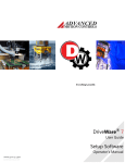
Digital Scope
The digital oscilloscope may be opened by going to Tools > Oscilloscope on the menu
on the toolbar. The oscilloscope provides real-time feedback
bar, or by clicking
during tuning and setup. This multi-channel digital scope behaves similarly to a
traditional oscilloscope but provides access to internal drive signals. You may have a
maximum of eight channels shown at any one time depending on the bandwidth used for
each channel. The units used in the vertical division setting depend on the selected signal.
Standard prefixes such as u (micro-), m (milli-), k (kilo-), M (mega-), etc. are used for
larger scaling factors. The bridge does not need to be enabled to use the scope. All that is
required is that the drive be powered up and connected. An explanation of how to use the
scope is described below.
Digital Scope Window
The digital scope is a powerful tool that comes in handy during tuning and diagnostics.
You can select from more than forty different signals to monitor while testing or
64
troubleshooting your machine. Detailed descriptions of scope components are described
below.
Channel Select
•
•
•
•
•
•
•
•
Channel select drop down menu: Allows you to select which channel you wish
to display.
Change: This opens a new window so you can use the selected channel to
display a signal of your choice.
Add Signal: Adds a new channel to the scope (if available) and allows you to
select a corresponding signal of your choice. This button will be disabled (grey) if
all oscilloscope channels are used.
Remove: Removes the selected channel from the scope.
Remove All: Removes all channels, resulting in no signals displayed.
Signal Scaling: Allows you to adjust the scale in units per division. The type of
units used changes depending on the signal chosen. The signal to be scaled
corresponds to the channel selected in the channel select drop down menu.
Offset: Adjusts the offset of the signal shown in the digital scope display. The
offset corresponds to the channel selected in the channel select drop down menu.
A list of available channels and their definitions can be found in the Signal
Definitions page.
Signal Window
•
•
•
Channel: Shows the color associated with the channel as seen in the digital scope
display
Signal: Shows the signal associated with the color and channel.
Units/Div: Shows the units per division for the corresponding signal as seen in
the digital scope display.
65
•
Offset: Shows the offset associated with the signal as seen in the digital scope
display
Trigger Settings
•
•
•
•
•
•
Source: Displays the currently selected signal to be used as a trigger.
Change: Allows you to change the trigger source.
Level: Allows you to select the level at which you want the scope to trigger.
Slope: Sets the trigger slope to positive slope or negative slope.
Mode: Sets the trigger mode to one of the following: Normal Mode: The scope
triggers according to the settings specified. Single: The scope triggers once,
according to the settings specified, after Run/Stop button is selected. Auto: The
scope triggers automatically, ignoring the settings specified.
Horizontal Location: Allows you to adjust the horizontal (time-based) level at
which the scope triggers.
Time and Mode Settings
•
•
•
Time/Div: Sets the horizontal scaling as seen on the scope in units of time per
division
Mode: Sets the mode in which the scope captures data. Normal mode refreshes
the screen in intervals dependant on the time per division selected. A longer time
period selected will take longer to update the scope. Roll mode captures data and
refreshes the screen in a continuous roll. Note: you will be limited to 200
msec/Div minimum while in roll mode.
Measure:
1. Time: This allows you measure time differences between any two point on the
scope display. Click the Time checkbox to display two vertical lines on the scope
plot. The difference in time between the two lines is displayed in the box to the
right of the check box. Left click to drag each line or right click to drag both.
66
2. Signal Level: Select a channel for measurement from one of the two dropdown
boxes. You may use either of the two dropdown menus to select a channel. The
vertical difference between the horizontal lines is displayed next to the channel
selection dropdown; the selected channels units apply. Left click to drag each line
or right click to drag both.
67
Waveform Generator
The Waveform Generator is used to generate an internal signal during drive tuning and
other procedures. With this waveform generator, the need for external signal sources
during tuning is eliminated. The Units select option allows you to choose between using
load units or motor units as defined in the User Units window. To open the waveform
generator, go to Tools > Waveform generator on the menu bar.
68
Waveform
Type:
Select a DC (constant), square wave, triangle wave, or sinusoidal
waveform. The sinusoidal waveform option is not available when
waveform generator is connected to the position loop
Waveform Into
The:
Select the destination for the waveform signal. Not Connected means the
waveform signal will not be used. Command Profiler means the command
signal will be limited as defined in the
Command Profiler Window.
Units:
Selects whether the amplitude and offset will be defined in load units or
motor units. These units are configured in the User Units during the Drive
Parameter Configuration process.
Frequency:
Select the frequency of the waveform signal. This becomes
inactive when "DC" is selected for the waveform type.
Amplitude:
Corresponds to the amplitude of the waveform signal (equivalent to half of
the peak-to-peak value). Disabled in case a DC waveform is selected.
Offset:
Adds an offset to the selected waveform. If a DC waveform is selected, the
offset corresponds to the DC signal amplitude.
Symmetry
Corresponds to the duty cycle or symmetry of the waveform signal. This
becomes inactive when DC is selected for the waveform type.
69
Command Profiler
The Command profiler allows you to limit the change in input command signal as seen
by the drive. The resulting effect is dependant on the operating mode. This is a command
smoother, not a drive limiter. In other words, it will change how the command is seen by
the drive, but if an event occurs which is not affected by the command, the drive will
react according to drive limits. For changing drive limits, see Drive Configuration.
The Command Profiler window can be opened by clicking on its icon in the main block
diagram.
Current Loop Control
Limits the jerk, or change in commanded torque.
Velocity Loop Control
Limits the acceleration, or change in commanded velocity.
Position Loop Control
Limits the velocity, or change in commanded position.
The Command Profiler window changes depending on the mode of operation you are
using. See below for the three possible windows.
70
Current Loop Control
Velocity Loop Control
71
Position Loop Control
72
Signal Definitions
The following tables show all of the signals that can be measured using the Oscilloscope
and Multimeter. These signals may also be used as analog outputs in compatible drives.
Note : Depending on the drive type, motor type, and motor settings, some of the signals
may not be available.
Current Measurements
Value
Definition
Iq - Target
This is the commanded current ignoring current limit
settings.
Iq - Demand
The commanded current, after current limits have been
applied. This value is zero when the drive is inhibited.
Iq - Measured
The actual measured current being delivered to the motor.
Ideally, this value should be as close as possible to the
demand current.
Id - Target
This represents the flux producing stator current in an AC
induction motor. Id should equal zero when using a
permanent magnet motor.
Id - Demand
This represents the flux producing stator current in an AC
induction motor. Id should equal zero when using a
permanent magnet motor.
Current Phase A
The measured current in motor phase A. The sum of all
three phases should add up to zero.
Current Phase B
The measured current in motor phase B. The sum of all
three phases should add up to zero.
Flux Ref. Current Target
The commanded flux reference current ignoring limits.
The flux reference current is the current induced in the
rotor of an AC induction motor.
Flux Ref. Current Demand
The commanded flux reference current, after limits have
been applied. The flux reference current is the current
induced in the rotor of an AC induction motor.
73
Flux Ref. Current Measured
The measured flux reference current. The flux reference
current is the current induced in the rotor of an AC
induction motor.
Flux Ref. Current Error
The difference between the flux reference current target
and the flux reference current measured.
Velocity Measurements
Value
Definition
Motor Velocity Target
This is the commanded velocity ignoring velocity limit
settings.
Motor Velocity Demand
The commanded velocity, after velocity limits have been
applied. This value is zero when the drive is inhibited.
Velocity Feedback
The velocity as measured by the velocity feedback device
(before filtering)
Motor Velocity Measured
The velocity as measured by the velocity feedback device
(after filtering)
Velocity Error
The difference between the motor's target velocity and
measured velocity.
Load Velocity Measured
This is equal to the velocity measured, but displayed in
load units.
Position Measurements
Value
Definition
Motor Position Measured
The position as measured by the position feedback device.
Motor Position Target
This is the commanded position ignoring position limit
settings.
Motor Position Demand
The commanded position, after position limits have been
applied.
Position Error
The differenece between the motor's target position and
measured position.
Load Position Measured
This is equal to the position measured, but displayed in
load units.
Auxilliary Input
The position value measured from the drives auxilliary
74
inputs.
Commutation
Value
Definition
Sync Error
The error between the actual number of encoder counts
compared to the expected number of encoder counts as
entered in the Motor page. Values will vary depending on
Hall or Index synchronization.
Hall State
The decimal equivalent of the binary combination of the
three hall states where Hall A is bit 1 and Hall C is bit 3.
(5V = 1, 0V = 0)
Phase Angle
The present number of degrees of the rotor inside one
electrical cycle. Also may be called Electrical Angle.
Sync. Capture
The encoder count captured at the Synchronization edge.
This will vary depending on the Sync edge chosen from
autocommutation (Hall or Index edge).
Stator Angle
The present number of degrees of the stator inside one
electrical cycle. This value is equal to the phase angle plus
the slip angle.
Voltage
Value
Definition
Analog Output 1
The present voltage applied to analog output 1.
Analog Output 2
The present voltage applied to analog output 2.
DC Bus Voltage
The present voltage applied to the high voltage input of
the drive.
Voltage Phase A
The voltage, with respect to DC bus ground, applied to
motor phase A
Voltage Phase B
The voltage, with respect to DC bus ground, applied to
motor phase B.
Voltage Phase C
The voltage, with respect to DC bus ground, applied to
motor phase C.
Analog Input 1
The voltage, with respect to signal ground, applied to
analog input 1.
Analog Input 2
The voltage, with respect to signal ground, applied to
analog input 2.
75
Analog Input 3
The voltage, with respect to signal ground, applied to
analog input 3.
Command Profiler
Value
Command Profiler Input
Definition
The commanded signal input to the Command Profiler.
When the Command Profiler is enabled, all commands
pass through it first for profiling.
Temperatures
Value
Definition
Motor Temp.
The present temperature of the motor read and scaled
from the appropriate analog inputs.
Drive Temperature
Depending on the specific drive, an analog temperature
sensor may be present to report the actual drive
temperature.
Torque
Value
Definition
Load Torque Measured
The torque applied at the load. This value is calculated
from measured current, as delivered to the motor from the
drive, and other user supplied parameters in the Motor
Data and User Units windows.
Motor Torque Measured
The torque applied by the motor. This value is calculated
from measured current, as delivered to the motor from the
drive, and other user supplied parameters in the Motor
Data window.
76
Drive
Value
Definition
Drive Position
The drive position as measured by the primary feedback
device. No position is measured when Hall sensors are
used as the only primary feedback device. Always
measured in units of counts.
Drive Velocity
The drive velocity as measured by the primary feedback
device. No velocity is measured when Hall sensors are
used as the only primary feedback device. Always
measured in units of counts.
Commanded Input Value
Value
Definition
Commanded Input Eight
The decimal value read from interface input 8.
Commanded Input Seven
The decimal value read from interface input 7.
Commanded Input Six
The decimal value read from interface input 6.
Commanded Input Five
The decimal value read from interface input 5.
Commanded Input Four
The decimal value read from interface input 4.
Commanded Input Three
The decimal value read from interface input 3.
Commanded Input Two
The decimal value read from interface input 2.
Commanded Input One
The decimal value read from interface input 1.
77
Drive Status
The Drive Status window shows the drive status in three categories:
Drive Protection Status: these are internal drive faults and states
Event
Description
Drive Reset
Indicates that the drive powered up in a disabled state. This occurs each time
the drive is reset.
Drive Internal
Error
Checksum error of the drive run-time firmware.
Short Circuit
Short circuit detected on the output power stage.
Current Overshoot
The actual output current exceeds the peak current capability of the power
output stage. Typically caused by overshoot in the current loop
Under Voltage
(HW)
The actual bus voltage is below the minimum allowed bus voltage
Over Voltage
(HW)
The actual bus voltage is above the maximum allowed bus voltage
Drive Over
Temperature
The internal drive temperature has reached the maximum allowed temperature
78
System Protection Status: system related errors that are detected by the drive.
Event
Description
Parameter
Restore Error
Checksum error during parameter loading from non-volatile memory.
Parameter Store
Error
Checksum error during parameter loading to non-volatile memory.
Invalid Hall
State
Invalid state of the Hall sensor inputs
Phase Sync.
Error
Improper commutation synchronization. Phase synchronization occurs with
sinusoidally commutated motors either during encoder index (default) or hall
edge. If an incorrect number of encoder counts is measured between
synchronization edges, a Phase Sync. Error will occur.
Motor Over
Temperature
Effective only if the motor temperature sensor is connected to an input on the
drive and the Motor Over Temperature function is selected for that input
Phase Detection
Fault
Effective only if the commutation is based on an incremental encoder only
Feedback Sensor
Indicates a malfunction of the feedback sensor (e.g. encoder or resolver).
Error:
Motor Overspeed
The motor has exceeded the maximum specified speed
Upper Measured
The measured position has exceeded the maximum limit.
Position Limit:
Lower Measured
The measured position has exceeded the minimum limit
Position Limit:
79
Drive System Status: internal drive status (does not necessarily correspond to a drive
fault status, but could relate to a system error).
Event
Description
Log Entry Missed
An event was not properly stored in the history log
Commanded Inhibit:
Indicates a drive inhibit event via the communication interface.
User Inhibit:
Indicates a drive inhibit event via a digital input
Positive Limit:
Indicates a drive inhibit event in the positive direction
Negative Limit:
Indicates a drive inhibit event in the negative direction
Current Limiting
Indicates a current limiting event as a result of the current limit settings
Continuous Current
Indicates that the actual output current has been reduced to the
continuous current setting.
Current Loop Saturated
Indicates maximum PWM duty cycle as a result of saturation in the
current loop
User Under Voltage
Indicates that the actual bus voltage is below the user defined under
voltage limit.
User Over Voltage:
Indicates that the actual bus voltage is above the user defined over
voltage limit.
Homing Complete
Homing has finished.
Commanded Quick
Stop
Indicates a quick stop event via the communication interface.
User Quick Stop
Indicates a quick stop event via a digital input.
Position Following
Error
Indicates an excessive position error in the position loop
Upper Target Position
Limit
Indicates that the target position has reached the positive target position
limit
Lower Target Position
Limit
Indicates that the target position has reached the negative target position
limit.
Load Measured
Position
Indicates that the measured position is being loaded with the Measured
Position Substitute value
Homing Active
Homing is being performed.
Apply Brake
The brake output has been activated.
80
Event
Description
PVT Buffer Full
The PVT buffer cannot accept any more information.
PVT Buffer
Empty
The PVT buffer contains no more information
PVT Buffer
The PVT threshold has been reached as defined in the PVT Input Settings
Threshold Exceed window .
PVT Buffer
Failure
An error has occurred while retrieving PVT information from the buffer.
PVT Buffer
Empty Stop
The PVT buffer has run out before a valid PVT stop point was sent.
PVT Sequence
Number
PVT trajectory points were received out of order (can indicate a missing PVT
point or repeated point).
Comm Channel
Error
Used exclusively with CANopen drives. This event is triggered by failure to
recieve a node-guard message within the specified life time of the drive. See
CANopen manual for more information on Node Guarding and Life Guarding.
Non-Sinusoidal
Commutation
Indicates that the drive is no longer in sinusoidal commutation mode
Phase Detection
Indicates that the drive is performing phase detection
Commanded
Dynamic Brake
Indicates a dynamic brake event via the communication interface
User Dynamic
Brake:
Indicates a dynamic brake event via a digital input
Shunt Regulator
Indicates the shunt regulator circuit is active
Phase Detection
Complete:
Indicates the phase detect routine has finished
Zero Velocity
Indicates that the measured motor velocity is within the zero velocity window
81
Event
Description
At Command
Indicates that the measured motor velocity has reached the commanded velocity,
within the At Velocity window (in velocity mode) or that the measured position
has reached the target position, within the In Position window (in position
mode).
Velocity
Indicates an excessive velocity error in the velocity loop
Following Error
Positive Target
Velocity Limit
Indicates that the target velocity has reached the positive velocity limit.
Negative Target
Indicates that the target velocity has reached the negative velocity limit
Velocity Limit
Command
Profiler Active
Indicates that the command profiler is active (i.e. is applying the user entered
rate limits).
At Home
Position
Indicates that the measured position has reached the Home Position, within the
In Home Position Window
This window shows both the present state of each event and the history (indicating
whether the event has occurred since the last reset or since power-up). Individual events
can be selected for reset, or all events can be selected for reset. The actual resetting of an
event depends on the event settings for that particular event, according to the settings in
the Drive Control window. A reset will reset both the present state and history of the
event (presuming the cause of the event is no longer present).
If you select the Commanded Inhibit event for reset, this will NOT enable the drive. Only
the Enable/Disable Drive button in the toolbar can be used to change the Commanded
Inhibit state.
The Drive Status Window also has a Fault Log and a Fault Log Counter. The Fault Log
contains a list of the faults that occurred and a time stamp (in milliseconds). The Fault
Log Counter contains a list off all faults and events and the number of times they have
occurred.
82
Drive Control
The Drive Control window allows configuration of event handling in the drive. Events
can correspond to a fault, or a particular internal drive state. The events have several
programmable attributes:
83
•
•
Disabled: the event handling can be disabled.
Event Action: the action to be taken by the drive after the response time has
elapsed. The table below shows the possible actions to choose from. For safety
reasons some actions are not available with some events.
•
Response Time: the time delay between the actual occurrence of the event and
the event action.
•
Recovery Time: the time after which the selected event action will be removed
when the cause of the event is no longer present.
Time-out Window: the time, after the recovery time and subsequent removal of
the event action, during which the drive will NOT consider an occurrence of the
event as a new occurrence. The Event Action will still be applied in case an event
does occur within this window. However, that occurrence will not be counted as a
new occurrence with regard to the Maximum Recoveries attribute.
Maximum Recoveries: the maximum number of occurrences of the event prior
to a permanent event action.
Unlimited Recoveries: there is no limit to the number of occurrences of the event
•
•
•
84
Event Action Description
No Action
Event Action is disabled
Disable
No power is delivered to the motor. Motor is allowed to move freely.
Power Bridge
Disables the drive from outputting to the motor in the positive direction, while
Disable
allowing commanded motion in the negative direction. The result is dependent on
Positive
the mode of operation. This action is not recommended in vertical applications
Direction
because the load will be free to fall once the limit is activated. For vertical loads, we
recommend using 'Positive Stop'.
Disables the drive from outputting to the motor in the negative direction, while
Disable
allowing commanded motion in the positive direction. The result is dependent on the
Negative
mode of operation.
Direction
Dynamic
Motor leads are virtually shorted together internally. However, the bridge enables to
Brake
protect motor by regulating motor current.
If the drive is controlling velocity or position, the load decelerates according to the
deceleration limit specified in Drive Configuration. Commanded motion in the in the
Positive Stop
positive direction has no affect. Motor continues to servo with zero command in the
positive direction.
If the drive is controlling velocity or position, the load decelerates according to the
Negative
deceleration limit specified in Drive Configuration. Commanded motion in the in the
Stop
negative direction has no affect. Motor continues to servo with zero command in the
negative direction.
If the drive is controlling velocity or position, the load decelerates according to the
Stop
deceleration limit specified in Drive Configuration. Commanded motion has no
affect. Motor continues to servo with zero command.
Apply Brake
Brake output is turned on, then bridge is disabled. Delay is set in Drive
then Disable
Configuration.
Bridge
Apply Brake
Brake output is turned on, then dynamic brake is applied. Delay is set in Drive
then Dynamic
Configuration.
Brake
Note: some of the above mentioned attributes are not programmable for certain events.
Events are grouped in the following categories:
85
Drive Protection
Event
Description
Short Circuit
Short-circuit condition of the power output stage
Hard Under Voltage
DC bus voltage below the drive hardware under voltage limit.
Hard Over Voltage:
DC bus voltage above the drive hardware over voltage limit
Drive Over Temperature
Drive internal temperature exceeded the maximum drive temperature
limit
Parameter Restore
Error:
An error during parameter download from non-volatile memory
Parameter Store Error
An error during parameter upload to non-volatile memory
Communication Error
Error during communication between drive and PC.
Voltage & Temperature:
Event
Description
Motor Over
Temperature
Applicable only when a motor temperature sensor is connected to a
programmable input (analog or digital) with the Motor Over Temperature
function. The event corresponds to this input becoming active.
User Under
Voltage
DC bus voltage below the User Under Voltage Limit setting (see Drive
Configuration).
User Over
Voltage
DC bus voltage above the User Over Voltage Limit setting (see Drive
Configuration).
Shunt Regulator
DC bus voltage above the Shunt Turn-on Voltage setting (see Drive
Configuration). Effective only on drive models with built-in shunt regulator.
86
Bridge Control
Event
Description
Commanded Inhibit
An inhibit command over the communications interface (active when
the stop light icon is red).
User Inhibit:
An inhibit command from a digital input.
Positive Limit:
A positive inhibit command from the communications interface or a
digital input.
Negative Limit
A negative inhibit command from the communications interface or a
digital input.
Commanded Dynamic
Brake:
A dynamic brake command over the communications interface.
User Dynamic Brake
A dynamic brake command from a digital input.
Commanded Quick Stop A quick stop event via the communication interface
User Quick Stop
A quick stop event via a digital input.
Current Control Events
Event
Description
Current Limiting
The drive is commencing current limiting (based on the current limit
settings).
Continuous Current
The drive has reached the continuous current setting, after current
limiting.
Current Loop
Saturated
The maximum PWM duty cycle has been reached due to current loop
saturation.
Current Overshoot
The drive output current has exceeded the maximum drive rating.
87
Commutation Control
Event
Description
Non-sinusoidal
Commutation
The drive is not commutating sinusoidally. This event occurs automatically
upon power-up before the motor has moved around. Otherwise, this may be
due to loss of synchronization or saturation, or the drive may be set for
trapezoidal commutation.
Phase Detection
The drive is going into phase detection mode (phasing based on the encoder
only feedback).
Invalid Hall State
An invalid state of the hall sensors has been detected.
Phase
Synchronization
Error
A synchronization loss due to a missing Hall sensor or encoder index edge
has occurred.
Feedback Sensor
Error
A feedback sensor error (e.g. missing encoder, bad resolver, etc.) has
occurred.
Phase Detection
Failure
The phase detection algorithm did not properly complete.
Phase Detection
Complete
The phase detection algorithm is complete.
Velocity Events
Event
Description
Motor Over Speed
The measured motor velocity has exceeded the motor over speed limit.
Zero Velocity
The measured motor velocity is within the Zero Velocity window.
Velocity Following
Error
The velocity following error exceeds the Velocity Following Error
window.
Positive Velocity Limit: The demand velocity has reached the Positive Velocity limit.
Negative Velocity Limit The demand velocity has reached the Negative Velocity limit
88
Command Events
Event
Description
Command Profiler The
Active
Command Profiler is affecting the target signal (i.e. rate limiting).
At Command
The measured motor velocity has reached the target velocity, within the At
Velocity Window (found in Drive Configuration ).
Load Target
The target value has been replaced with the predefined target position.
PVT Buffer Full
The PVT buffer cannot accept any more information.
PVT Buffer
Empty
The PVT buffer contains no more information
PVT Buffer
Threshold
The PVT threshold has been reached as defined in the PVT command type
window.
PVT Buffer
Failure
An error has occurred while retrieving PVT information from the buffer.
PVT Buffer
Empty Stop
The PVT buffer has run out before a valid PVT stop point was sent.
PVT Sequence
Number
PVT trajectory points were received out of order (can indicate a missing PVT
point or repeated point).
89
Position Events
Event
Description
Max Measured
Position:
The measured position has exceeded the Max Measured Position limit.
Min Measured
Position
The measured position has exceeding the Min Measured Position limit.
At Home Position
The measured position has reached the Home Position value, within the In
Home Position Window.
Position Following
Error
The position following error has exceeded the Position Following Error
limit.
Max Target Position The demand position has reached the Max Target Position limit.
Min Target Position The demand position has reached the Min Target Position limit.
Load Measured
Position
The measured position value has been replaced with the Measured Position
Substitute value.
Homing active
Homing is being performed.
Homing complete
Homing has finished.
Communication
Event
Description
Communication
Error
Used exclusively with CANopen drives. This event is triggered by failure to
recieve a node-guard message within the specified life time of the drive. See
CANopen manual for more information on Node Guarding and Life Guarding.
90