1
User Manual
May 2012
ZEESC312K Rev. C
Trademark Acknowledgments
ETHOS and Snap-on are trademarks of Snap-on Incorporated.
All other marks are trademarks or registered trademarks of their respective holders.
Copyright Information
©2012 Snap-on Incorporated.
All rights reserved.
Patents
US B1 5, 442,170; AU 690,261; US 6,693, 367 B1 Patents Pending.
Disclaimer
The information, specifications and illustrations in this manual are based on the latest information available at
the time of printing.
Snap-on reserves the right to make changes at any time without notice.
Visit our Web site at:
http://diagnostics.snapon.com (North America)
www1.snapon.com/diagnostics/uk (United Kingdom)
FOR TECHNICAL ASSISTANCE
CALL 1-800-424-7226 (North America)
CALL +44 (0) 845 601 4736 (United Kingdom)
E-mail [email protected] (United Kingdom)
For technical assistance in all other markets, contact your selling agent.
ii
EC-DECLARATION OF CONFORMITY
We,
Snap-on Diagnostics
a division of Snap-on UK Holdings Ltd.
Denney Road, King's Lynn
Norfolk, PE30 4HG
England
declare under our sole responsibility for design and manufacture that the following product,
to which this declaration relates, is in conformity with the following European Directives:
Conforms to:
IEC 60950-1 (2001) First Edition
Product:
ETHOS
Model:
EESC312 / EESC112
Applied European standards:
EN 61326-1:1997 + A1:1998 + A2:2001 + A3:2003
EN6100-3-2:2000
EN6100-3-3:1995 + A1:2001
King's Lynn 28-03-2007
Name
: A. Barker
Position
: Director European Supply Chain
Signature
:
Document number: ce-decl-sod-ethos
iii
Safety Information
For your own safety and the safety of others, and to prevent damage to the equipment and
vehicles upon which it is used, it is important that the accompanying Safety Information be
read and understood by all persons operating, or coming into contact with, the equipment. We
suggest you store a copy near the unit in sight of the operator
This product is intended for use by properly trained and skilled professional automotive
technicians. The safety messages presented throughout this manual are reminders to the
operator to exercise extreme care when using this test instrument.
There are many variations in procedures, techniques, tools, and parts for servicing vehicles,
as well as in the skill of the individual doing the work. Because of the vast number of test
applications and variations in the products that can be tested with this instrument, we cannot
possibly anticipate or provide advice or safety messages to cover every situation. It is the
automotive technician’s responsibility to be knowledgeable of the system being tested. It is
essential to use proper service methods and test procedures. It is important to perform tests
in an appropriate and acceptable manner that does not endanger your safety, the safety of
others in the work area, the equipment being used, or the vehicle being tested.
It is assumed that the operator has a thorough understanding of vehicle systems before using
this product. Understanding of these system principles and operating theories is necessary for
competent, safe and accurate use of this instrument.
Before using the equipment, always refer to and follow the safety messages and applicable
test procedures provided by the manufacturer of the vehicle or equipment being tested. Use
the equipment only as described in this manual.
Read, understand and follow all safety messages and instructions in this manual, the
accompanying safety manual, and on the test equipment.
Safety Message Conventions
Safety messages are provided to help prevent personal injury and equipment damage. All
safety messages are introduced by a signal word indicating the hazard level.
! DANGER
Indicates an imminently hazardous situation which, if not avoided, will result in death or
serious injury to the operator or to bystanders.
! WARNING
Indicates a potentially hazardous situation which, if not avoided, could result in death or
serious injury to the operator or to bystanders.
! CAUTION
Indicates a potentially hazardous situation which, if not avoided, may result in moderate or
minor injury to the operator or to bystanders.
iv
Safety Information
Important Safety Instructions
Safety messages contain three different type styles.
• Normal type states the hazard.
• Bold type states how to avoid the hazard.
• Italic type states the possible consequences of not avoiding the hazard.
An icon, when present, gives a graphical description of the potential hazard.
Example:
! WARNING
Risk of unexpected vehicle movement.
• Block drive wheels before performing a test with engine running.
A moving vehicle can cause injury.
Important Safety Instructions
For a complete list of safety messages, refer to the accompanying safety manual.
SAVE THESE INSTRUCTIONS
v
Contents
Safety Information ...............................................................................................................iv
Contents ...............................................................................................................................vi
Chapter 1: Using This Manual ............................................................................................. 1
Conventions............................................................................................................................ 1
Bold Text .......................................................................................................................... 1
Symbols ........................................................................................................................... 1
Terminology ..................................................................................................................... 1
Notes and Important Messages ....................................................................................... 2
Procedures....................................................................................................................... 2
Additional Manuals ................................................................................................................. 2
Chapter 2: Introduction........................................................................................................ 3
Functional Description ............................................................................................................ 3
Technical Specifications ......................................................................................................... 5
Control Buttons....................................................................................................................... 6
S Button ........................................................................................................................... 6
N/x (Back) Button .............................................................................................................7
Y/a (Accept) Button ......................................................................................................... 7
Directional Buttons ........................................................................................................... 7
Power Button ...................................................................................................................7
Connections............................................................................................................................ 7
DC Power Input................................................................................................................ 8
USB Port .......................................................................................................................... 8
Mini USB Port ..................................................................................................................8
Data Cable Connector ..................................................................................................... 8
CompactFlash Card Slot .................................................................................................. 8
Power Supply ......................................................................................................................... 8
Vehicle Power ..................................................................................................................9
Battery Power ..................................................................................................................9
AC/DC Power Supply....................................................................................................... 9
93L Data Cable..................................................................................................................... 10
Chapter 3: Getting Started................................................................................................. 11
Supplying Power................................................................................................................... 11
Installing the Batteries .......................................................................................................... 11
Connecting to Vehicle Power ............................................................................................... 12
Connecting the AC/DC Power Supply .................................................................................. 14
Powering On the Unit ...........................................................................................................14
Selecting a Language...........................................................................................................14
Powering Off the Unit ...........................................................................................................15
Demonstration Programs...................................................................................................... 15
Chapter 4: Navigation ........................................................................................................ 16
Screen Layout ...................................................................................................................... 16
vi
Contents
Title Bar.......................................................................................................................... 16
Toolbar ........................................................................................................................... 17
Main Body ......................................................................................................................18
Making Selections ................................................................................................................ 18
Screen Messages................................................................................................................. 19
Loading and Connecting Messages............................................................................... 19
Confirmation Messages ................................................................................................. 19
Warning Messages ........................................................................................................ 19
Error Messages.............................................................................................................. 19
Chapter 5: Operations........................................................................................................ 20
Selecting from the Main Menu..............................................................................................21
Identifying the Vehicle .......................................................................................................... 21
Main Menu Identification Options................................................................................... 22
Selecting a System............................................................................................................... 23
Connecting to a Vehicle........................................................................................................24
Selecting from the Vehicle Menu.......................................................................................... 25
Codes Menu................................................................................................................... 25
Data Display...................................................................................................................26
Generic Functions .......................................................................................................... 32
Using Tools........................................................................................................................... 33
S Button ......................................................................................................................... 33
Units ............................................................................................................................... 34
Setup.............................................................................................................................. 34
Sys (System Information)............................................................................................... 35
Connect-to-PC ............................................................................................................... 35
Backup to CF ................................................................................................................. 36
Update from CF ............................................................................................................. 36
Recording and Viewing Movies ............................................................................................ 36
Service Menu........................................................................................................................ 36
Chapter 6: Maintenance ..................................................................................................... 38
Cleaning and Damage Inspection ........................................................................................ 38
Display Window Replacement..............................................................................................38
Replacing the Batteries ........................................................................................................39
Disposing of the Batteries ..............................................................................................40
Storage Tips ......................................................................................................................... 40
Making a Backup CompactFlash (CF) Card......................................................................... 41
Restoring from a CompactFlash (CF) Card.......................................................................... 41
Updating from a CompactFlash (CF) Card........................................................................... 42
Appendix A: Troubleshooting ........................................................................................... 43
Bent Cable Connector Pin .................................................................................................... 43
Erratic or No Communication ............................................................................................... 43
No Communication Message ............................................................................................... 43
Cannot Access the CompactFlash® (CF) Card.................................................................... 44
Unit Will Not Power On.........................................................................................................44
Unit Will Not Power Off......................................................................................................... 44
Restarting the Unit................................................................................................................ 44
Appendix B: Downloading and Installing Software Updates ......................................... 45
vii
Contents
Check for Service Upgrades Before Use.............................................................................. 45
Verifying Minimum PC Requirements................................................................................... 45
Verifying PC System Properties..................................................................................... 46
Downloading and Installing ShopStream Connect ............................................................... 46
Downloading Service Upgrades ........................................................................................... 49
Before You Begin ...........................................................................................................49
Installing a Service Upgrade .......................................................................................... 49
Index .................................................................................................................................... 52
viii
Chapter 1
Using This Manual
This manual contains tool usage instructions. Some of the illustrations shown in this manual
may contain modules and optional equipment that are not included on your system.
1.1 Conventions
The following conventions are used.
1.1.1 Bold Text
Bold type is used in procedures to accent selectable items such as buttons and menu options.
Example:
• Press the Y/a button.
1.1.2 Symbols
Different types of arrows are used.
The “greater than” arrow (>) indicates an abbreviated set of selection instructions.
Example:
• Select Utilities > Tool Setup > Date.
The previous statement abbreviates the following procedure:
1. Navigate to the Utilities button.
2. Use the directional keys to navigate to and highlight the Tool Setup submenu.
3. Use the directional keys to navigate to and highlight the Date option from the submenu.
4. Press Y/a to confirm the selection.
1.1.3 Terminology
The term “select” means highlighting a button or menu item using the directional keys and
pressing the Y/a button to confirm the selection.
Example:
• Select Reset.
The above statement abbreviates the following procedure:
1
Using This Manual
Additional Manuals
1. Navigate to and highlight the Reset button.
2. Press the Y/a button.
1.1.4 Notes and Important Messages
The following messages are used.
Notes
A NOTE provides helpful information such as additional explanations, tips, and comments.
Example:
i
NOTE:
For additional information refer to...
Important
IMPORTANT indicates a situation which, if not avoided, may result in damage to the test
equipment or vehicle.
Example:
IMPORTANT:
Do not force the CompactFlash® card into the slot.
1.1.5 Procedures
An arrow icon indicates a procedure.
Example:
z
To change screen views:
1. Select the View button.
The drop-down menu displays.
2. Select an option from the menu.
The screen layout changes to the format you selected.
1.2 Additional Manuals
The scan tool hardware works in conjunction with Vehicle Communication Software (VCS),
each version of VCS has its own manual. See the appropriate manual for information
regarding these products.
2
Chapter 2
Introduction
The ETHOS® (Figure 2-1) scan tool uses Vehicle Communication Software to provide
vehicle-specific diagnostic trouble codes (DTCs) and datastream information for various
vehicle control systems such as engine, transmission, antilock brake system (ABS) and more.
Your scan tool can also graph live data parameters, record data, clear diagnostic trouble
codes (DTCs) from the vehicle electronic control module (ECM) memory, and reset the
vehicle malfunction indicator lamp (MIL).
Contact your sales representative for availability of software add-ons and upgrades.
Figure 2-1 ETHOS scan tool
2.1 Functional Description
This section illustrates external features, ports and connectors of the ETHOS unit.
3
Introduction
Functional Description
2
1
9
8
4
3
6
7
Figure 2-2 ETHOS unit front view
1— Y/a (accept) button
2— S button
3— b (Up) button
4— N/x (back) button
5— CompactFlash® card slot, under endgrip
6— c (Right) button
7— Power button
8— d (Down) button
9— e (Left) button
1
2
3
Figure 2-3 ETHOS unit top view
1— DC power supply input
2— Data cable connector
3— USB port
4— Mini USB port
4
5
4
Introduction
Technical Specifications
1
2
Figure 2-4 ETHOS unit back view
1— Battery cover
2— Locking tabs
2.2 Technical Specifications
Display:
Light Emitting Diode (LED) backlight monochrome screen
320 x 240 resolution
4.7 inch (119.38 mm) diagonal
Batteries:
(6) 1.5V AA
AC adapter:
Input: 100–240V, 47–63 Hz
Output: 15V DC
Dimensions:
Width:
9.05 inches
229.9 mm
Height:
5.70 inches
144.7 mm
Depth:
1.67 inches
42.3 mm
5
Introduction
Control Buttons
Weight:
Without batteries
1.42 lbs
643.5 g
Operating Temperature Range:
14 to 104°F
-10 to 40°C
Storage Temperature Range:
-4 to 149°F
-20 to 65°C
Data Buffer
240 data frames (values per parameter)
Communication Protocols
Your ETHOS scan tool supports the following OBD-II/EOBD communications protocols:
SAE J1850 (VPW)
SAE J1850 (PWM)
ISO 9141-2
ISO 14230-4 (KWP 2000)
ISO 15765-4 (CAN)
In addition, the optional vehicle communications software allows you to access “enhanced”
diagnostic information for specific vehicle manufacturers.
2.3 Control Buttons
The scan tool has the following control buttons (Figure 2-2 on page 4):
•
•
•
•
•
•
•
•
S (function)
N/x (back)
Y/a (accept)
b (Up)
d (Down)
e (Left)
c (Right)
Power
2.3.1 S Button
The S button can be customized to perform different functions. See “S Button” on page 33 for
additional information.
6
Introduction
Connections
2.3.2 N/x (Back) Button
The N/x button is used to do the following:
•
•
•
•
To exit a menu or program.
To close an open list and return to the previous menu.
To answer “No” when a Yes or No choice is given.
To return to the main menu.
2.3.3 Y/a (Accept) Button
The Y/a button is used to do the following:
• To select the item that you highlighted using the direction buttons.
• To answer “Yes” when a Yes or No choice is given.
2.3.4 Directional Buttons
The directional, or arrow, buttons move the cursor or highlight in their respective directions:
•
•
•
•
Up (b)
Down (d)
Left (e)
Right (c)
2.3.5 Power Button
The Power button powers up the tool, and turns it off. See “Powering On the Unit” on page 14
and “Powering Off the Unit” on page 15 for details.
2.4 Connections
This scan tool uses the following connections (Figure 2-3 on page 4):
•
•
•
•
•
DC power adapter input
USB port
Mini USB port
Data cable connector
CompactFlash (CF) card slot
7
Introduction
Power Supply
2.4.1 DC Power Input
The DC power input can be used to power the unit via an AC/DC power supply. For related
information, see the following sections:
• “AC/DC Power Supply” on page 9
• “Connecting the AC/DC Power Supply” on page 14
2.4.2 USB Port
This scan tool has a USB port for connecting to a printer.
2.4.3 Mini USB Port
The mini USB port on top of the unit is used for updating the internal software, and for
transferring saved files to a personal computer.
2.4.4 Data Cable Connector
The data cable connector is used to connect the scan tool to a vehicle data link connector
(DLC) for testing.
For related information, see the following sections:
• “93L Data Cable” on page 10
• “Connecting to Vehicle Power” on page 12
2.4.5 CompactFlash Card Slot
The CompactFlash (CF) card slot, located under the handgrip, adds optional functionality to
the scan tool. The ETHOS unit does not require a CF card to operate. The CF card slot on the
scan tool is used for creating a backup file of the operating system and for accessing certain
update functions.
2.5 Power Supply
This scan tool can receive power from three sources:
• Vehicle power
• Battery power
• AC/DC power supply
For related information, see “Vehicle Power” on page 9.
8
Introduction
Power Supply
2.5.1 Vehicle Power
Vehicle power is required for the scan tool to properly communicate with the vehicle during
testing. The 93L Data Cable (EAC0093L01A) provides 12V power to the unit through the
vehicle data link connector (DLC). The scan tool turns on automatically whenever it is
connected to a DLC that provides power.
Certain vehicles do not provide vehicle power on the DLC. For these applications, a separate
cable adapter and power cable are needed to power the unit. Optional data cable adapters are
available for a number of vehicle manufacturers. Contact your sales representative for
availability.
The power cable connects to a port on the cable adapter.
IMPORTANT:
Never connect the optional power cable or the AC/DC power supply to the DC power supply
input on top of the unit when the scan tool is communicating with the vehicle.
For related information, see “Connecting to Vehicle Power” on page 12.
2.5.2 Battery Power
This scan tool can receive power from six internal type AA batteries. Alkaline or rechargeable
nickel-metal hydride (NiMH) batteries must be used, Standard (lead/zinc) batteries do not
provide sufficient power and have a tendency to leak, which can damage the scan tool.
Battery power should not be the primary source of power. Vehicle power should be the source
of power during testing. Use battery power to review saved files and for identifying a test
vehicle without connecting to the DLC.
For related information, see the following sections:
• “Installing the Batteries” on page 11
• “Replacing the Batteries” on page 39
• “Setup” on page 34
2.5.3 AC/DC Power Supply
The scan tool can be powered from a wall socket using the AC/DC power supply (Figure 2-5).
Figure 2-5 AC\DC power supply
9
Introduction
93L Data Cable
For related information, see the following sections:
• “DC Power Input” on page 8
• “Connecting the AC/DC Power Supply” on page 14
2.6 93L Data Cable
An 93L Data Cable (Figure 2-6) is included with your scan tool. The data cable plugs directly
into the 16-pin data link connector (DLC) on OBD-II vehicles.
Figure 2-6 93L Data Cable
10
Chapter 3
Getting Started
To get started using your ETHOS® scan tool:
1. Supply power to the tool.
2. Turn on the unit.
3.1 Supplying Power
There are three ways to supply power to this scan tool:
• Install batteries
• Connect to vehicle power
• Connect to an AC/DC power supply
For related information, see “Power Supply” on page 8.
i
NOTE:
To conserve batteries, we recommend always powering the unit from vehicle power or from
the AC/DC power supply.
3.2 Installing the Batteries
The scan tool comes with six alkaline AA batteries. Rechargeable nickel-metal hydride
(NiMH) batteries may also be used. Do not use standard (lead/zinc) batteries as they do not
provide sufficient power to operate the scan tool, and may leak and damage your ETHOS.
For related information, see the following sections:
• “Battery Power” on page 9
• “Replacing the Batteries” on page 39
IMPORTANT:
Your scan tool will not operate and may be damaged if the battery polarity is incorrect. Refer
to the diagrams on the battery slots for correct battery polarity.
z
To install the batteries:
1. Depress the two locking tabs of the battery cover on the back of the scan tool (Figure 2-4
on page 5).
2. Lift the cover off.
3. Observe correct polarity as shown by the diagrams on the battery slots (Figure 3-1), and
install the batteries.
11
Getting Started
Connecting to Vehicle Power
Figure 3-1 ETHOS battery polarity
4. Replace the battery cover.
Note the following safety warnings when installing batteries.
! WARNING
Risk of personal injury or harm.
• Always make sure the battery polarities (“+” and “–”) are correct when installing.
• Do not expose batteries to excessive heat.
• Use batteries from a reputable manufacturer only.
• When replacing batteries, always replace the complete set.
• Do not use different brands of batteries together.
• Do not try to recharge batteries that are not specifically designed to be recharged.
• Do not allow children to install batteries unsupervised.
• Follow the battery manufacturer's instructions as to proper handling, storage, and
disposal of batteries.
Improper use of batteries can result in personal harm.
3.3 Connecting to Vehicle Power
The 93L Data Cable, included with your scan tool, plugs directly into the data link connector
(DLC) on OBD-II/EOBD vehicles. For related information, see the following sections:
• “Data Cable Connector” on page 8
• “Vehicle Power” on page 9
• “Connecting to a Vehicle” on page 24
12
Getting Started
z
Connecting to Vehicle Power
To connect to vehicle power:
1. Attach the connector saver to the data cable connector on the top of the tool (Figure 3-2
on page 13), and secure it with the captive screws.
IMPORTANT:
After installing the connector saver, leave it attached to the unit when storing the scan tool.
Disconnect the data cable from the connector saver, but do not remove the connector saver
from the scan tool.
1
2
3
Figure 3-2 Data cable connections
1— Ethos unit
2— Connector saver
3— 93L Data cable
2. Attach the 25-pin connector of the 93L Data Cable to the connector saver (Figure 3-2).
Tighten the captive screws to ensure a good connection.
3. Connect the 16-pin connector of the 93L Data Cable to the DLC of the test vehicle. See
the appropriate vehicle communication software (VCS) manual for vehicle diagnostic
connector locations.
4. Turn the ignition on.
i
NOTE:
This scan tool can communicate with many non-OBD-II/EOBD vehicles, however, a data
cable adapter and other optional equipment may be needed to connect to the vehicle and to
power the tool. Contact your sales representative for details. Refer to the applicable vehicle
communication manual for connection and test procedures.
13
Getting Started
Connecting the AC/DC Power Supply
3.4 Connecting the AC/DC Power Supply
The AC/DC power supply (included) provides power from a wall socket.
For related information, see the following sections:
• “DC Power Input” on page 8
• “AC/DC Power Supply” on page 9
z
To connect an AC/DC power supply:
1. Plug the 2.5 mm end of the AC/DC power supply cord into the DC power adapter input on
the top of the tool.
2. Plug the other end of the power cord into an appropriate wall socket.
IMPORTANT:
Never connect the AC/DC power supply to the DC power supply input on top of the unit when
the scan tool is communicating with the vehicle.
3.5 Powering On the Unit
When power is supplied, you can power on your scan tool. For related information, see
“Powering Off the Unit” on page 15.
z
To power on the scan tool:
• Press the Power button (Figure 2-2 on page 4).
The unit beeps and the main menu screen displays after a few seconds.
3.6 Selecting a Language
i
NOTE:
This Selecting a Language section applies to units sold in North America only.
English is the default language selection in the ETHOS software. However, you can change
the language setting if desired.
z
To change the language setting:
1. Select Tools from the menu.
2. Select Setup on the toolbar.
3. Select Language on the menu.
4. Select the desired language and press Y/a.
5. Press N/x to exit.
The language remains as selected after powering down.
14
Getting Started
Powering Off the Unit
3.7 Powering Off the Unit
Use the Power button (Figure 2-2 on page 4) to turn the scan tool off.
z
To power the unit off:
1. Navigate to a menu.
2. Press the Power button.
The Shut Down System dialog box displays (Figure 3-3).
Power OFF?
Press Y: Power OFF or N: to Continue.
Figure 3-3 Sample shut down system message
3. Press Y/a to power down, or press N/x to cancel.
i
NOTE:
The scan tool does not power down when viewing data. Exit data and return to the menu
before attempting to shut off the scan tool.
3.8 Demonstration Programs
The Vehicle Communication Software (VCS) contains programs to demonstrate many of the
scan tool test capabilities without actually connecting to a vehicle. A sample vehicle with mock
test results is provided to help you become familiar with menus and basic operations. These
simulated programs are available for a number of different vehicle manufacturers.
z
To open the OBD-II demonstration program:
1. Select Global OBDII from the main menu.
2. Press Y/a at the software confirmation screen.
3. Select OBD Training Mode.
4. Select Start Communication to start the program.
You can select from any of the menus to see simulated data. The scan tool operates just as it
would if connected to an actual vehicle.
Demonstration programs are available for a number of different vehicle manufacturers when
optional VCS packages are installed on your scan tool. A “Demonstration” selection appears
on the menu when available.
15
Chapter 4
Navigation
The following sections describe screen layout, how to navigate the interface, and how to make
selections using screen menus and buttons. The various types of ETHOS® screen messages
are also explained in this section.
4.1 Screen Layout
Scan tool screens (Figure 4-1) typically include the following sections:
• The title bar—shows test and tool status.
• The toolbar—contains test controls.
• The main body—displays menus and test data.
1
RPM
2
3
RPM
TPS(%)
TPS(V)
O2 B1-S1(mV)
O2 B2-S1(mV)
O2 B1-S2(mV)
O2 B2-S2(mV)
INJ PW B1(mS)
INJ PW B2(mS)
1411
0
0.00
677
482
786
790
13.0
13.6
Figure 4-1 Sample ETHOS screen
1— Title bar
2— Toolbar
3— Main body
4.1.1 Title Bar
The title bar at the top of the screen, provides basic information about current tool operating
conditions. Title bar options vary depending upon vehicle make and model, what test is being
performed or what menu is selected. Title bar information may include:
•
•
•
•
•
The identification (ID) of the test vehicle
The name of the active menu or database
The complete name of the highlighted abbreviated parameter name in graph mode
A power source indicator
A vehicle communication indicator
16
Navigation
Screen Layout
Definitions of title bar icons are shown in Table 4-1.
Table 4-1 Title bar icon definitions
TYPE
ICON
DEFINITION
Indicates power is being supplied by
the internal batteries
Indicates the internal batteries are
weak and need replacement
Power source
Indicates power is being supplied by
the AC/DC power supply
Indicates power is being supplied by
the vehicle
Vehicle
communication
Indicates an active communication link
with the vehicle ECM
Depending upon what is being displayed in the main body of the screen, either the vehicle ID
or the active menu is shown at the left side of the title bar.
An icon at the far right side of the title bar indicates whether the tool is being powered by the
internal batteries, the test vehicle, or the AC\DC power supply.
A vehicle communication icon displays to the left of the power source indicator whenever the
scan tool is actively communicating with a test vehicle.
Four LED indicators appears to the left of the vehicle communications icon during certain tests
on some vehicles. The LEDs cycle on and off to show certain engine operating conditions
based on parameter values. Default settings for the LEDs vary by manufacturer.
4.1.2 Toolbar
The toolbar, located under the title bar, contains a number of selectable buttons that control
tool functions. Toolbar button operations are shown in Table 4-2, see “Using Tools” on
page 33 for details.
Table 4-2 Data toolbar buttons (part 1 of 2)
BUTTON
ICON
FUNCTION
Pause
Indicates live data from the vehicle is
being displayed
Cursor
Moves forward ten frames at a time
when viewing recorded or paused data
Play
Indicates the data being displayed is
paused when reviewing a movie.
Previous Frame
Moves back one frame when viewing
recorded or paused data
17
Navigation
Making Selections
Table 4-2 Data toolbar buttons (part 2 of 2)
BUTTON
ICON
FUNCTION
Next Frame
Moves forward one frame when
viewing recorded or paused data
Record
When collecting data, indicates the
data being displayed is paused and not
being updated
Custom Data List
Lets you selects which parameters to
display from the list
View
Switches between text and graph
display modes
Lock/Unlock
Locks or unlocks the highlighted
parameter
Print
Sends the current datastream
information to a printer
Save
Saves the current datastream
information to tool memory
Tools
Opens the tools menu
4.1.3 Main Body
The main body of the screen is the lower portion, which displays either a menu of available
tests or data from the vehicle.
4.2 Making Selections
Use the following instructions to navigate the interface and make selections.
i
NOTE:
The title bar contains read-only information.
z
To navigate the Toolbar:
• Press the left (e) and right (c) buttons.
z
To navigate the main body:
• Press the up (b) and down (d) buttons.
18
Navigation
Screen Messages
z
To make selections:
1. Highlight a button or menu option.
2. Press Y/a to confirm the selection.
i
NOTE:
Menus that only list one item require a press of the Y/a button to advance.
4.3 Screen Messages
There are four types of on-screen messages:
•
•
•
•
Loading and connecting
Confirmations
Warnings
Errors
4.3.1 Loading and Connecting Messages
Loading and connecting messages display when this scan tool is performing an internal
operation, such as loading a database, initiating a test, or establishing communications with
the vehicle. The message automatically clears once the internal operation is complete.
4.3.2 Confirmation Messages
Confirmation messages inform you when you are about to perform an action that cannot be
reversed or when an action that requires your confirmation to continue has been initiated.
When a user-response is not required, the message displays briefly before disappearing.
4.3.3 Warning Messages
Warning messages inform you when completing the selected action may result in an
irreversible change or loss of data.
4.3.4 Error Messages
Error messages inform you when a system or procedural error has occurred.
Examples of possible errors include:
• A cable is disconnected.
• A peripheral, such as a printer is powered off.
19
Chapter 5
Operations
This section explains general ETHOS® scan tool operations and offers instructions for
customizing certain functions. The following is an outline of basic scan tool operations for
testing a vehicle.
i
NOTE:
The sequence of steps and the menu selections may vary depending upon the make or model
of the test vehicle. See the appropriate Vehicle Communication Software Manual for detailed
procedures.
1. Select from the Main Menu—Select the appropriate vehicle communication software
(VCS) for the manufacturer of the test vehicle. See “Selecting from the Main Menu” on
page 21.
2. Identify the vehicle—Identify the test vehicle to the scan tool by entering VIN characters
and answering questions. See the appropriate Vehicle Communication Software Manual
for instructions.
3. Select the system—Enter the system to be tested (engine, transmission, ABS, etc.). See
the appropriate Vehicle Communication Software Manual for instructions.
4. Connect the ETHOS unit to the vehicle—Follow the on-screen connection instructions
to connect to the vehicle. See the appropriate Vehicle Communication Software Manual
for additional information.
5. Select the required test from the vehicle menu—Select the appropriate test for the
vehicle you have identified. See “Selecting from the Vehicle Menu” on page 25.
Select the Vehicle Communication Software
Identify the Vehicle
Select a System
Connect to the Vehicle
Select From the Vehicle Menu
Codes
Menu
Data
Display
Generic
Functions
Figure 5-1 Basic ETHOS operations
20
Operations
Selecting from the Main Menu
5.1 Selecting from the Main Menu
When the scan tool is first powered up, the main menu displays. Use the menu selections to
load the correct software database for the test vehicle (Figure 5-2).
Selections vary by market and may include:
•
•
•
•
•
Global OBDII—use to generically test any vehicle that is OBD-II compliant.
EOBD—use to generically test any vehicle that is EOBD compliant.
US Domestic Vehicles—use to test vehicles produced by US manufacturers.
Asian Vehicles—use to test vehicles produced by Japanese and Korean manufacturers.
European Vehicles—use to test vehicles produced by European manufacturers
Last Vehicle
Previous Vehicles and Data
Global OBDII
US Domestic Vehicles
Asian Vehicles
European Vehicles
Tools
Figure 5-2 Sample ETHOS unit main menu
The software selection screen also offers these options:
• Last Vehicle—resets the ID to the last vehicle tested. See “Main Menu Identification
Options” on page 22 for details.
• Previous Vehicles and Data—lets you quickly set the ID of any of the last 20 vehicles
previously tested. This selection is also used to access data files that you saved in tool
memory. See “Main Menu Identification Options” on page 22 for details.
• Tools—opens the Tools menu. See “Using Tools” on page 33 for details.
z
To Select the VCS
1. From the main menu, select the VCS for the vehicle.
When US Domestic Vehicles, Asian Vehicles, or European Vehicles is selected, a
manufacturer menu displays, select from the menu to continue.
The software loads, then a confirmation screen displays.
2. Press Y/a to continue.
3. Select from the submenus as necessary.
5.2 Identifying the Vehicle
After you select the VCS for the test vehicle, you are ready to identify the vehicle.
21
Operations
Identifying the Vehicle
i
NOTE:
The identification procedure varies by manufacturer. See the appropriate Vehicle
Communication Software Manual for details.
z
To identify a vehicle:
1. From the Software Confirmation screen, press Y/a.
The initial vehicle identification (ID) process begins (Figure 5-3).
Mercedes
Select 10th VIN Character
5 - 2005
4 - 2004
3 - 2003
2 - 2002
1 - 2001
Y - 2000
X - 1999
W - 1998
Figure 5-3 Sample Vehicle ID screen
2. Select the requested VIN characters, and press Y/a or N\x to answer the on-screen
questions as necessary.
A Current Vehicle Identification confirmation message displays when all of the ID
information has been entered.
3. Press Y/a to continue.
5.2.1 Main Menu Identification Options
The main menu offers two options for quickly identifying the test vehicle:
• Last Vehicle
• Previous Vehicles and Data
Select Last Vehicle to reuse the identification information of the last vehicle that you tested
(Figure 5-2 on page 21).
z
To select the last vehicle tested
1. From the main menu, select Last Vehicle.
The vehicle identification confirmation screen for the last vehicle tested displays.
2. Press Y/a.
The menu for the last vehicle tested displays.
Selecting Previous Vehicles and Data lets you select from the vehicle identifications and
data in tool memory (Figure 5-4).
22
Operations
Selecting a System
Previous Vehicles and Data
Last 20
Restore
Delete
2004 (10th VIN = 4) S80 2.3L 5CYL TURBO ...
2002 210 (E-SERIES) 210.065 (E-SERIES) ...
2004 HONDA CIVI 1.6L D16V
2000 HONDA S200 2.0L F20C
2001 (10th VIN = 1) NEW BEETLE 1.6 MPI ...
1999 5-SERIES [E39] 2.8L 24V MPI CAT =...
2002 (11th VIN Character = 2) FOCU 1.4L ...
2000 TOYOTA RAV4 1.8L 1ZZ
Figure 5-4 Sample Previous Vehicles and Data list
z
To select from the previous vehicles and data list
1. Select Previous Vehicles and Data from the menu.
A list of the last 20 vehicles tested displays in the main body of the screen (Figure 5-4).
The Restore Data and Delete Data selections on the toolbar open a list of files that have
been saved to tool memory.
2. Select Restore Data, or Delete Data to open a list of saved files (Figure 5-5).
Restore
Last 20
Restore
Delete
09:09:2008 08:17
000000001
2005 (10th VIN = 4) S80 2.3L 5 ...
09:09:2008 09:13
000000002
2002 210 (E-SERIES) 210.065 ...
09:09:2008 11:35
000000003
2004 5-SERIES [E39] 2.8L 24V ...
09:09:2008 14:12
000000003
2000 (11th VIN Character = 2) FOCU 1.4L
Figure 5-5 Sample Restore Data list
File names include the vehicle ID, date, and time.
a. If a selection is made from Restore Data or Delete Data, the movie file opens, or is
erased. A confirmation message must be accepted before files are deleted.
b. If a selection is made from Last 20, a vehicle ID confirmation screen displays after the
software loads. Verify the ID.
3. Press Y/a to continue.
A connection message displays.
4. Connect the data cable to the vehicle, then press Y/a.
The menu for the last system tested on the selected vehicle displays.
5.3 Selecting a System
You must select the vehicle control system you wish to test (Figure 5-6).
23
Operations
Connecting to a Vehicle
... FOCUS 1.6L DURATEC
=U
System List (if Fitted):
Powertrain Control Module
Powertrain Related Systems
ABS Systems
Safety Systems
Security Systems
Undercar Related Systems
Information Systems
Comfort Control Systems
Figure 5-6 Sample system selection screen
System availability varies by make, model, and year, see the appropriate vehicle
communication software manual for details on selecting a system.
5.4 Connecting to a Vehicle
Connection instructions prompt you to connect the scan tool to a vehicle data link connector
(DLC) for testing (Figure 5-7). See the appropriate vehicle communication software manual
for details on connecting to a vehicle.
* * * * ETHOS* * * *
!
Connect: 93L Cable.
Location: Under left side of dash.
Press Y: Continue
Figure 5-7 Sample connection instruction screen
Vehicle power is required for proper scan tool to vehicle communication during testing. The
scan tool receives 12V power through the 93L Data Cable when connected to the vehicle
DLC. The scan tool turns on automatically when connected to a DLC that provides power.
Certain vehicles do not provide vehicle power on the DLC. For these applications, a separate
cable adapter and power cable are needed to power the unit, contact your sales
representative for availability. Optional data cable adapters are available for a number of
vehicle manufacturers. The power cable connects to a port on the cable adapter.
IMPORTANT:
Never connect the optional power cable or AC/DC power supply to the DC power supply input
on top of the unit when the scan tool is communicating with the vehicle.
If vehicle power is not available from the DLC, a “No power from vehicle” message may
display when the tool is powered up. Should this happen, verify that power is available on the
DLC, or connect the optional auxiliary power cables before continuing.
24
Operations
Selecting from the Vehicle Menu
5.5 Selecting from the Vehicle Menu
Depending on the make and model, a number of options may be available (Figure 5-8).
... 2.5L 24V MPI CAT
= 256S5
Main Menu
Codes Only
Data Only
Service Reset
Stop Communication
Figure 5-8 Sample vehicle menu
Vehicle menu options vary and may include the following:
• Codes Menu—displays a submenu of choices for viewing and clearing diagnostic trouble
code (DTC) records.
•
•
•
•
•
•
•
Codes Only—displays a list of DTCs stored in the selected control module.
Service Codes—displays a list of DTCs stored in the selected control module.
Data Display—displays data parameter information from the selected control module.
Data Only—displays data parameter information from the selected control module.
Generic Functions—displays a submenu of OBD-II tests available for the vehicle.
Service Reset—displays a submenu of options for resetting service reminder lamps.
Stop Communication—electronically disconnects the scan tool from the vehicle.
5.5.1 Codes Menu
Selecting Codes Menu opens a submenu (Figure 5-9 on page 26) that typically includes:
• Trouble Codes—displays a submenu of choices for viewing DTC records.
• Clear Codes—erases DTC records from the active electronic control module (ECM) on
the vehicle.
• Freeze Frame/Failure Records—displays OBD-II required data from the vehicle ECM.
• DTC Status—displays ECM records for the specified trouble code.
Selection names and the number of selections will vary by make, model and year. Refer to the
appropriate Vehicle Communication Software Manual for details.
25
Operations
Selecting from the Vehicle Menu
... 2004 3.8L V6 ...
Codes Menu
Trouble Codes
Clear Codes
Freeze Frame/Failure Records
DTC Status
Figure 5-9 Sample codes submenu
5.5.2 Data Display
Select Data Display to view live datastream parameters from the vehicle ECM (Figure 5-10).
RPM
1
2
RPM
TPS(%)
TPS(V)
O2 B1-S1(mV)
O2 B2-S1(mV)
O2 B1-S2(mV)
O2 B2-S2(mV)
INJ PW B1(mS)
INJ PW B2(mS)
1411
0
0.00
677
482
786
790
13.0
13.6
Figure 5-10 Sample data display screen
1— Toolbar
2— Main body
In data display mode the screen has an upper toolbar and a main body.
Toolbar
The buttons on the toolbar operate as shown in Table 4-2 on page 17 while viewing data.
Refer to “Using Tools” on page 33 for button function details.
Main Body
During data display, The main body of the display is horizontally divided into two frames
(Figure 5-11). Three parameters can be fixed at the top of the list, so they do not change as
you scroll through the parameter list in the lower frame. Use the Lock/Unlock button on the
upper toolbar to select which parameters are fixed (see “Locking Parameters” on page 30).
26
Operations
Selecting from the Vehicle Menu
ST TRIM-1(%)
1
O2 B1-S1(mV)
INJ PW B1(mS)
ST TRIM-1(%)
109
19.3
-1
2
O2 B2-S1(mV)
O2 B1-S2(mV)
O2 B2-S2(mV)
INJ PW B1(mS)
INJ PW B2(mS)
ST TRIM-1(%)
143
781
777
19.3
14.0
-1
Figure 5-11 Sample data display screen
1— Upper frame (locked parameters)
2— Lower frame (unlocked parameters)
Pausing Data Collection
You may “pause” the collection of data from the vehicle control module. When data is paused,
the previous 230 frames of vehicle data, before Y/a was pressed, are stored in tool memory,
and are available for review.
z
To pause data collection:
1. While viewing live data, select Pause.
The toolbar icon changes to Record, the Cursor, Previous Frame, and Next Frame
buttons display, and a frame counter displays below the toolbar (Figure 5-12).
1
2
3
TPS(V)
RPM
TPS(%)
TPS(V)
O2 B1-S1(mV)
O2 B2-S1(mV)
O2 B1-S2(mV)
O2 B2-S2(mV)
INJ PW B1(mS)
INJ PW B2(mS)
30/230
1963
0
0.00
113
95
781
777
13.7
13.8
Figure 5-12 Sample paused frame of data
1— Cursor button
2— Previous Frame button
3— Next Frame button
4— Record button
5— Frame counter (total number of frames)
6— Frame counter (current frame)
27
4
5
6
Operations
Selecting from the Vehicle Menu
2. Scroll to review the data in the frame.
3. To switch frames, Highlight Previous Frame or Next Frame, then press Y/a. Each button
push moves one frame in the selected direction.
z
To resume collecting data:
• Select Record.
The display changes to live data and the Pause icon is shown on the toolbar.
The S button can be set to perform the Pause/Play function. See “S Button” on page 33 for
additional information.
Using the Cursor Button
The Cursor button only displays while data collection paused. When the button is highlighted,
each press of the Y/a button advances the data 10 frames. A vertical line indicates the cursor
position when viewing data graphs (Figure 5-13).
RPM
30 / 230
RPM
1963
755-3274
TPS 1(V)
0.00
0.00-3.55
TPS 1(%)
0
0-98
TPS 2(V)
0.00
0.00-3.55
Figure 5-13 Sample cursor indicator
Customizing the Data List
The Custom Data List button lets you determine which parameters display from the list. Not
including unnecessary parameters can speed up the screen update rate.
z
To make a custom data list:
1. Select Custom Data List on the toolbar.
The data selection screen displays (Figure 5-14). Check marks indicate which
parameters are selected for display. A second smaller check box indicates a parameter
that is locked.
28
Operations
Selecting from the Vehicle Menu
RPM
RPM
TPS(%)
TPS(V)
O2 B1-S1(mV)
O2 B2-S1(mV)
O2 B1-S2(mV)
O2 B2-S2(mV)
INJ PW B1(mS)
INJ PW B2(mS)
Figure 5-14 Sample data selection screen
2. Highlight a button on the Custom Data List toolbar.
Use the left (e) and right (c) arrows to move between buttons.
Button
Description
Select/Deselect, use to mark individual
parameters to hide or display.
Select All/Deselect All, use to mark all
parameters in the list to hide or display. Any
locked parameters cannot be hidden.
3. With Select All/Deselect All highlighted, press Y/a.
Now, all the parameters change to the same condition.
4. With Select/Deselect highlighted, use the up (b) and down (d) arrows to navigate to the
targeted parameters.
5. Press Y/a to switch the condition of a highlighted parameter.
6. Once you custom data list is configured, press N/x to return to the data display.
Changing Screen Views
The View button switches the screen view between Text view and Graph view. When Graph
view is selected, the data graphs of four parameters display in the main body of the screen
(Figure 5-15). Use the up (b) and down (d) buttons to scroll and view other parameters.
29
Operations
Selecting from the Vehicle Menu
RPM
RPM
3001
755-3238
TPS(%)
0
0-98
TPS(V)
0.00
0.00-3.55
02 B1S1(m
894
52-911
Figure 5-15 Sample Graph view screen
Any previously set conditions, such as held data or locked lines of data, remain in effect when
the screen view is changed.
z
To change the screen view:
• Select the View button.
From Text view the screen changes to a Graph view (Figure 5-15). From Graph view the
display changes to Text view.
Locking Parameters
Use the Lock/Unlock button to lock selected lines of the data in place and prevent them from
scrolling, or to release previously locked lines of data. Up to three lines of data may be held at
a time, the bottom line of the display cannot be locked. This feature allows you to position
related parameters together, making it easier to monitor their values and spot inconsistencies.
When viewing in text mode, locked data lines move to the upper frame on the main body of the
display screen.
When viewing in graph mode, a lock icon appears alongside the parameter name to indicate
it is locked.
RPM
RPM
1963
755-3274
RPM
1963
755-3274
TPS(%)
0
0-98
TPS(V)
0.00
0.00-3.55
Figure 5-16 Sample locked graph
30
Operations
Selecting from the Vehicle Menu
z
To lock parameters:
1. Highlight the parameter to be locked.
i
NOTE:
If three parameters are locked, one of them must first be unlocked before another parameter
can be locked.
2. Select Lock/Unlock.
A lock icon displays next to the parameter name, and the parameter displays in the upper
frame on the screen.
z
To unlock parameters:
1. Highlight the parameter to be unlocked.
2. Select Lock/Unlock.
The lock icon disappears and the parameter can be scrolled as before.
Saving
The Save button is used to record movies of vehicle datastream values into tool memory.
Saving helps when trying to isolate an intermittent problem or verify a repair during a road test.
Saved files also provide documentation that helps you explain driveability problems to your
customers.
A number of data movies can be stored, which can later be opened by selecting the Tool
button, or by selecting Tools on the main menu. Each movie contains up to 240 frames of data.
z
To save a movie:
• Select Save.
A save movie dialog box displays while data is being saved (Figure 5-17). The movie is
saved when the message box disappears.
* * * * ETHOS* * * *
Saving the Movie.
Figure 5-17 Sample Save Movie dialog box
The S button can be programmed to perform the Save Screen or Save Movie function. See “S
Button” on page 33 for details.
Saved files can also be downloaded from the scan tool to a personal computer through the
Mini USB port.
31
Operations
Selecting from the Vehicle Menu
Printing
The Print button lets you print the displayed screen.
z
To print data:
1. Verify that your printer and scan tool are set up properly for printing.
2. Select a Print from the toolbar.
The current screen is sent to the printer.
A screen print includes the vehicle identification, the date and time. Graphed data must be
printed one screen at a time.
The S button can be programmed to perform print functions, Print Screen or Print Page. See
“S Button” on page 33 for details.
Tools
The Tools button is a shortcut, it is the same as selecting Tools from the ETHOS main menu.
See “Using Tools” on page 33 for details.
5.5.3 Generic Functions
Select Generic Functions from a VIN-specific menu and a submenu of OBD-II tests displays
(Figure 5-18).
... Q45 SEDAN 4.1L V8 MFI (VH41DE)
Freeze Frame
Readiness Monitors
Mode 6 Non-Cont
Mode 9 Calib. ID
Mode 9 (CVN)
Mode 9 (VIN)
Figure 5-18 Sample Generic Functions menu
Menu choices may include:
• Freeze Frame—displays data stored in ECM memory.
• Readiness Monitors—displays the status of monitors required for OBD-II compliance.
• Mode 6 Non-Cont—displays the status of monitors that are not required for OBD-II
compliance.
• Mode 9 Calib. ID—displays ECM calibration information for the test vehicle.
• Mode 9 (CVN)—displays the calibration verification number for the test vehicle.
• Mode 9 (VIN)—displays the vehicle identification number of the test vehicle.
32
Operations
Using Tools
5.6 Using Tools
The Tools button provides access to system information and various system controls. The
tools options are discussed in the following sections:
•
•
•
•
•
“S Button” on page 33
“Units” on page 34
“Setup” on page 34
“Sys (System Information)” on page 35
“Update from CF” on page 36
Tools Menu
S
Units
Setup
i
Sys
Brightness
Print Screen
Freeze/Run Toggle
Print Page
Save Screen
Save Movie
Show S Menu
Figure 5-19 Sample Tools menu
5.6.1 S Button
Selecting S button allows you to change tool settings, which lets you perform the set function
with a single button push. Possible function assignments include:
• Brightness—adjusts the backlighting on the display.
• Print Page—sends the current page, which includes the complete list of data parameters,
to the printer.
• Print Screen—prints only the data currently being displayed on the screen.
• Save Movie—works like the Save button in the data display toolbar. See “Saving” on
page 31 for details.
• Save Screen—saves data displayed on the current screen to tool memory.
• Show S Menu Shortcuts—opens this menu so you can quickly reconfigure the button
setting.
• Toggle Record/Pause—works as the Pause/Record button when viewing data. See
“Pausing Data Collection” on page 27 for details.
z
To assign a function to the S button:
1. Select Tools > S.
2. Select a function from the list (Figure 5-19).
The selection is indicated by a check mark.
3. Press N/x to return to the main menu.
33
Operations
Using Tools
5.6.2 Units
Select Units to choose between US customary or metric units of measure for certain data
parameters.
Table 5-1 Units of measurement—defaults and options
SETTING
DEFAULT
Temperature
z
OPTION
degrees Celsius (°C)
degrees Fahrenheit (°F)
Air Pressure
(including manifold kilopascals (kPa)
pressure)
inches of mercury (“Hg)
Pressures
(all others)
kilopascals (kPa)
pounds per square inch (psi)
Vehicle Speed
kilometers per hour (kph) miles per hour (mph)
To change units:
1. Select Units.
A list of choices displays with the current settings shown in brackets (Figure 5-20).
Tools Menu
S
Units
Setup
i
Sys
Temperature
[[°F]]
Air Pressure
[°F]
Pressure (all others)
[°C]
Vehicle Speed
[kPa]
[kPa]
[KPH]
Figure 5-20 Sample Units menu
2. Highlight a menu item and press Y/a.
A selection menu opens.
3. Highlight the desired setting and press Y/a.
4. Press N/x to return to the main menu.
5.6.3 Setup
The Setup menu includes the following options:
•
•
•
•
Printer—configures the scan tool to communicate with a printer through the USB port.
Time Zone—sets the internal clock.
Daylight Saving—modifies the internal clock for daylight savings time.
Battery Type—sets low battery warning message threshold for disposable or
rechargeable batteries.
• Brightness—opens a widow for adjusting the backlighting on the display screen.
34
Operations
Using Tools
• Text Theme—switches the appearance of the display between a Black on White and
White on Black format.
• DGA Port—Configures the scan tool to interface with a digital gas analyzer (DGA) on
units sold in some European markets.
• Language—changes the displayed language between English and Spanish on units sold
in North America only, see “Selecting a Language” on page 14.
i
z
NOTE:
This scan tool supports printing to PCL 3 (Printer Command Language Level 3) printers,
which supports some (color and black & white) printers. Check the manual for, or contact the
manufacturer of, your printer to see if it supports the PCL 3 standard.
To change setup:
1. Highlight a menu item and press Y/a.
A submenu displays.
2. Highlight a menu item and press Y/a.
3. Press N/x to return to the main menu.
5.6.4 Sys (System Information)
The Sys selection lets you view your scan tool configuration information (Figure 5-21).
Tools Menu
S
Units
Setup
i
Sys
ETHOS
Copyright 2008 Snap-on Incorporated. All Rights Reserved.
ETHOSTM is a trademark of Snap-on Incorporated.
Patents US B15,442,170; AU 630,261; US 6,693,367; Patents Pending
09/09/2008 08:40
Bundle 8.4 Version 1.5.0.4883
RUNTIME 4.2.0.1
Serial Number:
E65F 0102 230C 15EF 1D04 0651
Figure 5-21 Sample system information screen
z
To display system information:
1. Select Sys. The System Information displays.
2. Scroll Down (d) to view all of the information.
3. Press N/x to return to the main menu.
5.6.5 Connect-to-PC
The Connect-to-PC selection is used to transfer saved data files back and forth from the scan
tool and a personal computer (PC). Select Connect-to-PC and connection instructions
display on the screen.
35
Operations
Recording and Viewing Movies
5.6.6 Backup to CF
Select Backup to CF to save a backup copy of the ETHOS programming and saved data to
a CompactFlash® (CF) card. Follow the screen instructions to create a backup CF. See
“Making a Backup CompactFlash (CF) Card” on page 41for additional information.
5.6.7 Update from CF
Select Update from CF to restore the ETHOS programming from a CF card. See “Restoring
from a CompactFlash (CF) Card” on page 41 for additional information.
5.7 Recording and Viewing Movies
Select Save while viewing live data to record a movie of vehicle data and store it in internal
memory (see “Saving” on page 31). These movies can be opened and reviewed from the
main menu.
z
To review a movie:
1. Select Previous Vehicles and Data from the menu.
2. Select Saved Data on the toolbar.
3. Select a movie.
The movie opens and plays in real time. The Play button changes to the Pause button at
the end of the movie.
Movie reviewing tips:
• The Pause/Play and View toolbar buttons are active while a movie is playing, so you can
stop the movie or switch to graph view at any time.
• The Previous Frame and Next Frame buttons are active if the data is paused.
• The Print button is also active when viewing held data.
5.8 Service Menu
The Service Menu is used to perform tool maintenance and repair operations, such as update
or restore the system software. The menu opens with a special startup sequence. The
following selections display on the Service Menu:
• Disk Utilities
• ETHOS
• PC–LINK
Unless you are specifically instructed to do so and have precise instructions, do not attempt
to use the service menu items.
36
Operations
Service Menu
IMPORTANT:
Improper use of Service Menu items can corrupt the internal file structure and render the scan
tool inoperative.
z
To open the Service Menu:
1. Simultaneously hold down the Y/a and N/x buttons.
2. Press the Power button to open the Service Menu.
The Service menu displays.
IMPORTANT:
Do not attempt to open, view, or alter any of the files in any of the folders. These are software
operating files and any changes will hamper tool functionality.
37
Chapter 6
Maintenance
This section covers the following maintenance issues:
•
•
•
•
•
•
Cleaning and damage inspection
Display window replacement
Replacing the batteries
Storage tips
Making a Backup CompactFlash® (CF) Card
Updating from a CompactFlash (CF) Card
6.1 Cleaning and Damage Inspection
When using this scan tool, make sure to do the following:
• Before and after each use, check the housing, wiring, and connectors for dirt and
damage.
• At the end of each working day, clean the housing, wiring, and connectors with a slightly
damp cloth.
6.2 Display Window Replacement
Use the optional Display Window Kit to replace the hard plastic faceplate of the Ethos unit.
Thoroughly clean the scan tool first, and work carefully to keep dirt out of the unit during
window replacement.
z
To install the Display Window Kit:
1. Lift up the back edge of the endgrip, then roll the hand grip off of the unit.
2. Insert a small screwdriver under the edge of the window at one of the pry slots
(Figure 6-1).
38
Maintenance
Replacing the Batteries
1
2
1
2
1
Figure 6-1 Display window replacement.
1— Lock tab
2— Pry slot
3. Apply just enough pressure with the screwdriver to keep the window free as you pull back
the three lock tabs one at a time.
4. Tilt the window up to clear the buttons, then slide the window tabs out of the slots on the
unit (Figure 6-2).
Figure 6-2 Replacement window
5. Fit the new window onto the unit (Figure 6-2).
6. Lightly push down the edge of the window to engage the lock tabs.
7. Fit the endgrip.
6.3 Replacing the Batteries
When replacing the scan tool batteries, use Alkaline or rechargeable nickel-metal hydride
(NiMH) type AA batteries only. Do not use standard (lead/zinc) batteries as they do not
provide sufficient power to operate the scan tool, and may leak and damage your ETHOS®.
Use the following procedure when replacing batteries in your scan tool.
39
Maintenance
z
Storage Tips
To replace the batteries:
1. Depress the two battery cover lock tabs and lift off the battery cover (Figure 6-3).
1
2
Figure 6-3 Battery cover lock tabs
1— Battery cover
2— Lock tabs
2. Remove the old batteries.
3. Observing proper polarity (shown on the battery slots), install six new AA batteries.
IMPORTANT:
Your scan tool can be damaged if the battery polarity is incorrect. Refer to the diagram in the
battery compartment on the rear of the tool for correct battery polarity.
4. Replace the battery cover.
i
NOTE:
If installing rechargeable batteries, be sure to reset the battery type on the Tools Setup menu
(see “Setup” on page 34). This helps prolong the life of the batteries, and notifies you when it
is time to recharge them.
6.3.1 Disposing of the Batteries
Always dispose of materials according to local regulations.
6.4 Storage Tips
When storing your scan tool, remember the following:
• Always turn the tool off. See “Powering Off the Unit” on page 15 for details.
• Storage temperature range. See “Technical Specifications” on page 5 for details.
40
Maintenance
Making a Backup CompactFlash (CF) Card
6.5 Making a Backup CompactFlash (CF) Card
As a preventive measure, it is always a good idea to create a backup of the ETHOS
programming on a (CF) card. The CF can be used to restore the scan tool in the event of a
catastrophic failure. Use the following procedure to create a bootable backup CF card.
z
To create a backup CF card:
1. Select Tools from the ETHOS menu.
2. Select Backup to CF from the toolbar.
3. Remove the right handgrip from the scan tool to access the CF card slot.
4. Install a CF card into the CF card slot.
5. Press Y/a to start the software backup.
Follow any additional screen instructions to complete the backup.
a. Press Y/a to confirm and proceed when the screen reads “Continue?”
b. Press N/X to cancel and exit when the screen reads “Abort?”
i
NOTE:
Be patient, creating the backup CF takes some time.
6. Press N/X to exit when prompted.
Once the backup is complete, leave the CF card in your ETHOS. The backup CF stores
the tool programming as well as your saved data, so it is a good idea to backup on a
regular basis.
7. Replace the right handgrip and your ETHOS is ready to use.
6.6 Restoring from a CompactFlash (CF) Card
The following procedure can be used to restore the scan tool software after a catastrophic
failure, providing you previously created a bootable backup CF card.
z
To restore the scan tool program:
1. Connect the AC/DC Power Supply to the scan tool and an electrical outlet.
2. Remove the right handgrip from the scan tool.
3. Insert the backup CF card into the card slot on the scan tool.
4. Simultaneously hold down the Y/a and N/x buttons, then press the Power button to open
the Service Menu.
5. Select Disk Utilities from the Service Menu.
6. Select Restore from CF from the Disk Utilities Menu.
7. When prompted, press Y/a to restore FAT partition.
8. When “Done” displays, press the Power button.
9. Press Y/a to confirm and shut down the scan tool.
41
Maintenance
Updating from a CompactFlash (CF) Card
6.7 Updating from a CompactFlash (CF) Card
The following procedure can be used to update the scan tool software from a CF card.
z
To update the scan tool program:
1. Connect the AC/DC Power Supply to the scan tool and an electrical outlet.
2. Remove the right handgrip from the scan tool.
3. Insert the update CF card into the card slot on the scan tool.
4. Press the Power button to open the ETHOS Menu.
5. Select Tools > Disk Utilities from the menu.
6. Scroll down to read the entire message.
The version of the software currently installed on your ETHOS displays at the bottom of
the screen.
7. When prompted, press Y/a to read the software version on the CF.
The software version on the CF card displays, make sure it is a more recent version than
what is currently installed (Figure 6-4).
Tools Menu
Update from CF
Software installation will not proceed
without good batteries and the AC
adapter connected.
Current version installed on ETHOS(tm):
8 . 5 Ve r s i o n 1 . 1 . 0 . 2 6 8 6
Ve r s i o n a v a i l a b l e f o r i n s t a l l a t i o n f r o m
CF: 1.5.0
Press Y to start software update from CF
Figure 6-4 CF software version confirmation screen
8. Press Y/a to continue with the installation.
9. Follow the screen prompts and refer to the installation instructions supplied with the CF
card to complete the update.
After updating the software, remove the CF card and store it in a safe place. The CF card can
be used to restore your ETHOS programming in the event of a catastrophic failure.
42
Appendix A
Troubleshooting
This section addresses issues that may arise when using the ETHOS® scan tool.
A.1 Bent Cable Connector Pin
The contact pins of the data cable connector saver may break or become bent. Bent pins
make it difficult or impossible to connect the cable, and missing pin cause communication
problems. Replace the connector saver to repair damaged pins, see “Connecting to Vehicle
Power” on page 12 for details.
A.2 Erratic or No Communication
A steady source of vehicle power is required for the scan tool to properly operate during
testing. The 93L Data Cable provides 12V power to the unit through the vehicle data link
connector (DLC). For vehicles that do not provide vehicle power on the DLC, a separate cable
adapter and power cable are needed to power the unit. Poor or loose cable connections or
damaged cables can cause erratic or no communication.
Make sure all connections are clean and tight. Measure resistance on suspect cables. If using
an optional power cable, make sure it is properly connected. The power cable connects to a
port on the cable adapter. Never connect the optional power cable or the AC/DC power
adapter to the DC power supply input on top of the unit when the scan tool is communicating
with the vehicle.
A.3 No Communication Message
When the screen displays a “No Communication” (Figure A-1) message, it means the scan
tool and the vehicle control module are not communicating with each other.
* * * * ETHOS* * * *
!
No communication. Is key On?
Ensure Scanner is Connected.
See ETHOS User Manual.
Press N: Exit
Figure A-1 Sample No Communication message
The following conditions will cause the scan tool to display a “No Communication” message:
43
Troubleshooting
Cannot Access the CompactFlash® (CF) Card
•
•
•
•
•
•
•
The scan tool is unable to establish a communication link with the vehicle.
You selected a system that is not part of the vehicle equipment (for example, ABS).
Bent or missing pins on the connector saver.
There is a loose connection.
There is a blown vehicle fuse.
There is a wiring fault on the vehicle.
Incorrect vehicle identification is entered.
Refer to the appropriate Vehicle Communication Software (VCS) manual for
manufacturer-specific problems.
A.4 Cannot Access the CompactFlash® (CF) Card
The CF card slot is reserved for future development. A CF card does not need to be in the slot
for the scan tool to operate.
A.5 Unit Will Not Power On
The following conditions will prevent your scan tool from powering on:
• Missing or expired internal batteries (see “Battery Power” on page 9 and “Installing the
Batteries” on page 11)
• You are connected to a vehicle diagnostic connector that does not supply power.
A.6 Unit Will Not Power Off
The scan tool should not be shut down if it is actively communicating with the vehicle. Exit to
a menu before attempting to shut down. See “Powering Off the Unit” on page 15.
A.7 Restarting the Unit
If your ETHOS freezes or will not power off, you can restart the unit as follows:
z
To perform a restart:
1. Disconnect the data cable, and disconnect the AC/DC power supply, if in use
2. Remove the battery cover.
3. Remove one of the batteries.
4. Reinstall the battery.
5. Replace the battery cover.
6. Press the Power button to restart the unit.
44
Appendix B
Downloading and Installing
Software Updates
Following are instructions for downloading software updates from the internet and installing
the updates onto the ETHOS® scan tool.
B.1 Check for Service Upgrades Before Use
To download and install software service upgrades you need a personal computer (PC)
running ShopStream Connect™ software, which is a free downloadable program.
Improved versions of the operating system software for your handheld diagnostic tool
periodically become available at no cost to you. These “service upgrades”, which are the
result of an ongoing research and development program, are available through the internet. It
is important to check for available upgrades before using your diagnostic tool for the first time,
and on a regular basis after that, to ensure you have the latest version of the software.
Following are procedures for:
• Verifying your PC meets the minimum requirements for ShopStream Connect software
• Downloading and Installing ShopStream Connect software on your PC
• Downloading service upgrades to your ETHOS scan tool
B.2 Verifying Minimum PC Requirements
IMPORTANT:
If your PC does not meet the minimum requirements, do not attempt to install the ShopStream
Connect software.
Before installing the software, verify your PC meets the following requirements:
• System Properties:
– Operating system—Microsoft Windows 2000 Service Pack 4, Windows XP, or Vista.
The system must be upgraded to Microsoft .NET Framework Version 2.
– Processor—Pentium 4 or later, or equivalent
– Memory—256 MB minimum, 512 MB recommended
•
•
•
•
•
•
Hard Drive—50 MB free space
CD-ROM, DVD, or DVD-ROM drive
USB 2.0 or later
Internet Explorer 6.0 or higher
Internet connection
Adobe Reader software (free download at www.adobe.com/products/reader)
A type mini A USB cable is also needed to connect the ETHOS scan tool to the PC.
45
Downloading and Installing Software Updates
Downloading and Installing ShopStream Connect
B.2.1 Verifying PC System Properties
Follow the procedures below to check your PC system properties and to determine how much
free space is available on your hard drive.
z
To check your PC system properties:
1. On the Desktop, right-click My Computer to open the menu.
2. Select Properties from the menu.
The System Properties dialog box displays with your system information (Figure B-1).
1
2
1— System property information
2— Hard drive information
Figure B-1 Sample Windows XP System Properties dialog box
z
To check PC hard drive free space:
1. On the Desktop, double-click My Computer.
2. Select View > Details (Figure B-2).
Figure B-2 Sample PC hard drive free space details
B.3 Downloading and Installing ShopStream Connect
Follow the procedure below to download the ShopStream Connect software.
46
Downloading and Installing Software Updates
z
Downloading and Installing ShopStream Connect
To download the software:
1. From your PC, go to http://diagnostics.snapon.com/scc using your Internet browser.
2. Locate the ShopStream Connect software download.
3. Follow the on-screen instructions.
After downloading, follow the procedures below to install the ShopStream Connect software
onto your PC.
z
To install the ShopStream Connect software:
1. Locate the ShopStream Connect software installer on the PC and double-click
ShopStreamConnect.exe.
i
NOTE:
C:\Program Files\ShopStream Connect is the default download location.
2. When the welcome screen displays (Figure B-3), select Next.
Figure B-3 Sample Welcome screen
The License Agreement screen displays (Figure B-4).
3. Highlight I accept the terms of the license agreement and select Next to continue.
Figure B-4 Sample License Agreement screen
The Choose Destination Location screen displays. It is highly recommended to allow the
software to install in the default location.
4. Select Next to continue.
47
Downloading and Installing Software Updates
Downloading and Installing ShopStream Connect
5. Select Install when the Ready to Install the Program screen displays to begin the
installation.
The Setup Status screen tracks progress as the program installs (Figure B-5).
Figure B-5 Sample Setup Status screen
6. When the Complete screen displays, select Finish to close the Install Wizard
(Figure B-6).
Figure B-6 Sample Complete screen
A ShopStream Connect shortcut icon is added to your desktop (Figure B-7), double-click
the icon to launch the ShopStream Connect software.
Figure B-7 Sample ShopStream Connect Desktop icon
48
Downloading and Installing Software Updates
Downloading Service Upgrades
B.4 Downloading Service Upgrades
The ShopStream Connect software allows you to download service upgrades directly to your
handheld diagnostic tools, as well as update its own software. The following pages contain a
brief description for installing a service upgrade on a handheld tool. Detailed procedures for
updating the ShopStream Connect software, connecting handheld diagnostic tools to the PC,
and other operations are found in the ShopStream Connect User’s Manual. The ShopStream
Connect User’s Manual is available from the Help button on the ShopStream Connect toolbar
(Figure B-8).
Figure B-8 Sample ShopStream Connect help menu
B.4.1 Before You Begin
Prior to downloading a service upgrade, be sure to have the following items on hand:
• A PC with ShopStream Connect software and an internet connection
• The AC/DC Power Supply for the ETHOS scan tool
• A type mini A USB cable
IMPORTANT:
An uninterrupted power source to the diagnostic tool is crucial during an upgrade, as any loss
of power may damage the tool and render it inoperative. Therefore, use of the AC/DC Power
Supply is highly recommended. Do not rely on used batteries.
B.4.2 Installing a Service Upgrade
Once you have the required items available, use the procedure below to install an upgrade.
z
To install a service upgrade:
1. Connect the AC/DC Power Supply to the ETHOS DC power supply input port and a
reliable power source.
2. Select Tools > Connect-to-PC to place the ETHOS scan tool in Connect to PC mode.
3. Connect the USB cable between the mini USB port on top of the ETHOS scan tool and
USB port on the PC.
A “Removable Disk” window may automatically open on the PC (Figure B-9). If so, select
Cancel to close the window.
49
Downloading and Installing Software Updates
Downloading Service Upgrades
Figure B-9 Sample removable disk window
4. Double-click the desktop icon to launch ShopStream Connect (Figure B-7).
5. Once ShopStream Connect opens; select Tools > Update Software > ETHOS from the
Menu bar (Figure B-10).
Figure B-10 Sample Update Software menu
When connectivity is established with the Snap-on Web server, a check for updates
confirmation message displays (Figure B-11).
Figure B-11 Sample Check for updates screen
6. Select Next to continue and the software checks to see if an upgrade is available:
a. If no upgrades are available, a screen similar to Figure B-12 displays. Select Finish to
close the Update Manager, then skip ahead to Step 7.
50
Downloading and Installing Software Updates
Downloading Service Upgrades
Figure B-12 Sample no updates available screen
b. If an upgrade is available, a screen similar to Figure B-13 displays. Select Download
to begin the upgrade process and continue to Step 6.
Figure B-13 Sample update available screen
i
NOTE:
Each service upgrade is unique. The time involved will vary and some additional steps may be
required. Follow any on-screen instructions to complete the process.
7. When the “complete” message displays, select Finish to close the Update Manager.
8. Remove the USB cable to disconnect the tool from the PC.
9. Press the N/X on ETHOS to exit Connect to PC mode.
The upgrade is now downloaded, but not installed. The installation process automatically
begins when ETHOS is powered on. ETHOS should automatically reboot after exiting
Connect to PC mode. If not, power on the tool.
10. After ETHOS powers on, the upgrade installation begins. The install may take several
minutes and a series of screens tracks the progress. Do not press any buttons or disrupt
power during the installation.
When the main menu displays, the installation is complete and ETHOS is ready for use.
51
Index
A
P
AC/DC power supply, 8, 9, 14
Pausing data, 27
Power button, 7
Power supply, 8–10, 11
Powering off, 15
Powering on, 14
Previous vehicles and data, 21
Printing, 32, 34
B
Batteries
Installing, 11–12
Replacing, 39
Buttons
Control, 4, 6–7
Toolbar, 17, 33–36
R
Restarting, 44
C
S
Cable connections, 4, 7
Changing screen views, 29
Codes menu, 25
Cursor button, 28
S button, 6, 33
Safety, iv–v
safety
information, iv
Saving, 31
Screen layout, 16–18
Screen messages, 19
Service menu, 36
System information, 35
System selection, 23
D
Data cable, 8, 10
Data display, 26
Demonstration programs, 15
Directional buttons, 7
Display window replacement, 38
Downloading saved files, 37
T
G
Technical specifications, 5–6
Title bar, 16
Toolbar, 17, 26
Tools, 33
Troubleshooting, 43
Generic functions, 32
L
Language selection, 14
Last vehicle, 21
Locking parameters, 30
U
Units, 34
USB port, 8
M
Main body, 26
Main menu, 21
Making selections, 18
Manual conventions
Description, 1
V
Vehicle communication software (VCS), 20
Vehicle connection, 12–13, 24
Vehicle identification, 21
Viewing movies, 36
N
Y
N button, 7
Y button, 7
52


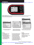


![VERUS PRO User Manual [3980kb PDF File] - Snap](http://vs1.manualzilla.com/store/data/005690474_1-9ff68923f14d7698ce72469cabae3990-150x150.png)