1
SCORBOT-ER VII
Before you install the DC servo gripper, make sure your Controller-A contains
the piggy-back board with 68020 CPU and 68881 FPU (floating point unit).
If the controller does not have these components, uppgrade the EPROMs in
Controller-A to Version F.44 or later.
After you have exchanged the EPROMs, you must configure the controller.
1.
Turn on the computer and the controller.
2.
Activate ATS.
3.
Enter the command HOME and make sure the routine is successfully completed.
The robot must be in the home position for the proper installation of the gripper.
Do not change the position of the robot after it is homed.
4.
Turn off the controller.
5.
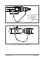
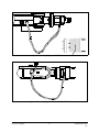
Using four M4x10 socket screws and a 3mm Allen key (hex wrench), attach the
gripper to the gripper mounting flange at the end of the robot arm, as shown in
the inset in Figure 1.
6.
Connect the gripper cable to the electrical connector on the robot arm.
Make sure the connector is oriented as shown in Figure 1.
7.
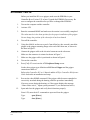
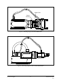
Make sure the gripper cable is positioned as shown in Figure 2.
8.
Turn on the controller.
Press [Shift]+F10 to activate the ATS Backup Manager.
9.
10.
Load the parameter file GRP7 from the ATS directory using the options:
“ Restore PARAMETERS” and “ RESTORE from disk (F5)” .
Execute the robot HOME command. If the gripper cable becomes entangled or
excessively stretched during the homing, abort the procedure immediately.
The gripper has a rotation of ±270°. Do not attempt to move the gripper beyond
this limit.
At the end of each work session (before turning off the controller), or before
homing the robot, make sure the gripper’s position is as shown in Figure 2.
Installation Guide
9903
-1-
DC Servo Gripper