1
.
Federated E-infrastructure Dedicated to European Researchers
Innovating in Computing network Architectures
Co-funded by the European Commission within the Seventh Framework
Programme. Grant Agreement No. RI-213107
Deliverable
DJRA1.3:
Tool
prototype
for
creating
and
stitching
multiple
network
resources
for
virtual
infrastructures
Version
3.1
Dissemination
Level
Contractual
Date
of
Delivery
Actual
Date
of
Delivery
Editors
Public
September
31st,
2010
December
23th,
2010
Cristina
Cervelló‐Pastor
(UPC)
Álvaro
Monje
(UPC)
Contributors
Reviewers
Ásgeir
Óskarsson
(UPC
Cristina
Cervelló‐Pastor
(UPC)
Álvaro
Monje
(UPC)
Ásgeir
Óskarsson
(UPC)
Robert
Machado
Calvo
(UPC)
Sebastià
Sallent
(UPC)
Jean‐Marc
Uze
(Juniper)
Dimitris
Kalogeras
(ICCS)
Markus
Hidell
(KTH)
Peter
Sjödin
(KTH)
Pehr
Söderman
(KTH)
Sergi
Figuerola
(i2CAT)
Josep
Pons
(i2CAT
Łukasz
Dolata
(PSNC)
Mauro
Campanella
(GARR)
Peter
Kauffman
(DFN)
Monika
Roesler
(DFN)
Susanne
Naegele‐Jackson
(DFN)
Constantinos
Vassilakis
(GRNET)
Mauro
Campanella
(GARR)
Page
1
of
100
.
Abstract
This
document
describes
the
prototype
FEDERICA
Slice
Tool
developed
for
the
virtualization
of
network
elements
in
FEDERICA
and
for
creating
and
stitching
network
resources
over
this
virtual
infrastructure.
An
SNMP‐based
resource
discovery
prototype
is
also
introduced
as
a
new
functionality
to
be
integrated
in
the
tool.
The
deliverable
also
presents
a
viability
study
for
the
use
of
traffic
prioritization
in
the
FEDERICA
infrastructure
and
some
network
performance
measurements
on
a
real
slice
within
FEDERICA.
Document
Revision
History
Version
Date
Description
of
change
Author
0.2
April
2010
Base
template
adapted,
Introduction
UPC
1.0
June
2010
Chapters
added
UPC
1.1
July
2010
Network
Discovery
Protocol
,
other
work
UPC
1.2
August
2010
Update
on
existing
chapters
UPC
1.3
September
2010
Network
Tests,
work
on
remaining
chapters
UPC
1.5
October
2010
All
chapters
complete.
Last
revision.
UPC
1.6
October
2010
Structural
adjustments
made
UPC
2.0
November
2010
Reviewed
and
edited.
Martel
3.1
December
2010
Reviewed,
Edited
and
approved
GARR
Page
2
of
100
.
Executive
Summary
This
document
reports
the
final
results
of
JRA1.2
Activity
in
the
development
of
a
tool
prototype
for
creating
sets
of
virtual
resources
in
FEDERICA.
The
prototype
goal
is
to
simplify
and
automate
part
of
the
work
for
NOC.
The
tool
may
also
serve,
with
different
privileges,
a
FEDERICA
user
to
operate
on
his/her
slice.
The
tool
has
been
developed
in
collaboration
with
task
TSA2.4,
which
reported
its
intermediate
development
status
in
Deliverable
SA2.2
“IP
slice
service
Prototype’
in
March
2009.
The
tool
manual
and
final
report
of
the
effort
are
contained
here
and
they
will
not
duplicated
in
DSA2.3,
as
the
effort
was
a
joint
effort
of
the
two
tasks
as
a
key
collaboration
between
the
two
activities.
The
Deliverable
DJRA2.4
“Final
prototype
testing”
is
a
complementary
technical
report
on
the
latest
IPsphere‐MANTICORE
interoperability
prototype
tests
based
on
the
FEDERICA
infrastructure,
to
assess
the
viability
of
a
FEDERICA
service
interoperability
with
the
IPsphere/TMF
framework.
The
tool
described
here
was
designed
with
the
objective
of
providing
an
interactive
application
with
a
graphical
interface
to
operate
on
resources
for
the
NOC
and
the
end
users
(researchers).
The
tool
simplify
the
creation
and
configuration
of
resources
in
a
slice
and
it
is
a
mandatory
step
to
ensure
scalability
of
the
NOC
effort.
It
offers
an
interactive
Graphical
User
Interface
that
translates
the
users’
actions
to
commands
in
the
substrate
(network
nodes
and
V‐nodes)
and
slice
elements
(Virtual
Machines).
User
accounts
may
be
created
for
the
NOC
and
for
researchers,
each
with
specific
privileges
to
enable
different
sets
of
capabilities.
The
NOC
account
has
full
access
to
all
the
resources
in
the
substrate,
while
each
user’
account
has
full
access
only
to
the
virtual
resources
in
his/her
slice
.
The
tool
has
been
developed
using
the
Java
programming
language
as
OpenSource
code
and
relies
on
the
open
source
Globus®
Toolkit.
Testing
has
been
performed
in
a
laboratory
environment
and
on
some
FEDERICA
substrate
equipment
(1
switch,
2
VMware
Servers)
in
their
standard
configuration.
For
testing
the
router,
web
services
and
GUI
an
additional
computer
was
used,
using
a
public
IP
address.
The
structure
of
the
deliverable
is
the
following:
−
−
−
−
−
−
Section
1,
after
the
executive
summary,
provides
a
brief
introduction.
Section
2
is
the
tool
manual
which
contains
also
a
general
description
of
its
use
and
functionalities.
The
manual
also
provides
a
description
of
functionalities
of
the
next
release,
not
officially
released.
Section
3
reports
an
SNMP‐based
resource
discovery
functionality
module,
which
is
not
yet
part
of
the
tool
and
will
be
integrated
into
the
tool
in
the
future.
It
aims
at
automating
the
addition
of
new
devices
to
the
substrate
or
slice.
The
source
code
of
this
resource
discovery
prototype
tool
is
available
in
Annex
A
of
this
document.
Section
4
draws
the
conclusions.
Annex
B
reports
a
study
for
the
use
of
traffic
prioritization
in
the
FEDERICA
network
infrastructure.
Various
Class
of
Service
and
Quality
of
Service
parameters
are
studied
provisioning
of
CoS/QoS
in
Layer
2.
This
is
intended
to
assess
the
feasibility
of
CoS/QoS
implementation
in
the
tool
Annex
C
present
the
specific
CoS/QoS
configuration
capabilities
and
commands
for
the
Junos
equipment.
Page
3
of
100
.
Table
of
Contents
Executive
Summary .................................................................................................. 3
List
of
Figures......................................................................................................... 6
List
of
Tables.......................................................................................................... 8
List
of
Abbreviations .............................................................................................. 8
1 Introduction ....................................................................................................... 9
2 FEDERICA
Slice
Tool
Manual.............................................................................. 10
2.1 Overview .................................................................................................... 10
2.1.1 Scope ................................................................................................... 10
2.1.2 FEDERICA
Slice
Tool
Functionalities ...................................................... 10
2.2 Getting
Started ........................................................................................... 12
2.2.1 Installation ........................................................................................... 12
2.2.2 Security
Setup ...................................................................................... 12
2.2.3 Logging
in............................................................................................. 13
2.2.4 Creating
Server
profiles........................................................................ 14
2.3 User
Management ...................................................................................... 15
2.3.1 Logging
in
for
the
first
time
after
installation........................................ 15
2.3.2 User
Management
Editor ..................................................................... 15
2.4 Substrate
Editor
Guide................................................................................ 20
2.4.1 Introduction ......................................................................................... 20
2.4.2 Create
a
new
Substrate ........................................................................ 24
2.4.3 Add
a
Physical
Device........................................................................... 25
2.4.4 Create
Substrate
Topology ................................................................... 28
2.4.5 Router
capabilities ............................................................................... 30
2.4.6 Computer
capabilities .......................................................................... 33
2.4.7 Ethernet
Switch
Capabilities................................................................. 40
2.4.8 Common
capabilities............................................................................ 54
2.5 Root
Resource
List
Editor
Guide .................................................................. 66
2.5.1 Add
resources
into
Slices...................................................................... 67
2.5.2 Add
resources
into
Networks ............................................................... 68
2.6 Slice
Editor
Guide........................................................................................ 68
2.6.1 Create
a
new
Slice ................................................................................ 68
2.6.2 Export
Slice .......................................................................................... 69
2.6.3 Release
Slice......................................................................................... 70
2.6.4 Add
resources
into
Networks ............................................................... 70
2.7 Network
Editor
Guide ................................................................................. 71
2.7.1 Network
Editor
Tour............................................................................. 71
2.7.2 Create
a
New
Network ......................................................................... 73
2.7.3 Modify
IPv4
Address ............................................................................ 74
2.7.4 Configure
OSPF .................................................................................... 74
Page
4
of
100
.
2.7.5 Configure
BGP...................................................................................... 76
2.7.6 Configure
Virtual
Machine
parameters................................................. 77
3 Network
Discovery
Protocol ............................................................................. 80
3.1 JUNOS
Configuration................................................................................... 80
3.2 Prototype
Implementation.......................................................................... 82
4 Conclusions ....................................................................................................... 83
References .............................................................................................................. 83
Annex
A.
Network
Discovery
Source
Code.............................................................. 84
Annex
B.
QoS
/
CoS
in
Layer
2................................................................................. 88
B.1 Layer
2
CoS
Only ......................................................................................... 88
B.2 FEDERICA
Slice
Tool
CoS
Scope
(NOC) ......................................................... 91
B.2.1
Traffic
Classification ................................................................................ 91
B.2.2
Traffic
Queuing ....................................................................................... 92
B.2.3
Traffic
Scheduling.................................................................................... 93
B.3 Possible
Use
Cases ...................................................................................... 94
B.3.1 CoS
configuration
with
firewall
filters
and
policers
over
a
VLAN........... 94
B.3.2 CoS
configuration
with
firewall
filters,
Forwarding
Classes
and
schedulers
for
Interfaces.................................................................................. 95
B.4
CoS
out
of
scope
FEDERICA
Slice
Tool
(NOC) .................................................. 95
Annex
C.
Configuring
CoS........................................................................................ 97
Page
5
of
100
.
List
of
Figures
Fig.
2‐1:
Login
Dialogue.................................................................................................................................13
Fig.
2‐2:
Edit
preferences ..............................................................................................................................14
Fig.
2‐3:
Edit
Server
preferences ..................................................................................................................14
Fig.
2‐4:
Edit
Server
Port
Preferences ..........................................................................................................15
Fig.
2‐5:
User
List ...........................................................................................................................................16
Fig.
2‐6:
User
Details .....................................................................................................................................16
Fig.
2‐7:
User
Management
Editor ...............................................................................................................17
Fig.
2‐8:
Create
New
User
Wizard ................................................................................................................18
Fig.
2‐9:
Modify
User
Window......................................................................................................................19
Fig.
2‐10:
Confirm
Prompt ............................................................................................................................20
Fig.
2‐11:
Graphical
Editor ............................................................................................................................21
Fig.
2‐12:
Outline
View..................................................................................................................................22
Fig.
2‐13:
Properties
View.............................................................................................................................23
Fig.
2‐14:
Physical
Substrate
Toobar ............................................................................................................23
Fig.
2‐15:
Substrate
Editor
Overview ...........................................................................................................24
Fig.
2‐16:
Create
New
Physical
Substrate
Button........................................................................................24
Fig.
2‐17:
Create
Physical
Substrate
Wizard ................................................................................................25
Fig.
2‐18:
Create
Physical
Device
Wizard.....................................................................................................26
Fig.
2‐19:
Physical
Device
Profile..................................................................................................................27
Fig.
2‐20:
Topology
Tool................................................................................................................................28
Fig.
2‐21:
Create
Physical
Link
Wizard .........................................................................................................29
Fig.
2‐22:
Physical
Link ..................................................................................................................................29
Fig.
2‐23:
General
physical
link
properties ..................................................................................................30
Fig.
2‐24:
Graphical
physical
link
properties................................................................................................30
Fig.
2‐25:
Create
Logical
Interfaces ..............................................................................................................31
Fig.
2‐26:
Create
logical
interface
Wizard....................................................................................................32
Fig.
2‐27:
Create
logical
router
wizard.........................................................................................................33
Fig.
2‐28:
Create
Port
Group.........................................................................................................................34
Fig.
2‐29:
Add
a
port
group
Wizard ..............................................................................................................34
Fig.
2‐30:
Add
Virtual
Switch ........................................................................................................................35
Fig.
2‐31:
Create
Virtual
Machine.................................................................................................................36
Fig.
2‐32:
Add
new
Virtual
Machine
Wizard................................................................................................36
Fig.
2‐33:
Copy
Virtual
Machine
Wizard ......................................................................................................37
Fig.
2‐34:
Create
new
virtual
Hard
Disk .......................................................................................................38
Fig.
2‐35:
Create
virtual
nic
Wizard ..............................................................................................................39
Fig.
2‐36:
Virtual
Machine
Editing
Options..................................................................................................40
Fig.
2‐37:
Ethernet
Switch
Capabilities ........................................................................................................41
Fig.
2‐38:
Create
Virtual
LAN
Wizard............................................................................................................42
Fig.
2‐39:
Configure
or
delete
existing
VLAN...............................................................................................43
Fig.
2‐40:
Configure
VLAN .............................................................................................................................44
Fig.
2‐41:
Configure
Switch
Interfaces .........................................................................................................45
Fig.
2‐42:
Ethernet
Switching
Options .........................................................................................................46
Fig.
2‐43:
Create
Logical
Switch
Wizard.......................................................................................................47
Fig.
2‐44:
Logical
Switch
in
Substrate
Network
Editor................................................................................48
Fig.
2‐45:
Configure
Class
of
Service
(Toolbar)............................................................................................48
Fig.
2‐46:
Configure
Class
of
Service ............................................................................................................49
Page
6
of
100
.
Fig.
2‐47:
Create
Forwarding
Class...............................................................................................................49
Fig.
2‐48:
Create
Scheduler...........................................................................................................................50
Fig.
2‐49:
Create
Scheduler
Map ..................................................................................................................50
Fig.
2‐50:
Add
new
Scheduled
Interface ......................................................................................................51
Fig.
2‐51:
Configure
Filters
&
Policers ..........................................................................................................52
Fig.
2‐52:
Assign
Filters
Wizard.....................................................................................................................53
Fig.
2‐53:
Explore
Devices .............................................................................................................................54
Fig.
2‐54:
Explore
Router ..............................................................................................................................55
Fig.
2‐55:
Explore
VMWare
Server ...............................................................................................................56
Fig.
2‐56:
Explore
Switch ...............................................................................................................................57
Fig.
2‐57:
Create
Virtual
Interface ................................................................................................................58
Fig.
2‐58:
Create
Virtual
Interface
Wizard ...................................................................................................59
Fig.
2‐59:
Configure
Interface
Properties ....................................................................................................59
Fig.
2‐60:
Virtual
Interface
Summary ...........................................................................................................60
Fig.
2‐61:
Create
Virtual
Link ........................................................................................................................61
Fig.
2‐62:
Create
Virtual
Link
‐
Select
Logical
Device ..................................................................................62
Fig.
2‐63:
Configure
Virtual
Link
Properties.................................................................................................63
Fig.
2‐64:
Create
Virtual
Link
Summary .......................................................................................................63
Fig.
2‐65:
Erroneous
Device
Icon..................................................................................................................64
Fig.
2‐66:
De‐synchronization
Problems ......................................................................................................64
Fig.
2‐67:
Editor
Preferences ........................................................................................................................65
Fig.
2‐68:
Root
Resource
List
Editor .............................................................................................................66
Fig.
2‐69:
Example
of
virtualized
link ...........................................................................................................67
Fig.
2‐70:
Assign
To
Slice
Wizard ..................................................................................................................68
Fig.
2‐71:
Create
New
Slice ...........................................................................................................................68
Fig.
2‐72:
Create
Slice
Wizard .......................................................................................................................69
Fig.
2‐73:
Export
Slice
Wizard .......................................................................................................................69
Fig.
2‐74:
NOC
View
Exported
Slices ............................................................................................................70
Fig.
2‐75:
Assign
to
Network
Wizard............................................................................................................71
Fig.
2‐76:
Graphical
Network
Editor.............................................................................................................72
Fig.
2‐77:
Create
New
Network ....................................................................................................................73
Fig.
2‐78:
Create
Network
Wizard ................................................................................................................73
Fig.
2‐79:
Modify
IPv4
Wizard.......................................................................................................................74
Fig.
2‐80:
Configure
OSPF
Wizard.................................................................................................................75
Fig.
2‐81:
Configure
OSPF
Wizard
‐
2 ...........................................................................................................76
Fig.
2‐82:
BGP
Wizard....................................................................................................................................77
Fig.
2‐83:
VM
Virtual
Node
Options .............................................................................................................77
Fig.
2‐84:
Add
CD‐ROM
iso
to
VM ................................................................................................................78
Fig.
2‐85:
Add
CD‐ROM
OS
iso
to
VM...........................................................................................................78
Fig.
2‐86:
Manual
Synchronization...............................................................................................................79
Fig.
B‐1:
CoS
scenario ....................................................................................................................................89
Fig.
B‐2:
JUNOS
software
process
of
CoS
components...............................................................................91
Fig.
B‐3:
Interface
traffic
classification.........................................................................................................92
Fig.
B‐4:
Scheduler
Map ................................................................................................................................93
Fig.
B‐5:
CoS
configuration
with
firewall
filters
and
policers .....................................................................94
Fig.
B‐6:
CoS
configuration
with
firewall
filters,
Forwarding
Classes
and
schedulers ..............................95
Page
7
of
100
.
List
of
Tables
Table
1:
Queues
default
configuration
of
EX‐3200
switch .........................................................................93
List
of
Abbreviations
BGP
–
Border
Gateway
Protocol
CoS
–
Class
of
Service
FUP
–
FEDERICA
User
Portal
GUI
–
Graphical
User
Interface
IaaS
–
Infrastructure
as
a
Service
NIC
–
Network
Interface
Controller
NOC
–
Network
Operations
Centre
NREN
–
National
Research
and
Education
Network
OSPF
–
Open
Shortest
Path
First
QoS
–
Quality
of
Service
RPC
–
Remote
Procedure
Call
RVI
–
Routed
VLAN
Interfaces
SHA
–
Secure
Hash
Algorithm
SNMP
–
Simple
Network
Management
Protocol
TCP
–
Transmission
Control
Protocol
UCLP
–
User
Controlled
Lightpath
Provisioning
UDP
–
User
Datagram
Protocol
URL
–
Uniform
Resource
Locator
UAS
–
User
Access
Server
VLAN
–
Virtual
Local
Area
Network
VM
–
Virtual
Machine
VMDK
–
Virtual
Machine
Disk
VI
–
Virtual
Infrastructure
XML
–
eXtensible
Markup
Language
XORP
–
eXtensible
Open
Router
Platform
Page
8
of
100
.
1
Introduction
The
previous
deliverable
DJRA1.2
“Solutions
and
protocols
proposal
for
the
network
control,
management
and
monitoring
in
a
virtualized
network
context”
focused
on
research
in
various
areas,
such
as
resource
discovery,
monitoring,
routing,
etc.
Once
the
virtualization
of
network
elements
and
infrastructures
is
possible,
the
next
step
is
to
allow
stitching
resources
across
different
PoPs
within
the
FEDERICA
substrate.
The
tool
has
been
developed
to
allow
a
partially
automated
and
simplified
creation
of
virtual
infrastructures
in
the
FEDERICA
substrate.
Further
investigations
into
possible
improvements
of
the
tool
are
also
being
made.
Page
9
of
100
.
2
FEDERICA
Slice
Tool
Manual
This
chapter
includes
the
complete
user
manual
for
the
FEDERICA
Slice
Tool.
It
is
a
very
extensive
manual
describing
all
the
possibilities
within
the
tool,
accompanied
by
illustrations
to
help
the
user
configure
and
use
it.
The
first
section
describes
an
overview
of
the
first
steps
in
order
to
get
started.
The
other
sections
describe
different
segments
of
the
tool.
The
complete
source
code
of
the
tool
can
be
downloaded
from
the
FEDERICA
Wiki.
2.1
Overview
2.1.1
Scope
The
tool
was
designed
with
the
objective
of
providing
both
the
Network
Operations
Center
(NOC)
and
the
end
users
(researchers)
a
set
of
functionalities
to
configure
and
manage
slices.
The
FEDERICA
Slice
Tool
allows
the
configuring
of
a
substrate
and
slices
from
an
integrated
GUI
where
the
user
can
send
all
necessary
commands
to
the
devices
(routers,
switches
and
Virtual
Machines
(VMs))
in
order
to
accomplish
the
needs
of
the
NOC
and
the
researchers.
There
are
two
types
of
user
accounts
in
differentiating
between
NOC
and
researcher
users.
The
Administrator
account
is
the
only
one
capable
of
creating
researcher
accounts.
Additionally,
the
tool
offers
virtualization
capabilities
in
order
to
create
slices
for
the
researchers.
In
the
section
below,
the
basic
functionalities
are
explained.
The
integration
of
VMWare
Servers
and
VMs
in
the
tool
has
been
accomplished
by
i2Cat,
while
UPC
has
completed
the
integration
of
the
Juniper
EX3200
switches.
As
routers
have
already
been
implemented,
they
only
needed
to
be
integrated
in
the
tool
which
was
done
by
UPC.
The
tool
has
been
tested
in
all
functionalities
mentioned
in
the
document
for
each
layer
(engine,
Web
Services,
GUI).
For
the
switch
tests
and
VMWare
Servers,
actual
FEDERICA
substrate
equipment
and
their
FEDERICA
IP
addresses
was
used
(1
switch,
2
VMWare
Servers).
For
the
router,
web
services
and
GUI,
a
test
pc
was
used
with
a
public
IP.
The
limitations
during
the
tests
(limited
availability
of
switches,
use
of
VMs
for
routers
instead
of
actual
Juniper
M7i
routers)
imply
that
some
functionality
might
present
deficiencies,
especially
regarding
the
integration
of
the
existing
tool.
2.1.2
FEDERICA
Slice
Tool
Functionalities
FEDERICA
Slice
Tool
functionalities
differ
for
the
type
of
user
interacting
with
it.
Therefore,
the
functionalities
can
be
seen
from
two
different
points
of
view:
the
NOC
and
the
user.
Page
10
of
100
.
2.1.2.1
NOC
functionalities
‐
User
management:
As
mentioned
in
section
2.1.1,
the
Network
Operation
Center
(NOC)
is
able
to
manage
user
accounts
by
creating,
modifying
or
deleting
users
(researchers).
These
users
belong
to
“Organizations”.
It
is
possible
to
create
one
or
more
researcher
users
for
the
same
organization.
This
functionality
allows
different
users
of
the
same
organization
to
operate
on
the
slices.
For
example,
user
A
and
user
B
of
the
organization
X
can
configure
slice
W
with
his/her
own
user
account.
‐
Add
devices:
Juniper
M7i
routers,
Juniper
EX‐3200
switches
and
VMWare
Servers
can
be
added
to
the
substrate.
The
NOC
must
introduce
its
host
name,
transport,
protocol,
username
and
password
in
order
to
obtain
its
configuration.
The
NOC
can
access
the
physical
devices
after
configuration.
‐
Configure
devices:
The
NOC
is
able
to
operate
over
the
physical
devices
already
added
into
the
substrate.
For
example,
the
NOC
can
create
for
routers
logical
interfaces,
tunnels,
logical
routers,
etc.
and
configure
them.
For
switches,
logical
switches
and
VLANs
can
be
created
and
CoS
parameters
can
be
modified.
Also,
VMs
can
be
created
on
VMWare
Servers
and
its
server
parameters
can
be
configured
(number
of
Hard
Drives,
Disk
space,
etc).
For
more
detailed
information,
see
the
“Substrate
Editor
Guide”
section
inside
the
tool
manual.
‐
Maintain
substrate
configuration:
The
FEDERICA
Slice
Tool
allows
the
creating
of
physical
links
between
physical
devices.
Thus,
the
NOC
can
view
and
maintain
the
FEDERICA
infrastructure.
‐
Virtualize:
The
FEDERICA
Slice
Tool
provides
virtualization
capabilities
needed
for
slice
creation.
NOC
can
virtualize
links
and
interfaces
of
the
physical
and/or
logical
devices.
For
example,
if
we
have
a
physical
link
between
a
VMWare
server1
and
router1,
it
can
be
virtualized
as
a
link
between
VM1
(from
VMWare
server1)
and
interface
ge‐0/0/0.1
of
logical
router1
which
belongs
to
router1.
‐
Root
resource
list:
This
tracks
the
substrate’s
virtualized
elements.
Physical
and
logical
devices
are
represented
as
Virtual
Nodes.
In
this
view
of
the
tool,
virtualized
links
and
interfaces
will
also
be
shown
in
order
to
assign
them
to
slices.
‐
Assign
to
slices:
Virtualized
elements
of
the
Root
resource
list
view
can
be
assigned
to
slices,
providing
the
division
of
the
virtualized
elements
in
the
infrastructure
(or
substrate).
‐
Export/Release
slices:
Once
the
NOC
has
mapped
a
researcher’s
requested
resources
into
a
slice,
the
request
should
be
exported
in
order
to
become
visible
for
the
end
user.
As
stated
previously,
slices
are
exported
to
organizations
and,
once
the
exportation
is
complete,
then
all
organization
members
will
be
able
to
configure
those
exported
slices
once
they
log
in
with
their
researcher
account.
The
opposite
Page
11
of
100
.
action
can
be
done
by
the
NOC:
upon
un‐exporting
(or
releasing)
a
slice,
the
researcher
is
no
longer
able
to
see
slices
previously
exported
to
his
organization.
‐
Support
functionalities:
A
set
of
secondary
functionalities
are
available
for
the
NOC
in
order
to
support
and
aid
in
the
management
of
the
substrate
and
slices.
Examples
are
synchronizing
devices,
identify
problems,
colour
differentiation
of
Virtual
Nodes
by
device
type,
profiles,
etc.
2.1.2.2
Researcher
functionalities
‐
View
slice
topology:
Once
the
researcher
logs
in,
a
view
of
all
slices
that
belong
to
his
organization
can
be
seen.
For
each
slice,
Virtual
Nodes
(routers,
switches
and
VMs),
links
and
interfaces
can
be
seen
in
the
slice
view.
‐
Configure
network(s)
of
the
slice:
In
order
to
operate
over
the
slice,
the
end
user
must
create
a
network
and
then
assign
to
it
resources.
Configuration
will
be
done
on
the
network
view.
Usually
a
slice
corresponds
to
a
network,
but
the
researcher
is
able
to
divide
slice
resources
into
two
or
more
networks
if
desired.
‐
IP
configuration:
A
researcher
is
able
to
configure
layer
3
parameters
of
resources
(IPs,
OSPF,
BGP)
and
can
power
on
and
set
some
parameters
of
the
VMs
assigned
to
him/her.
‐
Support
functionalities:
As
with
NOC
functionalities,
researchers
have
support
actions
such
as
synchronize
slice
nodes,
view
any
problems,
colour
differentiation
of
nodes
by
type,
etc.
The
previous
(and
other
specific)
functionalities
are
explained
in
further
detail
in
the
next
sections
of
the
FEDERICA
Slice
Tool
manual.
2.2
Getting
Started
2.2.1
Installation
To
start
the
installation
of
the
FEDERICA
Slice
Tool,
the
user
should
double
click
on
the
executable
file
and
simply
follow
the
instructions
of
the
installation
wizard.
These
will
not
be
explained
further
in
this
manual.
2.2.2
Security
Setup
Page
12
of
100
.
Once
installation
is
complete,
it
is
necessary
to
install
Globus
toolkit
4.2.1
in
order
to
run
the
FEDERICA
Slice
Tool.
Globus
toolkit
4.2.1
is
an
open‐source
toolkit
which
can
be
downloaded
from
http://www.globus.org/toolkit/.
The
first
time
you
execute
the
GUI,
a
new
folder
will
be
created
in
USER_HOME
at
/.globus/.
In
order
to
accept
the
certificate
created
in
the
server
where
the
services
are
placed,
it
is
necessary
to
copy
the
files
“SERVERNAME‐CAcer.0”
and
“SERVERNAME‐CAcert.signing_policy”
in
the
folder:
USER_HOME/.globus/certificates/
2.2.3
Logging
in
Upon
launching
the
FEDERICA
Slice
Tool,
the
user
will
be
required
to
log
in
before
gaining
access
to
the
system.
Before
one
can
log
in,
a
FEDERICA
user
account
must
have
been
created
by
the
administrator.
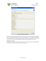
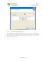
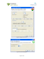
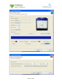
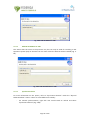
When
presented
with
the
login
dialogue
(Fig.
2‐1),
the
user
must
enter
the
Login
ID
and
password,
and
then
enter
the
host
name
and
port
number
of
the
server
that
the
user
Management
Web
Service
is
located
on.
It
is
also
possible
to
select
these
settings
from
the
combo
boxes
containing
the
stored
preferences.
After
entering
the
host
name
and
port,
click
the
Login
button.
The
system
will
contact
the
server
to
validate
the
username
and
password
and
if
successful,
will
launch
the
FEDERICA
Slice
Tool
GUI.
If
the
data
entered
is
erroneous,
an
error
message
will
appear.
Fig.
2‐1:
Login
Dialogue
Page
13
of
100
.
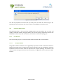
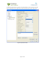
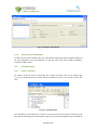
2.2.4
Creating
Server
profiles
After
a
successful
login,
the
application
will
store
the
IP
address
and
port
number
with
the
server
preferences.
To
edit
these
preferences,
go
to
Window
/
Preferences
(Fig.
2‐2),
select
Servers
and
choose
to
edit
the
IP
Preferences
or
the
Port
preferences
(Fig.
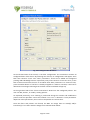
2‐3).
Fig.
2‐2:
Edit
preferences
Fig.
2‐3:
Edit
Server
preferences
Both
preference
editors
work
in
the
same
manner;
to
add
an
element
to
the
list
write
it
in
the
field
under
the
list
and
then
click
on
Add
to
List;
to
remove
an
element,
it
has
to
be
selected
from
the
list
and
clicked
to
Remove
Selection.
All
the
list
elements
can
be
placed
in
Page
14
of
100
.
order
using
the
rows
situated
on
the
right
of
the
list.
After
all
changes
are
made,
click
on
the
Apply
button
to
store
the
changes.
If
there
is
a
problem,
an
error
message
will
appear
(Fig.
2‐4).
Fig.
2‐4:
Edit
Server
Port
Preferences
2.3
User
Management
The
FEDERICA
Slice
Tool
is
based
on
the
User
Controlled
Lightpath
Provisioning
Tool
(www.uclp.ca),
therefore
user
accounts
are
maintained
on
a
server
that
communicates
with
the
UCLP
Management
Center
when
logging
in
and
for
editing
user
accounts.
There
are
two
types
of
user
accounts
that
can
be
created:
Administrator
and
Researcher.
Administrator
accounts
have
access
to
more
operations
than
researcher
accounts.
This
section
explains
how
to
implement
the
user
management.
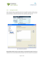
2.3.1
Logging
in
for
the
first
time
after
installation
When
the
User
Management
Web
Service
is
installed
for
the
first
time,
a
default
user
account
is
automatically
created.
This
account
has
full
administrative
access
to
the
system.
After
the
basic
installtion
has
ended,
the
user
can
login
using
in
this
account
to
setup
other
Administrator
and
Researcher
accounts.
As
soon
as
you
create
the
first
Administrator
account,
you
should
modify
the
default
password
to
avoid
unauthorized
access
to
the
system.
The
login
ID
for
the
default
account
is
as
follows:
User
name:
admin
Password:
password
2.3.2
2.3.2.1
User
Management
Editor
User
Types
There
are
2
different
types
of
user
accounts,
with
different
characteristics.
NOC
Administrator:
The
NOC
administrator
is
the
top
level
account.
The
NOC
Administrator
has
access
to
all
operations
on
the
system.
Only
NOC
Administrators
are
able
to
create
and
edit
substrate
networks.
Researcher:
A
researcher
is
a
member
of
an
organization
that
does
not
have
its
own
substrate
network.
These
organizations
typically
receive
a
slice
from
a
NOC
administrator
Page
15
of
100
.
and
use
it
to
manipulate
the
resources
creating
networks.
They
cannot
add
new
resources
or
change
any
of
the
resources
in
the
given
slice.
The
User
Management
Editor
can
be
opened
by
selecting
User
Management
from
the
menu
or
by
clicking
the
icon
on
the
toolbar.
Before
the
editor
can
open,
it
will
call
the
server
to
obtain
all
the
user
accounts
that
you
have
access
to
view.
If
you
are
logged
in
as
a
NOC
Administrator,
then
you
will
be
able
to
view
and
edit
all
users.
If
you
are
logged
in
as
a
researcher,
you
will
not
have
any
access
to
other
users.
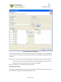
When
the
user
accounts
have
been
downloaded,
the
editor
will
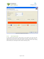
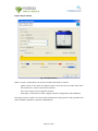
appear.
The
accounts
are
shown
in
a
list
(Fig.
2‐5),
first
by
user
type
and
then
alphabetically.
Fig.
2‐5:
User
List
By
selecting
a
user
name
from
the
list,
the
details
about
that
user
will
be
displayed
on
the
right
hand
side
of
the
screen
(Fig.
2‐6).
Fig.
2‐6:
User
Details
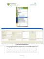
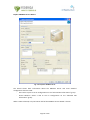
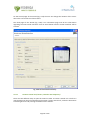
The
full
User
Management
Editor
will
look
as
follows
(Fig.
2‐7):
Page
16
of
100
.
Fig.
2‐7:
User
Management
Editor
Adding,
modifying
and
deleting
users
New
users
can
be
added
by
clicking
the
Add
User
button.
Existing
user
accounts
can
be
modified
or
deleted
by
clicking
the
Modify
User
or
Delete
User
button
located
under
the
selected
user’s
details.
Adding
New
Users:
To
add
a
new
user
account,
click
the
Add
User
button
next
to
the
User
List.
This
will
launch
the
Create
New
User
wizard
(Fig.
2‐8).
Only
NOC
Administrators
can
create
new
accounts.
Researchers
cannot
create
new
user
accounts
at
all.
2.3.2.2
Page
17
of
100
.
Fig.
2‐8:
Create
New
User
Wizard
At
the
top
of
the
wizard,
the
type
of
user
account
to
be
created
can
be
selected.
The
fields
in
the
wizard
must
be
filled
and
then
click
Finish
to
add
the
user.
The
Finish
button
will
only
become
enabled
when
all
required
fields
have
been
filled
out.
These
fields
are
marked
with
an
asterisk.
If
the
new
user
was
created
successfully,
it
will
be
added
to
the
User
List.
Modify
User
Accounts:
To
modify
a
user
account,
select
the
user
from
the
User
List
that
you
wish
to
modify
and
click
the
Modify
button
below
the
User
Details
Section
(Fig.
2‐9).
Page
18
of
100
.
Fig.
2‐9:
Modify
User
Window
As
with
adding
new
users,
the
eight
fields
marked
with
an
asterisk
are
required
and
cannot
be
left
blank.
The
user
type
and
user
name
cannot
be
modified.
If
you
want
to
modify
these,
the
account
should
be
deleted
and
a
new
one
should
be
created.
You
will
also
notice
that
the
password
string
is
likely
much
longer
than
what
was
entered
initially
when
the
account
was
created
or
when
you
logged
in.
This
is
because
all
passwords
are
encrypted
using
SHA
encryption.
The
password
can
be
changed,
but
make
certain
to
completely
delete
the
field
in
order
to
remove
all
the
encrypted
characters
before
retyping
the
new
one.
The
new
one
will
be
encrypted
when
the
Finish
button
is
clicked.
From
the
moment
the
Finish
button
on
the
“Add
or
Modify
User”
Wizard
is
clicked,
the
password
is
never
displayed
in
plain
text
again.
Delete
User
Accounts:
To
delete
a
user
account,
select
the
user
from
the
User
List
that
you
wish
to
delete
and
click
the
Delete
button
below
the
User
Details
Section.
Page
19
of
100
.
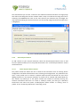
Fig.
2‐10:
Confirm
Prompt
You
will
be
prompted
to
confirm
that
you
really
want
to
delete
the
account
(Fig.
2‐10).
Selecting
Yes
will
remove
the
user
from
the
User
List
and
delete
it
from
the
server.
2.4
Substrate
Editor
Guide
The
Substrate
Editor
is
the
part
of
the
FEDERICA
Slice
Tool
that
allows
you
to
create
and
modify
a
substrate
network.
Using
this
editor,
the
user
can
specify
a
map
and
a
name
for
the
FEDERICA
infrastructure,
add
new
devices,
and
draw
the
substrate
topology,
etc.
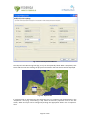
2.4.1
Introduction
This
section
will
give
you
an
overview
of
the
substrate
editor
and
its
functionalities.
2.4.1.1
Graphical
Editor
The
graphical
editor
allows
the
user
to
graphically
represent
and
edit
a
substrate
network.
A
background
image
to
be
the
network
map
can
be
specified,
icons
can
be
added
to
represent
the
devices
and
lines
can
be
drawn
to
represent
the
physical
topology.
This
editor
is
also
used
to
create
the
logical
resources
for
the
network,
i.e.
lightpaths,
and
to
interface
to
Web
Services.
Page
20
of
100
.
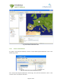
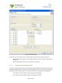
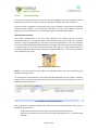
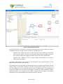
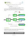
Fig.
2‐11:
Graphical
Editor
The
graphical
editor
(Fig.
2‐11)
is
structured
in
two
parts:
the
editing
area
and
the
palette.
The
palette
provides
the
user
with
tools
to
perform
the
editing
process.
The
palette
is
a
"flyout
palette"
i.e.
when
the
user
does
not
want
to
use
any
of
the
tools,
it
can
be
hidden
by
pressing
the
black
arrow
located
at
the
right
side
of
the
palette
name.
The
palette
has
3
types
of
tools:
‐
Selection
Tool:
Allows
the
selection
of
elements
that
are
on
the
editor.
The
editor
can
be
paned
by
pressing
and
holding
the
space
key
and
then
clicking
and
dragging
the
editor
area
to
move
the
viewable
area.
‐
Marquee
Tool:
Allows
the
selection
of
multiple
devices
by
selecting
a
square
area
of
the
editor.
There
are
three
Marquee
tools
available
by
clicking
the
arrow
to
the
right
of
the
Marquee
tool
1.
Select
only
nodes
(default)
2.
Selects
links
only
3.
Selects
both
nodes
and
links
‐
Topology
Tool:
Allows
the
drawing
of
a
physical
connection
between
two
devices
(by
clicking
first
on
the
originating
node,
then
on
the
destination
node).
Just
below
the
tools,
there
is
a
"drawer"
with
multiple
physical
devices.
New
devices
to
the
editor
can
be
added
by
selecting
the
element
in
the
palette
and
clicking
the
location
of
the
map
where
the
device
needs
to
be
placed.
Changes
to
the
layout
and
the
palette
settings
can
be
made
by
right
clicking
anywhere
on
the
palette
and
selecting
the
desired
options.
Page
21
of
100
.
The
editing
area
provides
some
features,
such
as
the
ability
to
drag
a
device
and
drop
it
wherever
desired
and
the
ability
to
zoom
in
and
out.
The
editing
area
can
be
extended
infinitely,
even
outside
the
borders
of
the
background
image,
by
selecting
a
device
and
dragging
it
beyond
the
editor
boundaries.
Right‐clicking
the
editor
or
its
components
will
cause
a
context
menu
to
appear,
with
options
depending
on
which
device(s)
and
physical
connection(s)
are
currently
selected.
2.4.1.2
Outline
View
The
outline
view
(Fig.
2‐12)
provides
another
view
of
the
physical
substrate.
It
is
a
tree
viewer
that
shows
all
the
devices
in
the
substrate.
Each
element
in
the
outline
can
be
expanded
to
show
its
internal
resource
structure
i.e.
slots,
ports,
channels,
VLANs.
When
expanded
to
show
the
channel,
the
current
state
of
that
channel
is
also
shown.
A
resource
can
be
also
selected
to
show
all
of
its
state
in
the
properties
view.
Fig.
2‐12:
Outline
View
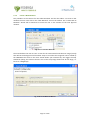
2.4.1.3
Properties
View
The
properties
view
(Fig.
2‐13)
gives
information
about
the
resource
either
in
the
graphical
editor
or
in
the
outline
view.
For
example,
if
a
device
is
selected,
information
regarding
its
name,
location,
element
type,
URL,
etc.
will
be
displayed.
Specific
fields
can
also
be
edited
by
clicking
the
value
which
needs
to
be
changed.
Page
22
of
100
.
Fig.
2‐13:
Properties
View
2.4.1.4
Physical
Substrate
Toolbar
There
is
a
context
specific
menu
for
physical
substrate
as
well
as
a
context
specific
toolbar
(Fig.
2‐14).
Fig.
2‐14:
Physical
Substrate
Toobar
It
is
possible
to
change
the
following:
zoom,
the
background
map,
view
the
details
of
a
substrate
device,
create
and
delete
a
logical
tunnel
interfaces,
logical
interfaces
and
logical
routers,
create
a
new
Virtual
Interface,
a
new
Virtual
Link,
and
configure
CoS
parameters,
etc.
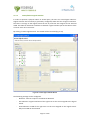
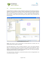
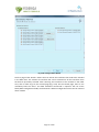
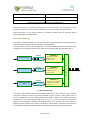
Fig.
2‐15
shows
the
editor
and
the
two
views
together
in
one
screen.
Page
23
of
100
.
Fig.
2‐15:
Substrate
Editor
Overview
2.4.2
Create
a
new
Substrate
To
create
a
new
physical
substrate,
click
the
"Create
New
Physical
Substrate"
icon
on
the
toolbar
(Fig.
2‐16).
Fig.
2‐16:
Create
New
Physical
Substrate
Button
The
"Create
New
Physical
Substrate"
wizard
(Fig.
2‐17)
will
be
launched
to
assist
in
the
creation
of
the
new
physical
substrate.
Page
24
of
100
.
The
wizard
allows
you
to
enter
a
name
for
the
substrate
network
and
select
an
image
(map)
that
will
be
the
background
of
the
network
editor.
Keep
in
mind
that
the
image
will
not
be
scaled
by
the
FEDERICA
Slice
Tool
so
the
more
devices
your
substrate
has,
the
bigger
the
map
should
be
(taking
into
account
that
the
size
of
the
map
image
should
not
be
larger
than
1
Megabyte).
Fig.
2‐17:
Create
Physical
Substrate
Wizard
2.4.3
Add
a
Physical
Device
To
add
a
device
to
your
physical
substrate,
select
the
desired
physical
device
icon
to
add
from
the
palette
and
drop
it
to
the
preferred
location.
The
"Create
Physical
Device"
wizard
will
be
launched.
2.4.3.1
Create
Physical
Device
wizard
The
profile
combo
box
allows
the
user
to
load
all
the
information
from
an
existing
device
configuration.
All
fields
will
be
filled
in
when
selecting
one
configuration.
If
a
profile
does
not
exist,
a
new
profile
can
be
created.
A
Physical
Device
profile
will
benefit
the
user
when
adding
the
device
in
the
physical
substrate.
A
profile
can
be
created
and
loaded
down
for
this
element
by
selecting
it
in
the
profile
combo
box
instead
of
manually
entering
the
element
information
each
time.
To
create
or
modify
a
profile,
you
must
go
to
Window/
Preferences
and
select
the
option
“Profile/Physical
Device
Profile”
or
clicking
“save
as
profile”
in
the
“Create
Physical
Device”
wizard
(Fig.
2‐18).
Page
25
of
100
.
Fig.
2‐18:
Create
Physical
Device
Wizard
Information
can
be
entered
in
the
fields
(Fig.
2‐19).
Note
that
the
Physical
Device
Name
must
not
be
left
empty.
If
“Virtual
transport”
is
selected
in
the
“Transport
Protocol”
field,
there
is
no
real
connection
with
devices.
This
functionality
is
useful
for
testing
due
to
avoiding
connection
time
and
is
supported
by
Juniper
routers
and
switches.
Other
fields
are
self
explanatory.
After
finishing,
click
on
Add
to
List
to
store
this
element
profile.
If
there's
an
error
in
the
IP
Address,
or
the
port
or
if
the
name
is
already
on
the
list,
the
application
will
inform
the
user
and
will
not
allow
it
to
be
added.
To
modify
an
existing
element
profile,
just
select
the
element
from
the
list,
update
the
fields
and
finally
click
on
Save
Changes.
(It
is
important
to
click
on
the
button
for
every
element
profile
modified).
To
delete
a
device
profile,
just
select
the
element
from
the
list
and
click
the
button
Remove
Selection.
There
is
another
button
that
clears
all
the
information
fields.
In
this
case,
when
creating
different
profiles,
the
user
will
not
need
to
delete
every
field
manually
Upon
completion,
the
device
icon
will
appear
on
the
map
at
the
selected
location.
The
location
of
the
device
can
be
changed
by
dragging
and
dropping
it
to
a
desired
place
or
by
changing
its
x,y
coordinates
in
the
"Properties"
view.
Also,
if
the
device
is
selected,
other
data
in
the
device
can
be
changed
using
the
"Properties"
view.
Page
26
of
100
.
To
delete
the
physical
device,
right
click
it
and
select
delete,
or
click
it
and
press
the
"DEL"
key.
To
undo/redo
an
action,
right
click
the
editor
and
select
either
the
left
or
right
arrow.
Fig.
2‐19:
Physical
Device
Profile
Page
27
of
100
.
2.4.4
Create
Substrate
Topology
The
topology
of
the
substrate
is
created
using
the
Topology
Tool
in
the
Physical
Substrate
Editor
(Fig.
2‐20).
To
manually
create
the
substrate
topology,
select
the
Topology
Tool
from
the
palette
in
the
Physical
Substrate
Editor,
click
on
the
first
physical
device
you
are
connecting,
and
then
click
on
the
second
one.
A
line
appears
after
clicking
on
the
device.
Follow
the
cursor
to
the
second
element.
Fig.
2‐20:
Topology
Tool
In
order
to
connect
when
both
devices
are
selected,
the
“Create
Physical
Link”
wizard
(Fig.
2‐21)
will
appear.
The
port
for
each
device
that
this
physical
link
is
on
must
then
be
entered.
Page
28
of
100
.
Fig.
2‐21:
Create
Physical
Link
Wizard
The
Physical
Link
Monitoring
field
(Fig.
2‐22)
can
be
optionally
filled.
When
completed,
click
Finish
and
the
new
line
showing
the
physical
link
between
the
two
devices
will
be
displayed.
Fig.
2‐22:
Physical
Link
If
a
physical
link
is
selected
using
the
Selection
Tool,
its
properties
will
be
displayed
in
the
“Properties”
view
(Fig.
2‐23
and
Fig.
2‐24).
Some
of
the
link's
properties
such
as
the
link
colour,
width
and
style
can
be
changed
by
clicking
the
appropriate
field
in
the
“Properties”
view.
Page
29
of
100
.
Fig.
2‐23:
General
physical
link
properties
Fig.
2‐24:
Graphical
physical
link
properties
If
the
physical
link
needs
to
be
deleted,
right‐click
it
and
select
delete,
or
left‐click
it
and
press
the
"DEL"
key.
To
undo/redo
an
action
you
must
right‐click
the
editor
and
select
either
the
left
or
right
arrow
(or
press
CTRL‐Z
for
undo
and
CTRL‐Y
for
redo).
2.4.5
Router
capabilities
Once
a
router
for
the
substrate
is
created,
the
desired
configuration
to
this
device
can
be
applied.
The
several
options
are
explained
in
the
following
sections.
2.4.5.1
Create
a
logical
interface
There
are
two
options
available
to
open
the
“Create
logical
interface”
wizard:
right‐clicking
over
the
specific
router
and
selecting
“Create
logical
interfaces”
(Fig.
2‐25)
or
selecting
the
specific
router
and
pressing
the
“Create
logical
interfaces”
button
in
the
toolbar.
Page
30
of
100
.
Fig.
2‐25:
Create
Logical
Interfaces
The
wizard
is
shown
in
Fig.
2‐26.
In
the
wizard,
a
logical
interface
can
be
created
from
a
physical
or
a
logical
router.
If
the
option
“None”
in
the
combo
box
from
the
field
“Select
the
logical
router”
is
selected,
this
specifies
that
the
logical
interfaces
will
be
created
over
the
physical
router.
Otherwise,
if
any
of
the
logical
routers
of
the
physical
router
are
selected,
the
logical
interfaces
will
be
created
over
the
selected
logical
router.
The
next
field
is
the
“Select
the
port”,
the
port
over
which
the
logical
interface
will
be
created.
Finally,
the
field
“Logical
tag”
to
define
the
tag
of
the
logical
interface
is
displayed.
Once
all
the
fields
have
been
completed,
click
on
the
Finish
button
and
the
logical
interface
will
be
created.
Page
31
of
100
.
2.4.5.2
Fig.
2‐26:
Create
logical
interface
Wizard
Create
a
logical
router
As
with
creating
logical
interfaces,
logical
routers
can
be
created
in
the
same
two
ways:
right‐clicking
over
the
physical
router
and
selecting
the
option
“Create
logical
router”
or
selecting
the
physical
router
and
clicking
the
button
“Create
logical
routers”.
After
clicking
either
of
these,
the
“Create
logical
router”
wizard
is
shown
(Fig.
2‐27).
Page
32
of
100
.
Fig.
2‐27:
Create
logical
router
wizard
There
are
only
two
fields
which
create
a
logical
router:
the
“Identifier”
which
is
the
name
of
the
logical
router
and
the
“Selected
ports”
list.
The
“Selected
ports”
list
displays
all
the
logical
interfaces
that
will
belong
to
the
new
logical
router
and
is
selected
from
the
combo
box
“Available
ports”.
Press
Finish
and
the
new
logical
router
will
appear
in
the
editor
view.
2.4.6
2.4.6.1
Computer
capabilities
Create
a
port
group
To
create
a
port
group,
right
click
over
the
server
where
the
port
group
will
be
created
and
select
the
option
“Create
port
group”.
Then
the
“Add
a
port
group”
wizard
is
presented.
To
create
a
port
group
only
3
fields
need
to
be
defined:
the
name
of
the
port
group,
the
VLAN
(optional)
and
the
internal
Virtual
Switch
to
which
it
will
be
associated.
Page
33
of
100
.
Fig.
2‐28:
Create
Port
Group
Fig.
2‐29:
Add
a
port
group
Wizard
Add
Virtual
Switch
To
create
a
Virtual
Switch,
right
click
over
the
server
where
the
Virtual
Switch
will
be
created
and
select
the
option
“Add
virtual
switch”.
To
add
a
Virtual
Switch
the
user
will
need
free
2.4.6.2
Page
34
of
100
.
physical
interfaces
in
the
server
(NICs)
with
which
to
associate.
If
this
is
not
the
case,
an
error
will
occur
(Fig.
2‐30).
Fig.
2‐30:
Add
Virtual
Switch
Create
a
Virtual
Machine
To
create
a
Virtual
Machine
(VM),
right
click
over
the
server
where
the
VM
will
be
created
and
select
the
option
“Create
virtual
machine”
(Fig.
2‐31).
The
“Add
new
VM”
wizard
will
appear
on
the
screen
(Fig.
2‐32).
Most
of
the
fields
are
self
explanatory.
The
first
field
that
needs
to
be
commented
is
the
“VNC
Port”;
VMware
offers
the
possibility
to
connect
to
the
VMs
by
VNC
with
the
management
IP
of
the
server
and
a
specific
VNC
port
which
identifies
the
VM.
By
defining
this
port,
the
specific
port
needed
to
connect
to
this
VM
is
defined.
There
are
two
ways
to
set
up
a
new
VM
image:
The
first
is
the
“Path
to
CD‐ROM
iso
image”.
In
the
FEDERICA
project,
the
end
user
will
be
able
to
create
an
iso
image
with
all
the
software
needed
to
install
on
the
VM
(including
the
OS)
and
link
this
iso
image
as
the
main
CD‐ROM
of
the
VM,
permitting
the
installation
of
all
the
included
software.
The
field
“Path
to
CD‐ROM
iso
image”
defines
the
path
where
this
iso
image
is
placed.
This
path
defines
a
VMware
datastore
(normally
representing
a
local
hard
disk
but
could
also
be
a
Network
File
System).
Another
way
to
load
an
image
for
the
VM
is
with
the
option
“Load
a
VMDK
file”.
A
.vmdk
file
contains
the
configuration
of
an
existing
VM.
The
advantage
of
this
option
is
that
configured
VMs
of
other
environments
can
be
imported
into
FEDERICA.
2.4.6.3
Page
35
of
100
.
Fig.
2‐31:
Create
Virtual
Machine
Fig.
2‐32:
Add
new
Virtual
Machine
Wizard
The
combo
box
“Virtual
interfaces”
contains
the
list
of
the
port
groups
available
on
the
server:
a
port
group
specifies
port
configuration
options
such
as
bandwidth
limitations
and
VLAN
tagging
policies
for
each
member
port.
A
port
group
is
associated
with
a
Virtual
Switch
(it
works
similar
to
a
physical
Ethernet
switch
and
detects
which
VMs
are
logically
connected
to
each
of
its
virtual
ports
and
uses
that
information
to
forward
traffic
to
the
correct
VMs)
which
groups
one
or
more
physical
interface
(one
physical
interface
can
be
associated
to
only
one
Virtual
Switch).
When
you
select
a
port
group
from
the
combo
box,
you
are
specifying
that
a
Virtual
Interface
needs
to
be
associated
to
this
port
group.
The
number
of
Page
36
of
100
.
port
groups
selected
on
the
right
column
specifies
the
number
of
Virtual
Interfaces
to
be
created
in
the
VM
(a
port
group
can
be
repeated).
The
combo
box
“Resource
pool”
has
the
list
of
resource
pools
available.
A
resource
pool
is
a
pool
of
CPU
and
memory
resources.
One
VM
is
associated
to
a
specific
resource
pool.
It
is
necessary
to
select
one
of
the
combo
boxes.
Finally
there
is
another
combo
box,
“Datastore
destination”,
where
the
user
specifies
the
hard
disk
where
all
the
configuration
files
of
the
new
VM
will
be
placed.
To
end
the
process,
click
on
Finish
and
the
VM
will
be
created
and
shown
on
the
editor.
Copy
a
Virtual
Machine
To
create
an
exact
copy
of
an
existing
Virtual
Machine
(VM),
right
click
over
the
server
where
the
VM
will
be
created
and
select
the
option
“Copy
virtual
machine”.
The
wizard
shown
in
Fig.
2‐33
will
appear.
2.4.6.4
Fig.
2‐33:
Copy
Virtual
Machine
Wizard
The
user
must
define
the
VM
in
order
to
make
the
copy,
data
source
and
destination,
pool
destination,
VNC
port
and
password
and
the
ID
of
the
new
VM.
Create
new
virtual
Hard
Disk
To
create
a
virtual
HD
for
an
existing
VM,
right
click
over
the
server
and
select
the
option
“Create
new
Hard
Disk”.
The
following
wizard
(Fig.
2‐34)
appears.
2.4.6.5
Page
37
of
100
.
Fig.
2‐34:
Create
new
virtual
Hard
Disk
The
user
must
select
the
following
fields:
the
server
VM
that
will
receive
the
HD,
the
data
store
from
where
the
space
will
be
taken
and
the
size
of
the
new
HD
in
Gigabytes.
2.4.6.6
Create
new
virtual
NIC
To
create
a
virtual
NIC
for
an
existing
VM,
right
click
over
the
server
and
select
the
option
“Create
new
virtual
nic”
and
the
“Create
new
virtual
nic”
wizard
will
appear
(Fig.
2‐35).
The
user
must
select
the
VM
where
the
virtual
NIC
will
be
placed
and
define
the
port
groups
with
which
it
is
associated.
Page
38
of
100
.
Fig.
2‐35:
Create
virtual
nic
Wizard
2.4.6.7
Change
Virtual
Machine
parameters
When
right‐clicking
on
a
VM
in
the
map,
the
user
will
see
a
set
of
actions
to
reconfigure
the
parameters
initially
defined
when
the
VM
was
created.
The
image
below
shows
the
available
actions
(Fig.
2‐36).
These
options
are
self
explanatory;
by
selecting
any
one
of
them,
the
parameters
can
be
adjusted.
Page
39
of
100
.
Fig.
2‐36:
Virtual
Machine
Editing
Options
2.4.7
Ethernet
Switch
Capabilities
By
right‐clicking
on
a
Switch,
a
set
of
actions
will
be
shown.
In
the
screenshot
(Fig.
2‐37)
you
can
see
all
the
allowed
operations
for
Juniper
switches.
This
section
elaborates
on
each
Ethernet
Switch
option.
Page
40
of
100
.
Fig.
2‐37:
Ethernet
Switch
Capabilities
2.4.7.1
Create/Configure/Delete
VLANs
Create
VLAN
Left‐clicking
“Create
VLAN”
will
launch
the
wizard
shown
in
Fig.
2‐38.
In
the
top
left
corner
of
the
wizard,
the
user
must
introduce
basic
VLAN
information:
‐
VLAN
name:
must
be
unique
on
the
device
and
must
be
well
formed.
If
not,
the
wizard
will
show
an
error.
‐
VLAN
tag
(VLAN
ID):
must
be
unique
on
the
device.
If
not,
the
wizard
will
show
an
error.
‐
VLAN
Description:
A
short
description
of
the
VLAN
function.
This
field
is
not
obligatory.
At
the
bottom
of
the
wizard,
there
is
the
Port
Selection
section.
The
user
can
select
a
logical
port
from
the
“Available
Ports”
tree
double
clicking
on
it
or
clicking
and
then
pressing
“Add
>”
button.
The
right
tree
shows
interfaces
already
added
to
the
VLAN.
The
user
can
remove
interfaces
if
needed
before
pressing
the
Finish
button.
Page
41
of
100
.
Fig.
2‐38:
Create
Virtual
LAN
Wizard
In
the
top
right
of
the
screen,
there
are
the
Q‐in‐Q
options.
By
default
the
Q‐in‐Q
is
disabled.
A
user
can
set
the
VLAN
to
Q‐in‐Q
VLAN
and
select
the
Customer
VLANs
that
will
be
accepted.
Below
the
Q‐in‐Q
options
there
are
filtering
options.
A
VLAN
can
support
two
types
of
filters:
‐
Input
filter:
this
filter
will
be
evaluated
before
forwarding
packets
through
the
VLAN.
‐ Output
filter:
will
be
evaluated
once
the
packet
is
forwarded.
(For
more
information
on
filtering,
see
CoS
in
Annex
B).
Configure/Delete
VLAN
To
configure
or
delete
VLANs,
there
is
another
wizard
very
similar
to
the
previous
one.
It
will
be
launched
by,
left
clicking
“Configure
VLAN”
(Fig.
2‐39).
Page
42
of
100
.
Fig.
2‐39:
Configure
or
delete
existing
VLAN
An
existing
VLAN
on
the
device
can
be
selected
by
its
name
or
by
its
tag
(ID).
Once
selected,
the
wizard
shows
the
current
configuration
of
the
VLAN
(Fig.
2‐40).
Page
43
of
100
.
Fig.
2‐40:
Configure
VLAN
The
options
are
the
same
as
for
the
“Create
VLAN”
wizard,
but
with
two
new
buttons:
‐
Reset
configuration:
Resets
all
the
fields
allowing
the
user
to
select
a
new
VLAN
to
configure.
‐
Delete
VLAN:
Removes
the
current
VLAN
from
the
device.
Configure
physical/logical
interfaces
In
order
to
configure
the
switch’s
physical
and/or
logical
interfaces,
the
NOC
must
select
the
“Configure
switch
interface”
option.
In
the
wizard
(Fig.
2‐41),
the
user
must
first
select
the
physical
interface
to
be
modified.
For
a
physical
interface,
three
fields
can
be
configured:
2.4.7.2
‐
Link
speed:
sets
the
maximum
speed
of
the
physical
interface.
‐
Link
mode:
sets
the
available
mode
for
the
physical
interface.
Page
44
of
100
.
‐
Description:
short
description
(if
desired)
of
the
physical
port
behaviour.
Fig.
2‐41:
Configure
Switch
Interfaces
The
user
can
also
select
a
logical
interface
inside
a
physical
port
and
configure
its
parameters.
Logical
interfaces
require
more
configuration
than
physical
ports:
Page
45
of
100
.
‐
Family:
sets
the
family
to
“inet”
(layer
3
behaviour)
or
“ethernet‐switching”
(layer
2
configuration).
If
“inet”
is
selected,
filtering
options,
“IP
address”
and
“Subnet
prefix”
will
become
available
for
editing
and
the
resetting
of
options
will
become
unavailable.
Ethernet‐switching
parameters
are
explained
below:
‐
Input
filter:
this
filter
will
be
evaluated
before
forwarding
packets
throw
the
interface.
‐
Output
filter:
will
be
evaluated
once
the
packet
is
forwarded.
‐
Trunk
port
mode:
sets
the
mode
to
trunk
or
access.
If
trunk
is
selected,
the
user
can
define
if
a
native
VLAN
(default
VLAN)
is
desired.
‐
VLAN
trees:
the
left
tree
shows
the
available
VLAN(s)
to
be
assigned
to
the
logical
interface.
The
right
tree
shows
the
VLAN(s)
already
assigned.
VLANs
can
be
assigned
or
removed
by
double
clicking
on
the
left
or
right
tree
respectively,
or
by
selecting
and
pressing
the
Add
or
Remove
button.
‐
Description:
short
description
(optional)
of
the
logical
interface
behaviour.
‐
Reset
configuration:
This
button
clears
all
the
wizard
fields
resetting
current
modifications
and
allowing
the
user
to
select
a
new
physical
port
and/or
logical
interface
to
configure.
2.4.7.3
Configure
Ethernet
Switching
Options
(ether‐type)
Left‐clicking
“Ethernet
Switching
Options”
will
launch
the
Ethernet
Switching
Options
Wizard.
It
is
a
very
simple
wizard
where
the
user
can
change
the
“ether‐type”
parameter
of
the
Ethernet
Switching
Options
global
device
configuration.
The
parameter
Ether‐type
defines
the
form
of
the
Q‐in‐Q
packets
header.
This
functionality
is
currently
unused,
since
Q‐in‐Q
is
not
considered.
Fig.
2‐42:
Ethernet
Switching
Options
Page
46
of
100
.
Create/Delete
Logical
Switches
In
order
to
separate
a
physical
switch
in
several
parts,
the
user
can
create
logical
switches.
Logical
switches
are
formed
by
a
(previously
configured)
VLAN
and
set
of
logical
interfaces.
The
idea
is
to
assign
to
the
logical
switch
the
set
of
ports
that
are
assigned
to
the
selected
VLAN.
The
NOC
can
distribute
interfaces
as
desired.
Logical
switches
permit
the
NOC
to
have
a
clearer
vision
of
its
resources.
By
clicking
“Create
Logical
Switch”
this
wizard
will
be
launched
(Fig.
2‐43).
2.4.7.4
Fig.
2‐43:
Create
Logical
Switch
Wizard
The
following
settings
can
be
configured.
‐
Identifier:
must
be
unique
in
the
Substrate
Network.
‐
Port
Selection:
Logical
interfaces
of
the
right
tree
are
the
ones
assigned
to
the
logical
switch.
‐
VLAN
Selection:
VLAN
of
the
right
tree
are
the
one
assigned
to
the
logical
switch.
Only
one
VLAN
can
be
selected.
Page
47
of
100
.
When
Finish
is
pressed,
the
logical
device
will
appear
on
the
Substrate
Network
Editor
(see
Fig.
2‐44)
and
the
Root
Resource
List
editor.
Fig.
2‐44:
Logical
Switch
in
Substrate
Network
Editor
2.4.7.5
CoS
layer
2
for
NOC
configuration
NOTE:
CoS
configuration
would
be
common
for
switches
and
routers,
but
since
it
has
been
used
only
for
switches,
a
section
has
been
included
on
“Ethernet
Switch
Capabilities”.
To
apply
CoS
configuration,
the
user
must
follow
three
steps:
‐
Configure
Class
of
Service
‐
Configure
Filters
and
Policers
‐
Assign
Filters
There
are
two
ways
to
trigger
any
of
these
three
wizards.
The
first
is
by
right
clicking
on
the
device(s)
(switch
or
router)
where
the
configuration
will
be
done.
The
second
is
by
selecting
the
device(s)
to
be
configured
and
then
clicking
the
corresponding
option
in
the
toolbar
(Fig.
2‐45).
Fig.
2‐45:
Configure
Class
of
Service
(Toolbar)
If
a
group
of
devices
(ctrl
+
left‐click
on
devices
or
using
the
Marquee
tool),
is
selected,
the
corresponding
wizard
will
show
as
many
pages
as
devices
were
selected.
This
allows
the
NOC
to
configure
a
group
of
devices
at
the
same
time.
In
order
to
navigate
between
devices
Next
and
Back
buttons
appear
on
the
bottom
of
the
wizard.
Changes
in
all
three
wizards
will
not
take
effect
until
the
user
presses
the
Finish
button.
NOTE:
For
a
more
detailed
information
about
CoS
parameters,
refer
to
the
CoS
section
of
the
document.
The
“Class
of
Service”
wizard
(Fig.
2‐46)
is
separated
into
four
parts:
Forwarding
Classes:
the
combo
box
shows
the
configured
Forwarding
Classes.
Pressing
the
Add
button,
a
simple
wizard
will
be
launched
in
order
to
create
a
new
Forwarding
Class
(Fig.
2‐47).
If
you
want
to
delete
a
Forwarding
Class,
press
the
Delete
button.
Page
48
of
100
.
Fig.
2‐46:
Configure
Class
of
Service
Fig.
2‐47:
Create
Forwarding
Class
Page
49
of
100
.
Schedulers:
To
add
a
scheduler,
press
the
Add
button
and
the
following
wizard
will
be
launched
(Fig.
2‐48).
As
with
all
CoS
wizards,
all
fields
must
be
filled
in
correctly
before
the
Finish
button
is
pressed.
Fig.
2‐48:
Create
Scheduler
Scheduler
Maps:
Scheduler
Maps
(Fig.
2‐49)
maintain
the
relation
of
Forwarding
Classes
with
schedulers.
Every
Scheduler
Map
can
contain
one
or
more
Scheduler
‐
Forwarding
Class
relations.
If
you
press
the
Add
button,
you
can
add
a
new
Scheduler
Map
with
as
many
relations
as
exist
in
the
Forwarding
Classes.
Fig.
2‐49:
Create
Scheduler
Map
Page
50
of
100
.
Scheduled
Interfaces:
Here
the
user
can
assign
Scheduler
Maps
to
interfaces
by
pressing
the
Add
button.
An
interface
only
can
be
associated
with
only
one
Scheduler
Map.
Fig.
2‐50:
Add
new
Scheduled
Interface
Configure
Filters
and
Policers
Wizard
Filters
and
policers
use
the
CoS
configurations
shown
above
to
define
rules
in
order
to
distribute
packets
in
different
ways.
The
wizard
is
shown
in
Fig.
2‐51.
Page
51
of
100
.
Fig.
2‐51:
Configure
Filters
&
Policers
At
the
left‐hand
side
of
the
wizard,
is
the
filter
configuration.
The
combo
box
contains
all
configured
filters
of
the
device.
By
selecting
one
of
them,
its
configurations
will
appear.
Each
filter
term
contains
“From”
and
“Then”
parameters.
Terms
can
be
added
and
configured
pressing
Add
and
Modify
buttons
respectively.
Every
filter
contains
at
least
one
term,
so
the
filter
creation
wizard
asks
the
user
to
introduce
these
basic
parameters.
To
remove
a
filter,
press
the
Delete
button.
If
the
filter
is
already
assigned
to
a
VLAN
or
interface,
it
will
not
be
deleted
and
a
message
indicating
that
the
filter
cannot
be
deleted
will
pop
up.
At
the
right‐hand
side
of
the
“Filters
and
Policers”
Wizard
are
the
configured
policers.
The
user
can
add‐,
delete‐,
or
modify‐
existing
policers.
As
explained
previously,
error
checking
is
performed
during
the
creation
and
modification
process
and
the
operation
cannot
be
finished
if
an
error
is
detected.
If
CoS
parameters
depend
on
other
parameters,
then
it
will
not
be
possible
to
remove
them.
Once
the
filters
and
policers
are
filtered,
the
NOC
can
assign
them
to
VLAN(s)
and/or
interfaces(s).
This
is
done
with
the
Assign
Filters
Wizard
shown
below.
Page
52
of
100
.
Assign
Filters
Wizard
This
wizard
will
be
loaded
by
right‐clicking
over
the
device(s)
to
be
configured
or
selecting
it
and
pressing
the
“Assign
Filter”
button
on
the
toolbar.
Fig.
2‐52:
Assign
Filters
Wizard
The
wizard
is
divided
into
two
parts:
‐
Interfaces:
Upon
selecting
a
logical
interface
from
the
left
tree,
Input
and
Output
filter,
available
combo
boxes
will
appear.
Here
the
user
can
see
the
filters
already
assigned
to
the
interface.
The
NOC
can
then
select
a
filter
(previously
configured
on
the
device)
from
the
combo
box
in
order
to
change
the
assignation.
If
combo
boxes
appear
blank,
this
means
that
filters
are
not
currently
assigned.
‐
VLAN
assignation:
works
in
the
same
way
as
interface
assignation.
Once
Finish
is
pressed,
the
changes
will
be
applied
to
the
corresponding
device.
Page
53
of
100
.
2.4.8
Common
capabilities
Explore
Devices
There
are
two
ways
to
show
information
about
the
devices:
right
clicking
on
the
device
to
be
inspected
and
selecting
“Explore
Device”
or
selecting
the
device
to
see
and
click
on
the
corresponding
toolbar
icon.
2.4.8.1
Fig.
2‐53:
Explore
Devices
It
is
possible
to
inspect
a
group
of
devices
at
the
same
time
using
the
Marquee
tool
(or
ctrl+
clicking)
on
multiple
elements
and
then
proceeding
in
any
of
the
two
ways
previously
explained.
By
performing
this
function,
the
Next
and
Back
buttons
will
appear
at
the
bottom
of
the
wizard
in
order
to
navigate
between
devices.
The
information
shown
will
be
different
for
every
device
(router
and
logical
router,
switch
and
logical
switch,
computers
and
VMs).
Page
54
of
100
.
Explore
Router
Wizard
Fig.
2‐54:
Explore
Router
When
a
router
is
selected
the
user
has
three
fields
with
which
to
interact:
‐
Logical
router:
if
the
router
has
logical
routers,
then
the
user
can
select
them
from
the
combo
box
in
order
to
check
the
interfaces.
‐
Port:
select
a
port
to
see
its
logical
interfaces.
‐
VLAN
tags:
a
combo
box
to
select
a
logical
interface
configuration
and
availability.
The
logical
routers
wizard
is
the
same
with
the
difference
being
that
the
PD
Type
label
will
show
“LOGICAL_ROUTER”
instead
of
“JUNIPER
M7i”.
Page
55
of
100
.
Explore
VMWare
Server
Wizard
Fig.
2‐55:
Explore
VMWare
Server
The
wizard
shows
basic
information
about
the
VMWare
Server
and
more
detailed
configuration
about
its
VMs.
‐
Port:
Select
a
port
to
see
its
configuration
on
the
“Selected
Port
Information”
group.
‐
Virtual
Machine:
Select
a
VM
to
see
its
configuration
on
the
“Selected
VM
Information”
group.
When
a
VM
is
selected,
only
the
bottom
half
of
the
VMWare
Server
Wizard
is
shown.
Page
56
of
100
.
Explore
Switch
Wizard
Fig.
2‐56:
Explore
Switch
‐
Port:
This
combo
box
shows
physical
interfaces
of
the
device.
‐
Vlans:
This
combo
box
shows
VLANs
configured
on
the
device.
‐ Logical
Switches:
This
combo
box
shows
Logical
Switches
created
on
the
device.
The
“Logical
Switch”
wizard
is
the
same
as
the
“Physical
Switches”
wizard
with
two
differences:
‐
Instead
of
the
“Logical
Switches”
label,
“Physical
Parent”
will
be
shown.
‐
As
happens
with
the
“Explore
Router”
wizard,
routers,
the
PD
Type
label
will
show
“LOGICAL_SWITCH”
instead
of
“JUNIPER
EX3200”.
Create
Virtual
Interface
(routers
and
switches)
To
create
a
Virtual
Interface,
there
are
two
ways
to
trigger
the
wizard.
The
first
is
right
clicking
on
the
device
where
the
new
Virtual
Interface
will
be
created.
The
alternative
is
selecting
the
device
where
the
Virtual
Interface
will
be
created
and
clicking
on
the
button
“Create
a
new
Virtual
Interface”.
2.4.8.2
Page
57
of
100
.
Fig.
2‐57:
Create
Virtual
Interface
Create
Virtual
Interface
Wizard
The
first
page
of
the
wizard
(Fig.
2‐58)
to
“Create
a
new
virtual
interface”
has
three
fields.
The
first
field
“Logical
Device”
specifies
if
a
new
Virtual
Interface
from
a
logical
interface
belonging
to
the
physical
device
or
to
a
specific
logical
router
or
switch
will
be
created.
The
second
field,
“Port”,
specifies
the
port
where
the
Virtual
Interface
will
be
created.
Finally,
the
“Logical
itf”
field
specifies
from
which
port
the
logical
interface
will
be
virtualized.
Page
58
of
100
.
Fig.
2‐58:
Create
Virtual
Interface
Wizard
Fig.
2‐59:
Configure
Interface
Properties
Page
59
of
100
.
On
the
second
page
of
the
wizard
(Fig.
2‐59)
the
user
can
change
the
location
of
the
server
where
the
new
resource
will
be
created.
The
third
page
of
the
wizard
(Fig.
2‐60)
is
an
informative
page
with
all
the
information
regarding
the
new
Virtual
Interface.
Click
on
Finish
button
and
the
Virtual
Interface
will
be
created.
Fig.
2‐60:
Virtual
Interface
Summary
Create
a
Virtual
Link
(routers,
switches
and
computers)
There
are
two
different
ways
to
open
the
wizard
in
order
to
create
a
Virtual
Link.
The
first
is
right
clicking
over
the
link
and
selecting
the
option
“Create
virtual
link”,
while
the
alternative
is
selecting
the
link
and
pressing
the
button
on
the
toolbar.
2.4.8.3
Page
60
of
100
.
Fig.
2‐61:
Create
Virtual
Link
If
one
(or
both)
of
the
connected
devices
contain
logical
devices,
then
the
first
page
allows
the
user
to
choose
the
logical
device
(Fig.
2‐61).
Here
one
of
the
logical
devices
can
be
selected,
if
needed.
For
example,
you
can
virtualize
a
link
between
logicalRouter1
of
router1
and
logicalSwitch1
of
switch1;
or
a
link
between
virtualMachine1
of
server1
with
another
router,
switch
or
VM.
In
the
example
above,
the
virtualized
link
will
be
between
a
physical
router
(router1)
and
a
logical
switch
(logicalSwitch1).
Page
61
of
100
.
Fig.
2‐62:
Create
Virtual
Link
‐
Select
Logical
Device
In
the
main
page
of
the
wizard,
the
upper
fields
contain
the
information
regarding
the
link.
Below,
there
are
the
“tags”
combo
boxes
(west
and
east):
these
combo
boxes
contain
all
the
logical
interfaces
defined
in
the
two
physical
interfaces
connected
with
the
physical
link.
Here
the
user
specifies
the
tags
of
the
new
virtual
peer.
If
one,
or
both,
of
the
interfaces
has
only
one
Virtual
Interface
defined,
this
combo
box
will
be
fixed
(non
editable).
As
with
“Create
virtual
interface”,
in
the
next
page
the
location
of
the
server
can
be
changed
(Fig.
2‐63).
Page
62
of
100
.
Fig.
2‐63:
Configure
Virtual
Link
Properties
The
last
page
contains
all
the
information
regarding
the
Virtual
Link.
Click
Finish
to
end
the
process
(Fig.
2‐64).
Fig.
2‐64:
Create
Virtual
Link
Summary
Page
63
of
100
.
2.4.8.4
Synchronize
devices
In
order
to
keep
physical
devices
synchronized,
the
FEDERICA
Slice
Tool
provides
a
refresh
method.
There
are
three
ways
to
launch
the
operation:
Manual,
On
Start,
or
Periodic.
Once
the
action
is
complete,
the
tool
will
show
to
the
user
(NOC
or
researcher)
a
list
with
de‐
synchronization
problems
on
the
device(s)
evaluated.
The
user
will
be
able
to
solve
the
problems
manually
with
this
list.
This
following
explains
the
detailed
procedure.
Manual
Synchronization
For
manual
synchronization,
the
user
must
right‐click
the
physical
device
and
select
“Synchronize
device”.
The
tool
will
request
a
confirmation
from
the
user
since
this
operation
can
take
a
long
time
depending
on
the
device
type
and
configuration.
If
the
user
confirms,
the
synchronization
will
begin.
When
finished,
a
message
will
inform
the
user
if
the
element
is
synchronized
or
if
an
error
has
occurred.
In
that
case,
the
icon
of
the
physical
device
on
the
Physical
Substrate
Editor
and
the
outline
will
appear
different
in
order
to
bring
attention
to
the
problems
(Fig.
2‐65).
Fig.
2‐65:
Erroneous
Device
Icon
NOTE:
In
the
Root
Resources
List
Editor
and
Network
Editor,
the
icon
representing
the
device
will
change
to
red.
At
the
Properties
view
(bottom
of
the
Physical
Substrate
Editor)
the
tab
called
“Problems”
can
be
found.
If
de‐synchronization
exists
between
the
tool
and
a
physical
device,
a
list
of
problems
will
be
shown
here.
Fig.
2‐66:
De‐synchronization
Problems
Every
row
depicts
a
problem
detected
on
an
element
of
the
evaluated
device.
Each
row
has
the
following
parameters:
‐
Device
Info:
Contains
the
name
of
the
physical
device
desynchronized.
‐
Resource
ID:
Shows
the
resource
(port,
interface,
logical
device,
etc…)
which
has
the
problem.
Page
64
of
100
.
‐
Type:
Contains
the
type
of
resource
affected.
‐
Description:
Determines
what
kind
of
problem
has
occurred
(modification
or
deletion).
When
problems
are
located
and
solved,
the
user
can
run
the
refresh
operation
again
and,
if
the
device
is
correctly
synchronized
with
the
tool,
the
problems
list
will
be
cleaned
or
partially
cleaned
(if
there
are
other
problems
remaining).
On
start
Synchronization
When
the
application
starts
and
the
user
loads
the
different
editors,
he
will
be
asked
to
synchronize
the
elements
available
in
these
views.
The
procedure
is
exactly
the
same
as
explained
before.
Periodic
Synchronization
The
tool
can
be
configured
to
perform
a
periodic
synchronization
of
the
devices.
For
this,
go
to
Window‐>Preferences‐>Editors.
Fig.
2‐67:
Editor
Preferences
Check
the
box
“Enable
Periodic
Synchronization”
and
set
the
desired
time.
Every
time
the
defined
time
period
passes,
the
tool
will
ask
for
a
refresh.
The
procedure
is
the
same
as
previously
explained.
Page
65
of
100
.
2.5
Root
Resource
List
Editor
Guide
The
Root
Resource
List
Editor
is
used
to
sublease
the
control
of
virtual
resources
to
slices
or
networks.
The
root
resource
list
shows
a
virtual
representation
of
the
Physical
Substrate
Editor.
At
the
beginning,
the
root
resource
list
only
shows
the
devices,
logical
or
physical,
that
are
shown
in
the
physical
network
editor.
In
order
to
differentiate
between
different
types
of
devices,
routers
will
be
represented
as
green
boxes;
VMs
as
violet,
and
switches
will
be
yellow
boxes.
Fig.
2‐68:
Root
Resource
List
Editor
NOTE:
Going
forward,
a
device
representation
in
the
Root
Resource
List
Editor,
Slice
and
Network
Editor
will
be
called
a
Virtual
Node.
The
NOC
administration
is
able
to
virtualize
interfaces
or
links
in
the
Physical
Substrate
Editor.
To
virtualize
means
to
create
an
instance
of
this
resource
to
be
subleased
to
a
third
partner.
If
the
NOC
administration
virtualizes
an
interface,
the
Root
Resource
List
Editor
shows
one
Virtual
Interface
in
the
specific
Virtual
Node
and
adds
a
new
action
permitting
the
subleasing
of
this
resource
to
a
Slice
or
network.
The
image
below
(Fig.
2‐69)
shows
a
virtualized
link
between
router1
and
logicalSwitch1
and
a
virtualized
interface
in
switch1.
Page
66
of
100
.
Fig.
2‐69:
Example
of
virtualized
link
2.5.1
Add
resources
into
Slices
To
add
resources
into
a
slice,
it
is
necessary
to
select
all
the
resources
to
be
added
(with
the
Marquee
Tool
or
with
Selection
Tool).
Right‐click
on
your
choice
and
select
“Add
to
Slice”.
The
“Assign
To
Slice”
Wizard
will
appear
(Fig.
2‐70).
This
wizard
is
very
simple.
At
the
left,
the
different
virtual
resources
that
have
been
previously
selected
with
either
the
Selection
or
Marquee
tool
are
shown.
If
one
of
the
resources
listed
is
marked,
its
properties
are
shown
in
the
wizard.
To
select
the
Slice
where
the
resources
will
be
subleased,
there
is
a
combo
box
that
lists
all
the
available
slices.
It
is
possible
to
select
one
of
these,
or
to
create
a
new
Slice
by
clicking
the
button
“New
Slice”.
Once
the
new
slice
has
been
created,
it
will
appear
also
in
the
slices
combo
boxes.
Page
67
of
100
.
Fig.
2‐70:
Assign
To
Slice
Wizard
2.5.2
Add
resources
into
Networks
To
add
resources
into
networks,
the
user
must
follow
exactly
the
same
procedure
explained
for
slice
assignation.
The
only
difference
is
that
the
user
must
select
“Add
to
Network”
instead
of
“Add
to
Slice”.
2.6
Slice
Editor
Guide
2.6.1
Create
a
new
Slice
To
create
a
new
slice
the
user
must
click
the
"Create
new
Slice"
icon
on
the
toolbar
(Fig.
2‐71).
The
"Create
New
Slice"
wizard
will
be
launched
to
assist
in
the
creation
of
the
new
slice.
Fig.
2‐71:
Create
New
Slice
The
wizard
(Fig.
2‐72)
allows
you
to
enter
a
name
for
the
slice
and
select
an
image
(a
map)
that
will
be
the
background
of
the
editor.
Keep
in
mind
that
the
image
will
not
be
scaled
by
Page
68
of
100
.
the
FEDERICA
Slice
Tool
so
the
more
devices
added
to
your
substrate,
the
bigger
the
map
should
be
(taking
into
account
that
the
size
of
the
map
image
should
be
smaller
than
1
Megabyte).
Fig.
2‐72:
Create
Slice
Wizard
2.6.2
Export
Slice
The
NOC
has
two
options
to
export
a
slice
with
its
resources
already
added:
‐
Left
click
over
the
Slice
Editor
and
then
select
“Export
Slice”.
‐
Right
click
over
“Export
Slice”
button
on
the
toolbar
(focus
must
be
in
Slice
Editor).
The
wizard
has
two
steps.
First,
the
user
can
change
the
target
server
and
port
where
the
exported
resources
will
be
located.
Usually,
these
fields
remain
unaltered.
Fig.
2‐73:
Export
Slice
Wizard
The
second
is
for
choosing
a
new
owner
for
the
slice.
Resources
are
exported
to
organizations
(see
User
Management
for
more
details).
Once
the
Finish
button
is
pressed,
the
slice
resources
and
the
slice
itself
are
the
property
of
the
organization.
Page
69
of
100
.
For
the
NOC,
exported
links
and
interfaces
will
appear
in
grey,
and
properties
view
will
show
the
current
owner
of
the
slice.
Also,
the
“Slice
Exported?”
tag
will
be
checked.
Fig.
2‐74:
NOC
View
Exported
Slices
If
a
resource
is
selected,
the
user
can
see
its
new
properties.
At
this
point,
when
the
researcher
logs
in
with
his/her
account,
the
exported
slice
can
be
loaded
and
managed.
2.6.3
Release
Slice
This
is
the
inverse
operation
of
the
export
slice
and
returns
a
slice
given
to
the
researcher
(organization
of
the
researcher)
back
to
the
NOC.
There
are
two
ways
to
execute
this
similar
to
exporting
a
slice:
Left‐click
the
Slice
Editor
and
then
select
“Release
Slice”
or
right‐click
the
“Release
Slice”
button
on
the
toolbar
(focus
must
be
in
Slice
Editor).
The
tool
will
ask
for
a
confirmation
before
actually
releasing
the
slice.
If
you
click
“Yes”,
the
operation
is
finally
executed.
Slice
resources
and
the
slice
itself,
no
longer
belong
to
the
previous
organization
but
now
belong
to
the
NOC
again.
Resources
will
turn
back
to
blue
and
properties
will
show
“No
organization”
as
owner
again.
“Slice
exported?”
will
be
unchecked.
2.6.4
Add
resources
into
Networks
To
add
resources
to
the
networks
the
same
procedure
is
used
as
adding
network
resources
from
the
Root
Resources
List
Editor.
So,
it
is
necessary
to
select
all
the
resources
to
be
added
(with
Marquee
Tool
or
with
the
Selection
Tool)
and
right‐click
your
choice
and
select
“Add
to
Network”.
Page
70
of
100
.
Fig.
2‐75:
Assign
to
Network
Wizard
This
“Assign
to
Network”
wizard
that
appears
is
quite
simple.
At
the
left‐hand
side,
the
different
virtual
resources
that
have
been
previously
selected
with
the
Selection
or
Marquee
tool
are
shown.
One
of
the
resources
listed
is
selected
and
its
properties
are
shown
in
the
wizard.
To
select
the
network
where
the
resources
will
be
subleased,
there
is
a
combo
box
that
lists
all
the
available
networks.
It
is
possible
to
select
one
of
these,
or
to
create
a
new
network
by
clicking
the
button
“New
Network”.
Once
the
new
Slice
has
been
created,
it
will
appear
also
in
the
slices
combo
boxes.
2.7
Network
Editor
Guide
The
Network
Editor
is
the
part
of
the
FEDERICA
Slice
Tool
that
lets
the
researcher
(or
end
user)
manage
his/her
virtual
slice
by
performing
some
configurations.
Using
this
editor,
the
end
user
can
set
static
IPs
and
routes,
configure
OSPF
and
BGP,
turn
on
a
VM
and
see
the
topology
of
his
slice
and
perform
synchronization
of
the
Virtual
Nodes
if
needed.
2.7.1
Network
Editor
Tour
This
section
will
give
an
overview
of
the
IP
network
editor
and
its
functionalities.
Graphical
Editor
The
Graphical
Editor
allows
the
user
to
graphically
represent
and
edit
a
network.
In
this
editor,
it
is
possible
to
change
the
background
map
and
different
objects
in
the
view.
2.7.1.1
Page
71
of
100
.
Fig.
2‐76:
Graphical
Network
Editor
The
graphical
editor
is
structured
in
two
parts:
the
editing
area
and
the
palette.
The
palette
provides
the
user
with
2
types
of
tools
to
perform
the
editing
process:
-
Selection
Tool
‐
Allows
the
user
to
select
elements
(Virtual
Nodes
and
resources)
that
are
on
the
editor.
The
editor
can
be
panned
by
pressing
and
holding
the
space
key
and
then
clicking
and
dragging
the
editor
area
to
move
the
viewable
area.
-
Marquee
Tool
‐
Allows
the
user
to
select
multiple
Virtual
Nodes
by
selecting
a
square
area
of
the
editor.
The
layout
and
settings
of
the
palette
can
be
changed
by
right
clicking
anywhere
on
the
palette
and
selecting
the
options
you
like.
The
editing
area
is
the
place
where
all
the
editing
is
done.
It
provides
some
features,
like
the
ability
to
drag
a
Virtual
Node
and
drop
it
wherever
desired
and
the
ability
to
zoom
in
and
out.
The
editing
area
can
be
extended
infinitely,
even
outside
borders
of
the
background
image
by
selecting
a
Virtual
Node
and
dragging
it
beyond
the
editor
boundaries.
Right‐
clicking
the
editor
or
its
components
will
cause
a
context
menu
to
appear,
with
options
depending
on
the
Virtual
Node(s)
and
resource(s)
currently
selected.
Page
72
of
100
.
2.7.2
Create
a
New
Network
The
procedure
is
the
same
as
for
the
substrate
editor
and
the
slice
editor.
To
create
a
new
network
the
user
must
click
on
the
“New
Network”
icon
on
the
toolbar.
The
"Create
New
IP
Network"
wizard
will
be
launched
to
assist
the
user
in
the
creation
of
the
new
physical
network.
Fig.
2‐77:
Create
New
Network
The
wizard
allows
the
user
to
enter
a
name
for
the
new
network
and
select
an
image
(a
map)
that
will
be
the
background
of
the
editor.
Keep
in
mind
that
the
image
will
not
be
scaled
by
the
FEDERICA
Slice
Tool
so
the
more
Virtual
Nodes
your
network
has,
the
bigger
the
map
should
be
(taking
into
account
that
the
size
of
the
map
image
should
not
be
too
large,
i.e.
less
than
1
Megabyte).
Fig.
2‐78:
Create
Network
Wizard
Page
73
of
100
.
2.7.3
Modify
IPv4
Address
To
modify
an
IPv4
Address,
the
user
right‐clicks
on
a
link
or
an
interface
and
selects
the
option
“Modify
IPv4
Address”.
This
only
works
for
Virtual
Nodes
that
are
routers,
so
if
the
interface
belongs
to
a
switch
or
VM,
the
actions
will
not
be
shown.
The
same
applies
to
links;
only
router
end
nodes
will
be
able
to
be
configured.
Fig.
2‐79:
Modify
IPv4
Wizard
The
source
resource
is
always
a
router.
Only
two
fields
are
needed
to
specify
the
IP
address
and
they
are:
the
“New
IPv4
Address”
and
the
“New
Netmask”.
At
the
right
side
of
the
wizard
is
displayed
the
target
resource
‐
which
is
a
switch
and
cannot
be
modified.
2.7.4
Configure
OSPF
To
configure
an
OSPF
area,
it
is
necessary
to
select
only
the
routers
to
be
included
in
the
OSPF
area.
Once
the
selection
has
been
done,
right
click
on
the
resources
and
select
the
option
“Add
OSPF”.
This
will
cause
the
“Configure
OSPF”
wizard
to
appear
(Fig.
2‐80).
Page
74
of
100
.
Fig.
2‐80:
Configure
OSPF
Wizard
The
first
page
of
the
wizard
is
where
the
user
selects
the
interfaces
that
need
to
be
included
in
the
OSPF
area.
The
subsets
of
interfaces
that
can
be
selected
are
all
the
interfaces
from
the
devices
previously
selected.
After
selecting
the
interfaces
to
be
included
in
the
OSPF
area,
click
on
Next
to
go
to
the
second
page
(Fig.
2‐81).
On
the
second
page,
there
is
one
mandatory
field:
the
“Area”.
The
field
“Networks
announced”
is
optional.
The
rest
of
the
fields
(OSPF
configuration
fields)
are
filled
with
a
default
configuration
which
can
be
restored
when
needed.
Page
75
of
100
.
Fig.
2‐81:
Configure
OSPF
Wizard
‐
2
2.7.5
Configure
BGP
To
configure
BGP,
it
is
necessary
to
right‐click
on
a
router
selection
and
select
“BGP”,
and
then
the
“BGP”
wizard
will
appear.
This
wizard
works
differently
depending
on
the
router
manufacturer
and
to
which
type
of
router
BGP
is
applied.
In
the
current
version
there
are
two
different
routers:
XORP
software
based
routers
and
Juniper
routers.
The
common
fields
are
the
two
ASs
(local
and
peer),
“AS
number”
and
“Peer
AS”;
the
name
of
the
policies,
“Export
Policy”
and
“Import
Policy”;
the
protocols
to
export,
“Protocols”;
and
the
peer
IPs;
and
“Neighbours”.
For
Juniper
routers,
it
is
necessary
to
specify
the
type
of
the
BGP
protocol
(IBGP
or
EBGP).
Moreover,
it
is
necessary
to
specify
from
which
addresses
the
BGP
will
learn
routes:
“Addresses
to
import”.
The
fields
“Local
IPs”
and
“Next
hops”
are
not
used.
Page
76
of
100
.
Fig.
2‐82:
BGP
Wizard
In
the
case
of
the
XORP
routers,
the
“Type”
and
“Addresses
to
import”
fields
are
not
used.
XORP
needs
to
specify
for
every
neighbour,
apart
from
the
peer
IP
(“Neighbours”),
the
local
IP
of
the
peer
(“Local
IPs”)
and
the
next
hop
for
the
routes
that
the
peer
will
learn
(“Next
hops”).
The
last
3
commented
fields
need
to
have
the
same
size
in
order
to
work
properly
with
the
XORP
routers.
2.7.6
Configure
Virtual
Machine
parameters
If
you
right
click
on
a
VM
Virtual
Node,
a
set
of
actions
will
be
shown:
Fig.
2‐83:
VM
Virtual
Node
Options
Add
CD‐ROM
iso
to
VM
This
action
allows
the
researcher
to
load
a
CD‐ROM
image
onto
his/her
VM,
which
is
useful
to
install
programs,
and
transfer
data,
etc.
(Fig.
2‐84).
2.7.6.1
Page
77
of
100
.
Fig.
2‐84:
Add
CD‐ROM
iso
to
VM
Add
OS
CD‐ROM
iso
to
VM
This
action
does
the
same
as
the
previous
one,
but
can
only
be
used
for
installing
a
new
Operation
System
(OS)
on
the
VM.
The
user
must
select
the
OS
that
will
be
installed
(Fig.
2‐
85).
2.7.6.2
Fig.
2‐85:
Add
CD‐ROM
OS
iso
to
VM
Synchronize
device
For
more
information
on
this
option,
refer
to
“Synchronize
devices”
inside
the
“Physical
Substrate
Editor”
section.
There
are
a
few
differences
namely:
2.7.6.3
‐
For
manual
synchronization,
right
click
over
Virtual
Node
to
refresh
and
select
“Synchronize
device”
(Fig.
2‐86).
Page
78
of
100
.
Fig.
2‐86:
Manual
Synchronization
‐
If
there
are
synchronization
problems
in
the
Virtual
Node,
the
colour
changes
to
red.
If
de‐synchronization
takes
place
and
the
user
is
a
researcher,
he
must
report
to
an
administrator
in
order
to
solve
the
problems
shown
in
the
Problems
List.
Page
79
of
100
.
3
Network
Discovery
Protocol
A
prototype
of
an
SNMP‐based
automatic
resource
discovery
protocol
has
been
developed
and
implemented
for
the
FEDERICA
Slice
Tool.
The
protocol
proposal
was
first
introduced
in
DJRA
1.2;
in
this
deliverable
the
prototype
is
explained
in
more
detail
and
the
final
source
code
for
the
prototype
is
presented.
The
prototype
would
be
responsible
for
discovering
new
resources
(devices)
in
the
FEDERICA
infrastructure.
The
resource
discovery
protocol
consists
of
three
phases:
the
discovery,
control
and
refresh
phase.
The
first
phase
actively
discovers
new
resources
in
the
network,
the
second
phase
controls
these
resources,
and
the
refresh
phase
is
responsible
for
maintaining
correct
information
in
the
resource
database.
The
current
prototype
is
an
implementation
of
the
discovery
phase,
as
the
control
and
refresh
phase
functionalities
are
already
implemented
in
the
FEDERICA
Slice
Tool.
The
network
discovery
prototype
requires
two
actions:
proper
configuration
of
the
JUNOS
equipment
that
wishes
to
connect
and
an
SNMP
trap
receiver
at
the
NOC
location.
These
actions
are
explained
in
further
detail
in
the
following
sections.
3.1
JUNOS
Configuration
In
the
previous
deliverable,
two
possible
solutions
for
the
initial
step
in
the
discovery
phase
were
introduced.
In
the
implemented
prototype,
the
discovery
phase’s
starting
point
is
an
SNMP
trap
which
is
sent
by
the
device
that
wants
to
connect
to
the
FEDERICA
NOC.
A
requirement
of
this
option
is
that
the
device
that
wishes
to
connect
must
know
the
NOC’s
IP
address
to
which
it
should
connect.
This
requirement
can
be
avoided,
by
having
the
trap
receiver
on
another
location
and
forwarding
the
packet
to
the
central
NOC.
In
this
case,
when
the
trap
receiver
forwards
the
packet,
the
original
source
address
of
an
SNMP
trap
packet’s
IP
header
is
still
the
outgoing
interface
of
the
original
sender.
In
this
prototype,
a
central
NMS
has
been
simulated,
without
intermediate
elements.
Another
requirement
is
that
the
management
interfaces
(me0
on
switches,
fxp0
on
routers)
should
be
assigned
an
IP
address.
This
is
a
basic
requirement
for
the
use
of
SNMP
and
is
also
needed
by
the
NOC
so
that
they
can
connect
to
the
device
that
has
sent
the
trap
and
wishes
to
connect
to
the
infrastructure.
The
Juniper
routers
(MX‐480)
and
switches
(EX‐3200)
currently
used
in
the
FEDERICA
infrastructure
have
the
possibility
to
be
SNMP
enabled.
The
JUNOS
software
installed
on
these
devices
supports
SNMP
versions
1,
2
and
3.
All
standard
SNMP
MIBs
are
supported,
and
Juniper
has
developed
several
enterprise‐specific
MIBs.
For
this
prototype,
only
standard
SNMP
MIBs
are
implemented
and
no
Juniper
MIBs
are
used.
However,
in
the
future,
when
other
types
of
equipment
will
be
implemented,
other
types
of
MIBs
can
easily
be
discovered.
In
the
Juniper
equipment,
SNMP
is
disabled
by
default
and
therefore,
must
be
enabled
for
each
device.
This
is
an
easy
procedure
done
by
entering
the
[edit
snmp]
hierarchy
level,
and
then
the
SNMP
will
be
enabled
on
the
device.
Once
the
SNMP
is
enabled,
it
must
be
Page
80
of
100
.
configured
in
such
a
way
that
it
will
send
a
trap
to
the
NOC
upon
booting.
This
configuring
must
be
done
manually
on
the
local
device.
At
an
absolute
minimum,
the
following
statements
should
be
included
at
the
[edit
snmp]
hierarchy
level
as
seen
in
the
image
below.
These
statements
are
explained
in
further
detail
below.
snmp
{
trap‐group
"FEDERICA"
{
categories
start‐up;
targets
{
//The
IP
address
of
the
NOC
xxx.xxx.xxx.xxx;
}
version
all;
}
}
The
first
statement
enables
the
use
of
SNMP
on
the
device
as
explained
previously.
The
next
statement
introduces
the
trap‐group
called
FEDERICA.
Establishing
trap‐groups
allows
SNMP
traps
to
be
sent,
and
it
is
recommended
that
several
trap‐groups
are
established
depending
on
the
recipient
or
the
type
of
traps
that
are
sent.
For
example,
for
all
traps
to
be
sent
to
one
host
a
separate
trap‐group
should
be
established.
The
trap
group
name
is
a
string,
and
will
be
embedded
in
the
community
field.
The
NOC,
or
implemented
trap
receiver,
can
therefore
recognize
the
SNMP
trap
as
belonging
to
FEDERICA.
Within
the
trap‐group
FEDERICA,
statements
are
configured
that
define
which
traps
should
be
sent
and
where
they
should
be
sent.
The
configured
statements
are
categories,
targets,
and
version.
The
categories
statement
specifies
the
trap
types
which
the
trap
group
can
receive.
To
keep
the
overhead
to
a
minimum,
only
the
type
specifically
needed
should
be
stated.
Since
the
prototype
is
based
on
the
coldstart
trap,
the
only
category
to
be
included
is
startup.
Version
is
set
to
all,
so
coldstart
traps
of
all
SNMP
versions
will
be
sent
and
can
be
identified
by
the
NOC.
The
target
statement
is
obligatory
for
every
trap‐group
that
is
configured,
and
it
specifies
the
IPv4
or
IPv6
address
of
the
recipient(s).
In
this
prototype,
the
IP
address
of
the
trap
receiver,
which
should
be
the
NOC,
is
included.
Besides
the
three
statements
a
routing‐instance,
for
example
a
logical
router,
and
destination‐port,
the
destination
port
number
on
the
receiver,
could
be
included.
These
have
not
been
included
in
the
prototype
since
this
is
not
necessary.
The
default
destination
port
is
port
162,
which
is
used
for
SNMP
traps.
Several
recommended
configuration
settings
are
System
Description
and
System
Location,
so
that
the
NOC
will
obtain
the
basic
system
information.
These
are
not
mentioned
above,
however,
if
they
are
configured,
they
will
be
transmitted
in
the
SNMP
trap
message.
As
mentioned
previously,
a
manual
restart
is
required
after
the
local
configuration
of
the
device.
The
device
will
then
transmit
an
SNMP
coldstart
trap
to
the
NOC
upon
rebooting.
The
NOC
will
identify
the
source
address
of
the
trap
upon
receipt
and,
if
this
is
a
device
that
Page
81
of
100
.
is
not
yet
connected
to
the
FEDERICA
infrastructure,
the
NOC
will
know
that
this
device
wishes
to
connect.
For
the
NOC
to
receive
the
traps,
a
trap
receiver
must
be
implemented
at
the
NOC.
This
is
explained
in
the
following
section.
3.2
Prototype
Implementation
The
prototype
trap
receiver
is
a
simple
Java
program
which
listens
to
incoming
UDP
transmissions
which
come
into
the
program
server
and
are
directed
to
the
default
SNMP
trap
port
(UDP
162).
The
program
consists
of
two
Java
resources:
UDPServer.java
and
SNMPMessageReader.java.
For
the
program
to
function,
the
open
source
SNMP4J
library
should
be
imported,
as
well
as
some
standard
Java
libraries.
The
configuration
within
the
device
that
connects
to
the
trap
receiver
should
be
done
as
described
in
Section
5.1
in
order
for
the
prototype
to
receive
the
traps.
From
the
SNMP
message,
the
application
takes
the
SNMP
version
that
the
device
is
using
as
well
as
the
IP
address
and
the
device
type.
Once
the
coldStart
trap
is
detected,
the
application
understands
that
a
new
device
has
been
deployed
in
the
substrate
and
wishes
to
connect.
When
a
datagram
directed
to
this
IP
and
UDP
port
is
received
through
a
socket,
the
program
stores
the
datagram
source
IP
address
which
identifies
the
device
that
sent
the
datagram.
Based
on
data
in
the
SNMP
datagram,
the
prototype
is
able
to
identify
the
device
that
wishes
to
connect.
Currently,
a
MX‐480
router,
a
J‐3250
router
and
an
EX‐3200
switch
can
be
identified
by
the
prototype.
The
source
IP
address
and
the
device
type
are
all
the
information
necessary
for
the
FEDERICA
Slice
Tool
to
start
communicating
with
the
new
device.
The
prototype
has
been
successfully
tested
on
a
local
testbed
consisting
of
Juniper
devices.
Therefore,
in
the
code
some
fixed
IP
addresses
can
be
found.
In
the
actual
implementation,
these
IP
addresses
should
be
replaced
with
the
IP
addresses
in
use
by
the
local
device
and
the
NOC.
The
complete
device
configuration
is
an
option
that
is
already
available
in
the
FEDERICA
Slice
Tool.
This
registration
step
is
currently
done
manually.
After
an
integration
process,
the
registration
step
could
be
done
automatically
by
the
FEDERICA
Slice
Tool,
minimizing
the
manual
configuration
to
a
simple
configuration
(explained
previously
in
Section
3.1)
in
the
devices
before
deploying
them
in
the
physical
substrate.
A
recommended
future
implementation
would
be
the
integration
of
the
prototype
into
the
current
FEDERICA
Slice
Tool.
Page
82
of
100
.
4
Conclusions
This
document
has
presented
the
latest
developments
within
the
JRA1.2
work
package
which
are
the
user
manual
for
the
FEDERICA
Slice
Tool
and
a
new
resource
discovery
prototype.
The
tool
manual
contains
information
for
all
functionalities
available
at
the
moment.
Slices
can
be
created,
configured
and
managed
easily
using
the
tool.
The
manual
offers
a
clear,
step‐by‐step
procedure
for
the
NOC,
or
other
users,
to
configure
the
infrastructure
and
the
various
slices
on
the
infrastructure.
The
complete
source
code
of
the
tool
can
be
downloaded
from
the
FEDERICA
Wiki.
A
resource
discovery
prototype
has
been
created
separately
from
the
tool
that
could
eventually
be
implemented
in
the
FEDERICA
Slice
Tool.
This
would
further
automate
the
tool
functionalities
avoiding
the
NOC
to
add
devices
manually
to
the
FEDERICA
infrastructure.
The
prototype
is
a
JAVA
program,
based
on
SNMP
traps
and
has
been
tested
on
Juniper
equipment
outside
the
FEDERICA
infrastructure.
References
1. FEDERICA
Slice
Management
Service
Help
(internal
document),
v.01,
Alejandro
Berna
Juan
2. Juniper
Networks:
JUNOS
Software
Network
Management
Configuration
Guide,
release
9.2
and
9.4
3. Juniper
Networks:
Juniper
Networks
Enterprise‐Specific
SNMP
Traps;
http://www.juniper.net/techpubs/software/junos/junos94/swconfig‐net‐
mgmt/juniper‐networks‐enterprise‐specific‐snmp‐traps.html
4. Jarrett
and
S.Clarke,
Juniper
Networks:
Configuring
JUNOS
Basics
5. SNMP4J:
The
SNMP
API
for
Java;
http://www.snmp4j.org/
Page
83
of
100
.
Annex
A.
Network
Discovery
Source
Code
The
prototype
SNMP
trap
receiver
consists
of
two
.java
resources:
UDPServer.java
and
SNMPMessageReader.java.
Both
are
listed
in
this
Annex.
UDPServer.java
package SNMP;
//Import Java Libraries
import java.io.*;
import java.net.*;
import java.lang.*;
import java.util.*;
//Import SNMP4j Libraries
import org.snmp4j.*;
import org.snmp4j.mp.MPv3;
import org.snmp4j.security.SecurityModels;
import org.snmp4j.security.SecurityProtocols;
import org.snmp4j.security.USM;
import org.snmp4j.smi.Address;
import org.snmp4j.smi.GenericAddress;
import org.snmp4j.smi.OctetString;
import org.snmp4j.tools.console.SnmpRequest;
import org.snmp4j.transport.DefaultUdpTransportMapping;
//Import SUN Libraries
import com.sun.jmx.snmp.SnmpMessage;
import com.sun.jmx.snmp.SnmpPdu;
import com.sun.jmx.snmp.SnmpStatusException;
class UDPServer
{
static String IP_ADDRESS = "192.168.3.1";
static int SNMP_PORT = 162;
public static void main(String args[]) throws Exception
{
DatagramSocket socket = new DatagramSocket(SNMP_PORT);
byte[] receiveData = new byte[1024];
DatagramPacket packet = new DatagramPacket(receiveData,
receiveData.length);
System.out.println("running");
while(true)
{
System.out.println("Listening for new devices");
try
{
socket.receive(packet);
SnmpMessageReader snmpReader = new SnmpMessageReader();
SnmpMessage msg;
byte[] data;
Page
84
of
100
.
InetAddress IPAddress = packet.getAddress();
int sourcePort = packet.getPort();
System.out.println("UDP datagram received from
"+IPAddress.toString()+":"+sourcePort);
msg = new SnmpMessage();
data = packet.getData();
msg.data = packet.getData();
try {
msg.decodeMessage(msg.data, 0);
} catch (SnmpStatusException e) {
// TODO Auto-generated catch block
e.printStackTrace();
}
SnmpPdu pdu = msg.decodeSnmpPdu();
//System.out.println("PDU:"+pdu.pduTypeToString(0));
//System.out.println("msgtostring2:"+msg.printMessage());
snmpReader.checkCommunity(msg);
if(snmpReader.isColdStart(msg,snmpReader.checkVersion(msg)))
{
/* Initiate registration process with FEDERICA TOOL,
* providing the IP of the SNMP message source, and the
* type of device
* */
String device= snmpReader.checkDevice(msg);
System.out.println(device+" with IP address "+IPAddress+" has
joined to the network");
/* FEDERICA Tool would be able to load the physical
* switch or router configuration into the workbench
* creating the corresponding device driver
*/
}
} catch (Exception e){
System.out.println(e);
}
}
}
}
SNMPMessageReader.java
package SNMP;
import java.net.DatagramPacket;
import java.net.InetAddress;
import com.sun.jmx.snmp.SnmpMessage;
import com.sun.jmx.snmp.SnmpPdu;
import com.sun.jmx.snmp.SnmpPduPacket;
Page
85
of
100
.
public class SnmpMessageReader {
public
String
String
String
String
String
String
String
byte[] PDU;
dummyMessage = "Community: {\n46 45 44\n}";
coldStartIDv1 = "06 0a 2b 06 01 06 03 01 01 04 03 00";
coldStartIDv2 = "06 09 2b 06 01 06 03 01 01 05 01";
EX_3200_ID = "06 0c 2b 06 01 04 01 94 4c 01 01 03 02 1e";
MX_480_ID = "06 0c 2b 06 01 04 01 94 4c 01 01 01 01 19";
J_2350_ID = "06 0c 2b 06 01 04 01 94 4c 01 01 01 01 18";
J_2350b_ID = "06 0c 2b 06 01\n04 01 94 4c 01 01";
public SnmpMessageReader() {
}
public String checkCommunity(SnmpMessage message) {
String msg = message.printMessage();
String community = "";
return community;
}
public boolean isColdStart(SnmpMessage message) {
String msg= message.printMessage();
if (msg.contains(coldStartIDv1))
{
System.out.println("SNMP version2");
return true;
}
else if (msg.contains(coldStartIDv2))
{
System.out.println("SNMP version2");
return true;
}
return false;
}
public boolean isColdStart(SnmpMessage message, int version) {
String msg= message.printMessage();
if (version==1 && msg.contains(coldStartIDv1))
{
System.out.println("version1");
return true;
}
else if (version==2 && msg.contains(coldStartIDv2))
{
System.out.println("version2");
return true;
}
return false;
}
public int checkVersion(SnmpMessage message) {
String msg= message.printMessage();
if (msg.contains("Version: 0"))
Page
86
of
100
.
{
return 1;
}
else if (msg.contains("Version: 1"))
{
return 2;
}
else return 0;
}
public String checkDevice(SnmpMessage message) {
String msg= message.printMessage();
if (msg.contains(EX_3200_ID))
{
System.out.println("Juniper EX3200 Switch");
return "Juniper EX3200 Switch";
}
else if (msg.contains(MX_480_ID))
{
System.out.println("Juniper MX480 Router");
return "Juniper MX480 Router";
}
else if (msg.contains(J_2350_ID))
{
System.out.println("Juniper J2350 Router");
return "Juniper J2350 Router";
}
else if (msg.contains(J_2350b_ID))
{
System.out.println("Juniper J2350 Router");
return "Juniper J2350 Router";
}
return "Unknown device";
}
}
Page
87
of
100
.
Annex
B.
QoS
/
CoS
in
Layer
2
The
purpose
of
this
section
is
to
discern
the
viability
of
the
implementation
of
any
kind
of
traffic
prioritization
in
the
FEDERICA
infrastructure.
To
provide
a
test
bed
for
researchers,
FEDERICA
should
be
able
to
ensure
predictable
performance
and
avoid
a
highly
varying
behaviour
due
to
network
congestion,
in
order
to
achieve
a
high
grade
of
repeatability
for
its
users
and
the
research
activities.
Quality
of
Service
(QoS)
requirements
would
be
implemented
to
achieve
consistency
across
network
devices.
It
would
be
advantageous
to
expect
that
switches
and
routers
in
the
network
support
a
common
set
of
Class
of
Service
(CoS)
capabilities,
so
that
an
end‐to‐end
uniform
behaviour
can
be
achieved.
In
order
to
meet
the
user
requirements
(which
can
be
as
simple
as
a
request
or
a
10
Mbps
link),
deploying
any
kind
of
traffic
classification
to
the
network
elements
should
be
considered.
Another
point
to
be
studied
is
the
convenience
to
let
the
user
set
(or
request)
his
own
network
configuration
in
terms
of
class
of
service
or,
on
the
other
hand
to
limit
these
capabilities
to
be
configured
by
the
NOC.
There
are
two
possible
focuses:
-
Layer
2
CoS
only
-
Layer
2
combined
with
Layer
3
Since
the
main
efforts
will
be
in
providing
the
CoS
service
at
Layer
2,
a
combined
Layer
2
and
Layer
3
solution
is
not
described
in
this
document.
B.1
Layer
2
CoS
Only
CoS
can
be
configured
across
network
devices
at
Layer
2.
A
simple
use
case
is
a
Layer
2
network
configuration
requests
an
intrinsic
QoS,
because
the
user
is
expecting
a
link
to
be
working
at
a
specific
data
rate.
Ensuring
this
data
rate
would
be
a
type
of
QoS
requirement.
CoS
at
Layer
2
can
divide
traffic
into
classes
to
which
different
levels
of
throughput
and
packet
loss
can
be
applied
in
a
congested
situation.
The
different
classes
of
services
can
be
used
for
different
applications,
different
VLANs,
etc.
Each
packet
marked
as
one
of
these
classes
can
be
placed
into
different
output
queues,
and
each
one
with
different
service
level.
To
support
CoS,
every
element
in
the
Layer
2
network
(switch,
or
router
working
as
a
switch)
must
be
configured.
Every
switch
in
the
network
examines
its
incoming
packets
in
order
to
determine
their
CoS
settings,
subsequently
assigning
a
specific
service
priority
to
the
next
downstream
switch.
The
switches
of
the
network
(edge
switches)
might
be
able
to
configure
the
CoS
settings
of
the
packets,
either
in
the
network
ingress
or
in
the
egress.
Page
88
of
100
.
Fig.
B‐1:
CoS
scenario
Some
parameters
to
be
configured
at
the
Layer
2
are:
-
Specified
bandwidth
(average).
-
Burst
size.
-
Priorities.
-
Schedulers.
-
Loss
probability.
-
Congestion
management
mechanisms.
Juniper
Junos
C oS
C omponents for
EX‐series
Switches
-
Classifiers
Packet
classification
associates
incoming
packets
with
a
CoS
servicing
level.
Classifiers
associate
packets
with
a
Forwarding
Class
and
loss
priority,
assigning
packets
to
output
queues.
Two
general
types
of
classifiers
are
supported:
-
o
CoS
value
traffic
classifiers
(also
called
behaviour
aggregate):
Based
on
the
CoS
value
in
the
packet
header.
o
Multifield
traffic
classifiers:
Based
in
multiple
fields
in
the
packet,
as
source
and
destination
addresses.
This
classification
is
done
using
filters
(explained
below).
Policers
Policers
limit
traffic
of
a
certain
class
to
a
specified
bandwidth
and
burst
size.
The
policers
can
be
associated
with
input
interfaces
and
VLANs.
Packets
exceeding
the
policer
limits
can
be
discarded.
-
Forwarding
Classes
Forwarding
Classes
group
the
packets
for
transmission.
Packets
are
assigned
to
output
queues
based
on
the
Forwarding
Classes.
Forwarding,
scheduling,
and
marking
policies
applied
to
the
packets
are
affected
by
the
Forwarding
Classes
as
packets
transit
switch.
There
are
four
main
Forwarding
Classes,
although
the
switches
are
able
to
manage
up
to
16
in
order
to
improve
the
granularity
of
the
classification:
Page
89
of
100
.
-
o
Best
Effort
o
Assured
Forwarding
o
Expedited
Forwarding
o
Network
Control
Schedulers
Schedulers
are
used
to
define
the
output
queues’
properties.
These
properties
are:
-
o
Amount
of
interface
bandwidth
assigned
to
a
queue.
o
The
size
of
the
memory
buffer
allocated
for
storing
packets.
o
The
priority
of
the
queue.
o
The
drop
profiles
associated
with
the
queue.
Tail
drop
profiles
Tail
drop
profile
is
a
mechanism
for
congestion
management.
This
mechanism
allows
starting
dropping
the
incoming
packets
when
the
queue
buffers
get
full
(percentage
of
the
queue
is
full).
The
queue
fullness
defines
the
delay‐buffer
bandwidth,
which
provides
packet
buffer
space
to
absorb
burst
traffic
up
to
the
specified
duration
of
delay.
Once
the
specified
delay
buffer
becomes
full,
packets
with
100
percent
drop
probability
are
dropped
from
the
tail
of
the
buffer
(drop
probability
cannot
be
modified
for
this
switch).
-
Filters
Firewall
filters
can
be
configured
in
order
to
subject
packets
to
filtering,
CoS
marking
and
traffic
policing
(controlling
the
maximum
rate
of
traffic
sent
or
received
on
an
interface).
The
following
firewall
filter
types
are
supported
by
the
EX‐series
switches:
o
Port
(Layer
2)
firewall
filter—Port
firewall
filters
apply
to
Layer
2
switch
ports.
You
can
apply
port
firewall
filters
in
both
ingress
and
egress
directions
on
a
physical
port.
o
VLAN
firewall
filter—VLAN
firewall
filters
provide
access
control
for
packets
that
enter
a
VLAN,
are
bridged
within
a
VLAN,
and
leave
a
VLAN.
You
can
apply
VLAN
firewall
filters
in
both
ingress
and
egress
directions
on
a
VLAN.
VLAN
firewall
filters
are
applied
to
all
packets
that
are
forwarded
to
or
forwarded
from
the
VLAN.
o
Router
(Layer
3)
firewall
filter—You
can
apply
a
router
firewall
filter
in
both
ingress
and
egress
directions
on
Layer
3
(routed)
interfaces
and
routed
VLAN
interfaces
(RVI).
You
can
also
apply
a
router
firewall
filter
in
ingress
direction
on
the
loopback
interface.
To
apply
a
firewall
filter,
one
must:
1.
Configure
the
firewall
filter.
2.
Apply
the
firewall
filter
to
a
port,
VLAN,
or
router
interface.
Page
90
of
100
.
B.2
FEDERICA
Slice
Tool
CoS
Scope
(NOC)
The
next
picture
(Error!
Reference
source
not
found.)
demonstrates
how
JUNOS
software
processes
CoS
components.
The
green
boxes
are
ingress
operation
components,
and
the
yellow
boxes
correspond
to
egress
components.
Emphasized
elements
are
the
ones
that
the
FEDERICA
Slice
Tool
takes
into
account
and
will
be
discussed
in
the
following
sections.
ingress
BA
Classifier
Policing
(ingress)
Multifield
Classifier
Forwarding
Policy
Multifield
Classifier
Policing
(egress)
egress
Rewrite
Marker
Scheduler
/Shaper
Fig.
B‐2:
JUNOS
software
process
of
CoS
components
The
descriptions
of
the
components
are
structured
in
three
parts:
classification,
queuing
and
scheduling.
B.2.1
Traffic
Classification
CoS
classification
is
based
on
Multifield
Traffic
Classifiers
which
use
filtering
and
policers
in
order
to
send
packets
to
different
Forwarding
Classes.
This
categorization
can
be
done
from
two
points
of
view
depending
on
where
the
filters
are
applied:
VLANs
or
Interfaces.
Both
options
are
considered
and
will
be
further
described
below.
NOC
administration
will
be
able
to
choose
the
better
one
for
specific
slice
properties
(or
combination
of
both).
-
Define
traffic
classification
filtering
VLANs
o
-
Match
conditions:
NONE.
This
means
that
all
packets
match
and
corresponding
actions
will
be
taken.
Define
traffic
classification
filtering
interfaces
o
Match
conditions:
A
given
VLAN
Page
91
of
100
.
The
actions
to
be
taken
on
matching
packets
in
both
cases
are
the
same:
o
Actions:
Send
packets
to
a
specific
forwarding‐class
Set
loss
priority
Apply
a
policer
which
discards
or
sets
a
specific
loss
priority
to
packets
if
they
exceed
bandwidth
or
burst
size
limits.
The
next
schema
shows
an
example
of
traffic
classification
inside
an
interface
where
two
VLANs
are
filtered.
A
policer
is
applied
to
each
virtual
LAN
to
discard
or
change
the
loss
priority
of
packets
exceeding
certain
values.
Remaining
traffic
is
forwarded
without
any
treatment.
If
exceed
Discard
VLAN
1
Filter
(ingress)
Traffic
Forwarding
Classes
/
Loss
priority
VLAN
2
Policer
1
(ingress)
Forwarding
Class
1
Policer
2
(ingress)
Forwarding
Class
2
If
exceed
Change
loss
priority
Other
traffic
Default
Forwarding
Class
(best‐effort)
Fig.
B‐3:
Interface
traffic
classification
B.2.2
Traffic
Queuing
Forwarding
Classes
place
traffic
in
its
own
queue.
Each
interface
in
the
device
has
a
set
of
outbound
queues.
The
number
of
queues
supported
is
hardware
dependent.
Default
configurations
for
the
EX3200
switches
are
shown
in
the
next
table:
Queue
#
Forwarding
Class
Name
0
Best‐effort
Page
92
of
100
.
1
Expedited‐forwarding
2
Assured‐forwarding
3
Network‐control
Table
1:
Queues
default
configuration
of
EX‐3200
switch
A
Forwarding
Class
is
created
by
associating
them
with
queues.
This
component
is
very
important
because
all
other
CoS
rules
reference
it,
rather
than
referencing
the
queues.
After
the
traffic
is
in
the
correct
queues,
a
scheduler
defines
how
the
interface
should
process
packages
from
each
queue.
B.2.3
Traffic
Scheduling
A
scheduler
contains
parameters
that
describe
how
a
queue
should
be
serviced
and
is
also
associated
with
a
particular
queue
through
a
Scheduler
Map.
The
next
schema
presents
an
example
with
a
Scheduler
Map
applied
to
an
interface.
Each
scheduler
has
its
own
parameters
which
affect
the
Forwarding
Classes
associated
with
it.
Forwarding
Class
2
Queue
2
Default
Forwarding
Class
3
Queue
0
2
Scheduler
1
Transmit
rate:
25%
Buffer
size:
25%
Priority:
high
Scheduler
2
Transmit
rate:
25%
Buffer
size:
25%
Priority:
high
S
c
h
e
d
u
l
e
r
M
a
p
Forwarding
Class
1
Queue
1
4
1
2
4
3
1
Scheduler
3
Transmit
rate:
remainder
Buffer
size:
remainder
Priority:
low
Fig.
B‐4:
Scheduler
Map
Priority
parameter
defines
the
order
of
outbound
packets
for
the
interface.
In
this
example,
assume
the
packets
arrived
in
the
order
indicated
by
their
number.
In
the
default
Class
of
Service
configuration,
all
the
traffic
would
have
arrived
in
queue
0
and
would
have
been
transmitted
in
the
order
they
arrived
(first
1,
then
2,
3,
and
4).
However,
because
the
packets
were
assigned
to
different
Forwarding
Classes
by
a
classifier,
they
were
placed
in
different
output
queues.
The
packets
are
therefore
transmitted
in
a
different
order
because
the
schedulers
assigned
to
those
queues
indicate
different
priorities
and
transmit
rates.
Page
93
of
100
.
The
device
which
serves
the
high‐priority
queues
transmits
those
packets
first.
Then
it
transmits
the
packets
from
the
low‐priority
queues.
This
schema
assumes
that
the
interface
was
busy
when
packets
arrived,
so
they
all
had
to
be
queued,
and
no
new
packets
were
placed
in
the
queue
meanwhile.
Real
cases
are
usually
more
complicated
than
this
example,
as
packets
are
constantly
arriving
and
being
placed
in
queues.
In
that
case,
new
traffic
arriving
would
change
the
transmission
order
based
on
priority
and
transmit
rate.
For
the
Juniper
EX‐series
switches,
there
exists
only
a
default
scheduler
configuration
for
two
Forwarding
Classes:
The
“Best‐Effort”
Forwarding
Class
(queue
0)
receives
95
percent
of
the
bandwidth
and
buffer
space
for
the
output
link,
and
the
“Network‐Control”
Forwarding
Class
(queue
7)
receives
the
remaining
5
percent.
The
default
drop
profile
causes
the
buffer
to
fill
completely
and
then
to
discard
all
incoming
packets
until
it
has
space
available.
The
expedited‐forwarding
and
assured‐Forwarding
Classes
have
no
schedulers
since
no
resources
are
assigned
to
queue
5
and
queue
1
by
default.
However,
one
can
manually
configure
resources
for
the
expedited‐forwarding
and
assured‐Forwarding
Classes.
Each
queue
can
exceed
the
assigned
bandwidth
if
additional
bandwidth
is
available
from
other
queues.
When
a
Forwarding
Class
does
not
fully
use
the
allocated
transmission
bandwidth,
the
remaining
bandwidth
can
be
used
by
other
Forwarding
Classes.
This
is
possible
as
long
as
they
receive
a
larger
amount
of
offered
load
than
their
allocated
bandwidth
allows
for.
B.3
Possible
Use
Cases
B.3.1
CoS
configuration
with
firewall
filters
and
policers
over
a
VLAN
If
exceed
Discard
Traffic
Filter1
(ingress)
Policer1
(ingress)
Forwarding
Class
1
Filter2
(egress)
Fig.
B‐5:
CoS
configuration
with
firewall
filters
and
policers
-
Create
filter
that
accepts
and
sends
packages
through
a
Forwarding
Class
for
the
VLAN.
-
Create
a
second
filter
for
the
packages
leaving
the
VLAN.
-
Create
a
policer
with
bandwidth
and
burst
limits.
-
Assign
the
policer
to
the
ingress
filter.
-
Assign
ingress
filter
to
VLAN
for
each
device
in
the
substrate.
-
Assign
egress
filter
to
VLAN
for
each
device
in
the
substrate.
In
the
previous
use
case,
the
policer
rules
the
CoS
parameters
for
the
VLAN.
Schedulers
are
not
configured
which
means
that
the
behaviour
of
the
Forwarding
Class
is
the
default
for
its
Page
94
of
100
.
corresponding
queue.
Due
to
the
filters
that
are
applied
to
VLAN,
all
interfaces
involved
on
it
will
be
affected
by
filters
and
policers.
B.3.2
CoS
configuration
with
firewall
filters,
Forwarding
Classes
and
schedulers
for
Interfaces
If
exceed
Discard
Scheduler
1
Filter
(ingress)
Policer
(ingress)
Forwarding
Class
Queue
1
Transmit
rate:
25%
Buffer
size:
25%
Priority:
high
VLAN
1
Other
traffic
Default
Forwarding
Class
(best‐effort)
Queue
0
Fig.
B‐6:
CoS
configuration
with
firewall
filters,
Forwarding
Classes
and
schedulers
-
Create
a
filter
that
sends
packages
through
a
specific
Forwarding
Class
based
on
a
VLAN
ID.
-
Associate
a
forwarding‐class
with
a
queue.
-
Create
a
scheduler
with
a
priority,
buffer
size,
shaping
rate,
transmit
rate,
etc.
-
Configure
a
scheduler
map
that
associates
the
scheduler
with
a
Forwarding
Class.
- Assign
the
scheduler
map
to
interfaces
in
the
VLAN
for
each
device.
There
are
different
combinations
in
order
to
set
up
a
desired
configuration.
B.4
CoS
out
of
scope
FEDERICA
Slice
Tool
(NOC)
Due
to
the
fact
that
the
NOC
Class
of
Service
configuration
is
based
on
the
substrate
VLAN
classification,
the
following
functionalities
have
no
application
within
the
FEDERICA
Slice
Tool:
-
Type
of
traffic
classification
-
Only
layer
2
parameters
are
contemplated
-
Do
not
distinguish
traffic
by
source
or
destination
(IPs,
MACs)
-
Do
not
distinguish
traffic
by
protocol
(UDP,
TCP)
-
CoS
rules:
o
Code‐Point
Aliases:
Do
not
define
new
CoS
values;
DSCP
is
not
used
Page
95
of
100
Scheduler
Map
Traffic
.
o
Behaviour
aggregate
classifiers:
Do
not
define
behaviour
with
CoS
servicing.
The
tool
will
base
it
on
filter
rules
(Multifield
Traffic
Classification)
o
Rewrite
rules.
DSCP
not
used
o
Tail
drop
profiles:
Use
default
(high/low).
It
is
good
practice
to
use
default
drop
profiles
o
Filtering:
Do
not
contemplate
any
other
“from”
statement
but
“VLAN”.
Do
not
consider
counts
and
analyzers
(for
statistics).
A
future
step
could
be
the
provisioning
of
a
custom
CoS
configuration
for
the
user.
In
that
case,
the
FEDERICA
Slice
Tool
functionalities
should
be
extended
with
some
of
the
rules
above.
Page
96
of
100
.
Annex
C.
Configuring
CoS
This
section
shows
a
more
specific
configuration
of
the
components
described
above.
It
also
defines
important
requirements
and
restrictions
to
take
into
account.
All
the
JUNOS
commands
below
are
supported
by
EX3200
switches
and
M7i
routers.
Forwarding
Classes:
You
can
configure
Forwarding
Classes
in
one
of
the
following
ways:
Using
class
statement:
You
can
configure
up
to
16
Forwarding
Classes
and
you
can
map
multiple
Forwarding
Classes
to
a
single
queue.
Using
queue
statement:
You
can
configure
up
to
8
Forwarding
Classes
and
you
can
map
one
Forwarding
Class
to
one
queue.
We
will
use
class
statement
to
configure
Forwarding
Classes.
[edit
class‐of‐service
forwarding‐classes]
user@switch#
set
class
<forwarding‐class‐name>
queue‐num
<queue‐num>
For
example:
[edit
class‐of‐service
forwarding‐classes]
user@switch#
set
class
be
queue‐num
0
user@switch#
set
class
ef
queue‐num
1
Schedulers:
Create
and
configure
a
scheduler
(be‐sched)
with
low
priority:
[edit
class‐of‐service
schedulers]
user@switch#
set
<scheduler‐name>
user@switch#
set
<scheduler‐name>
buffer‐size
percent
<percent>
user@switch#
set
<scheduler‐name>
buffer‐size
remainder
user@switch#
set
<scheduler‐name>
priority
low|strict‐high
user@switch#
set
<scheduler‐name>
shaping‐rate
<value>
user@switch#
set
<scheduler‐name>
shaping‐rate
percent
<percent>
Shaping‐rate
absolute
value
is
between
3200…160000000000
(bps)
user@switch#
set
<scheduler‐name>
transmit‐rate
percent
<percent>
user@switch#
set
<scheduler‐name>
transmit‐rate
remainder
Page
97
of
100
.
Configure
a
Scheduler
Map
that
associates
an
existing
scheduler
with
an
existing
Forwarding
Class:
[edit
class‐of‐service
scheduler‐maps]
user@switch#
set
<sched‐map>
forwarding‐class
<forw‐class>
scheduler
<sched‐name>
Interface
Association:
Assign
the
scheduler
to
a
Gigabit
Ethernet
interface:
[edit
class‐of‐service
interfaces]
user@switch#
set
<interface‐name>
scheduler‐map
<scheduler‐map‐name>
Configuring
filters:
user@switch#
set
firewall
family
ethernet‐switching
filter
<filter‐name>
term
<term‐
name>
The
filter‐name
can
contain
letters,
numbers,
and
hyphens
(‐)
and
can
be
up
to
64
characters
long.
Each
filter‐name
must
be
unique
(same
for
policers).
[edit
firewall
family
ethernet‐switching
filter
<filter‐name>]
user@switch#
set
term
<term‐name>
The
term‐name
can
contain
letters,
numbers,
and
hyphens
(‐)
and
can
be
up
to
64
characters
long.
A
firewall
filter
can
contain
one
or
more
terms.
Each
term‐name
must
be
unique
within
a
filter.
The
number
of
terms
allowed
per
firewall
filter
cannot
exceed
2048.
[edit
firewall
family
ethernet‐switching
filter
<filter‐name>
term
<term‐name>]
user@switch#
set
from
vlan
<vlan‐name‐or‐ID>
You
can
specify
one
or
more
match
conditions
in
a
single
from
statement.
For
a
match
to
occur,
the
packet
must
match
all
the
conditions
in
the
term.
The
from
statement
is
optional,
but
if
included
in
a
term,
the
from
statement
cannot
be
empty.
If
you
omit
the
from
statement,
all
packets
are
considered
to
match.
[edit
firewall
family
ethernet‐switching
filter
<filter‐name>
term
<term‐name>]
user@switch#
set
then
forwarding‐class
expedited‐forwarding
user@switch#
set
then
loss‐priority
low|high
user@switch#
set
then
policer
<policer>
user@switch#
set
then
accept
user@switch#
set
then
discard
Page
98
of
100
.
You
can
specify
no
more
than
one
action
(accept,
discard,
or
routing‐instance)
per
filter‐
term.
If
you
omit
the
then
statement
or
do
not
specify
an
action,
packets
that
match
all
the
conditions
in
the
from
statement
are
accepted.
However,
you
should
always
explicitly
configure
an
action
and/or
action
modifier
in
the
then
statement.
You
can
include
no
more
than
one
action
statement,
but
you
can
use
any
combination
of
action
modifiers.
For
an
action
or
action
modifier
to
take
effect,
all
conditions
in
the
from
statement
must
match.
To
configure
loss‐priority,
a
forwarding‐class
must
be
defined.
[edit
interfaces]
user@switch#
set
ge‐0/0/1
unit
0
family
ethernet‐switching
filter
input
<filter‐name>
You
cannot
apply
a
firewall‐filter
to
filter
packets
that
are
exiting
ports.
You
can
apply
no
more
than
one
firewall‐filter
per
ingress
port.
To
apply
a
firewall‐filter
to
filter
packets
that
are
entering
the
VLAN:
[edit
vlans]
user@switch#
set
<vlan‐name>
filter
input
<filter‐name>
To
apply
a
firewall‐filter
to
filter
packets
that
are
exiting
the
VLAN:
[edit
vlans]
user@switch#
set
<vlan‐name>
filter
output
<filter‐name>
You
can
apply
no
more
than
one
firewall
filter
per
VLAN,
per
direction.
Configuring
Policers:
You
can
configure
policers
to
rate‐limit
traffic
on
EX‐series
switches.
After
you
configure
a
policer,
you
can
include
it
in
an
ingress
firewall‐filter
configuration.
A
maximum
of
512
policers
can
be
configured
for
port
firewall‐filters,
VLAN
and
Layer
3
firewall‐filters.
[edit
firewall]
user@switch#
set
policer
<policer‐name>
Configure
rate‐limiting
for
the
policer:
Specify
the
bandwidth
limit
in
bits
per
second
(bps)
to
control
the
traffic
rate
on
an
interface:
[edit
firewall
policer
<policer‐name>]
user@switch#
set
if‐exceeding
bandwidth‐limit
300k
The
range
for
the
bandwidth
limit
is
1k
through
102.3g
bps.
Page
99
of
100
.
Specify
the
maximum
allowed
burst
size
to
control
the
amount
of
traffic
bursting:
[edit
firewall
<policer
policer‐name>]
user@switch#
set
if‐exceeding
burst‐size‐limit
500k
To
determine
the
value
for
the
burst‐size
limit,
multiply
the
bandwidth
of
the
interface
on
which
the
filter
is
applied
by
the
amount
of
time
to
allow
a
burst
of
traffic
at
that
bandwidth
to
occur:
Burst‐size
=
bandwidth
*
allowable
time
for
burst
traffic
The
range
for
the
burst‐size
limit
is
1
through
2,147,450,880
bytes.
Specify
the
policer
action
discard
to
discard
packets
that
exceed
the
rate
limits:
[edit
firewall
policer]
user@switch#
set
<policer‐name>
then
discard
Discard
is
the
only
supported
policer
action.
To
reference
a
policer,
configure
a
filter
term
that
includes
the
policer
action:
[edit
firewall
family
Ethernet‐switching]
user@switch#
set
filter
<filter‐name>
term
<term‐name>
from
vlan
<vlan‐name>
user@switch#
set
filter
<filter‐name>
term
<term‐name>
then
policer
<policer‐name>
A
firewall‐filter
that
is
configured
with
one
or
more
policer
actions,
like
any
other
filter,
must
be
applied
to
a
port,
VLAN,
or
Layer
3
interface.
Page
100
of
100