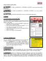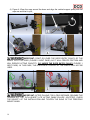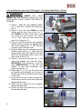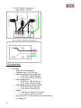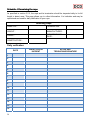
1
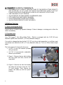
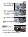
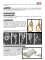
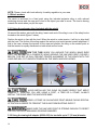
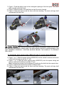
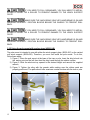
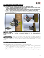
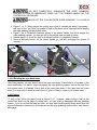
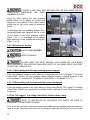
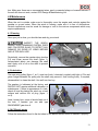
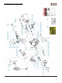
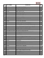
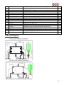
READ CAREFULLY BEFORE USE DCD Design & Manufacturing Ltd. & Manufacturing Ltd. TUF-Lugger™ Lite Lifting Cable Puller - Electric 41000-500 USER MANUAL Maximum pulling force (single line): 1800 lb (820 kg) Rated lifting capacity (single line): 550 lb (250 kg) © 2012 DCD Design & Manufacturing Ltd. & Manufacturing Ltd. - All Rights Reserved www.dcddesign.com English version Summary Introduction – p. 3 1.0 Safety guidelines – p. 3 1.1 Safety messages – p. 3 1.2 Labels – p. 4 1.2.1 Serial number and warning label – p. 4 1.2.2 Rope ‘DANGER’ label – p. 4 1.3 Safety information – p. 4 2.0 Before first use – p. 6 2.1 Upon receiving the winch – p. 6 2.2 Capstan drum – p. 6 3.0 Winch usage – p. 7 3.1 Working cycle – p. 8 3.2 Rope – p. 8 3.2.1 Rope type – p. 8 3.2.2 Rope maintenance – p. 8 3.2.3 At the end of the rope – p. 9 3.2.3.1 Recommendations – p. 9 3.2.3.1.1 When pulling – p. 9 3.2.3.1.2 When lifting – Rope with buried eyed splice – p. 9 3.3 Winch anchors – p. 10 3.3.1 Using the polyester sling – p. 10 3.3.2 Using the hitch plate winch anchor for tow balls – p. 10 3.3.3 Using the winch support plate with square tubing – p. 11 3.3.4 Using the winch support plate with Heck-Pack system for European balls – p. 12 3.3.5 Using the tree/pole mount with anchor strap – p. 12 3.3.5.1 With the winch support plate – p. 13 3.3.5.2 With the vertical pull winch support – p. 14 3.4 Moving a load – p. 15 3.4.1 Installing the rope on the PCT1800 Winch – p. 17 3.4.2 Lifting – p. 18 3.4.2.1 Load lifting chart – p. 18 3.4.2.2 Lifting operation – p. 18 3.4.2.3 Lowering a load – p. 19 3.4.2.4 Sending the rope back down – p. 20 3.4.3 Pulling – p. 20 3.4.3.1 Releasing the tension – p. 21 3.4.3.1.1 When pulling with the rope grabbing system engaged – p. 21 3.4.3.1.2 When pulling with the rope grabbing system disengaged – p. 21 3.5 If the TUF-Lugger™ Lite Lifting Cable Puller - Electric doesn’t work – p. 21 4.0 Maintenance – p. 22 4.1 Cleaning – p. 22 4.2 Lubrication – p. 22 4.3 AC Electric motor – p. 22 4.4 Storage – p. 23 5.0 Complementary information – p. 23 5.1 Accessories – p. 23 5.2 Serial number localization – p. 23 5.3 Warranty – p. 23 5.4 CE Declaration of conformity – p. 24 5.5 Electrical diagrams – p. 27 5.6 Technical data – p. 28 5.7 Periodical tests – p. 29 5.8 Manufacturer – p. 29 Schedule 1. Examining the rope – p. 30 2 Introduction DCD Design & Manufacturing Ltd. wishes to thank you for purchasing a TUF-Lugger™ Lite Lifting Cable Puller - Electric. This manual was written to help you make the best use of your new winch and to use it in the most secure way. READ IT CAREFULLY BEFORE USING THE WINCH. For any problems or questions please contact DCD Design & Manufacturing Ltd. directly. 1.0 Safety guidelines The TUF-Lugger™ Lite Lifting Cable Puller - Electric is designed for lifting objects at angles up to vertical. It is fitted with a rope grabbing system that can maintain the load in position and provide stop and go operation. THE ROPE GRABBING SYSTEM IS NOT DESIGNED TO STOP A FAST MOVING LOAD OR TO LIFT PEOPLE. The use of a lifting device implies serious risks of injuries, property damage or even death. DO NOT UNDERESTIMATE ITS POTENTIAL DANGER. WHEN LIFTING, NEVER GO OVER THE RATED LIFTING CAPACITY (550 lb (250 kg)) SINGLE LINE. WHEN LIFTING, NEVER BYPASS THE ROPE GRABBING SYSTEM. NEVER SHOCKLOAD THE SYSTEM. NEVER OPERATE THE WINCH WITHOUT PROPER TRAINING AND SUPERVISION. REMEMBER THE FIRST CAUSE OF ACCIDENT IS HUMAN ERROR. MAKE SURE EVERY PERSON HAS RECEIVED THE APPROPRIATE TRAINING FOR THE JOB. THE MANUFACTURER IS NOT RESPONSIBLE FOR DAMAGE CAUSED BY NEGLECTING TO FOLLOW THE GUIDELINES AND BY NEGLECTING TO FOLLOW SAFETY REGULATIONS. In particular, the USER has the obligation to verify: a) If the electrical receptacle is equipped with a ground compatible with the connector; b) If the electrical system is adequate; c) The implementation of safety measures to prevent loads from falling. 1.1 Safety messages Your safety and the safety of others are very important. You will find important safety messages in this manual. READ THEM CAREFULLY. These security messages are warning you of potential injuries to either you or others. Every safety message is preceded by a warning symbol DANGER, WARNING or CAUTION. and one of the following terms: 3 These indicator words mean: You WILL be MORTALLY or SEVERELY INJURED if you do not follow these instructions. You COULD be MORTALLY or SEVERELY INJURED if you do not follow these instructions. You COULD be INJURED if you do not follow these instructions. 1.2 Labels 1.2.1 Serial number and warning label The serial number and warning label is positioned on the right side of the winch housing. Read the meaning of all four icons (figure 1 to the right): 1. Read this instruction manual and Baldor engine user’s manual prior to using the winch. 2. Only use low-stretch rope. Minimum diameter: 1/2” (12 mm). Maximum diameter: 1/2” (13 mm). 3. Never place your hands near the moving parts while the engine is running. 4. Never use the winch for lifting people. 1.2.2 Rope ‘DANGER’ label The rope ‘DANGER’ label is positioned on the top of the winch housing. The meaning of the icon in figure 1 to the right is: 1. It is IMPERATIVE to use ONLY DCD Design & Manufacturing Ltd. double braided polyester rope 1/2” (12-13 mm) with buried eyed splice and a minimal breaking strength of 6945 lb (3150 kg). 1.3 Safety information DO NOT LET CHILDREN USE THE TUF-LUGGER™ LITE LIFTING CABLE PULLER - ELECTRIC. KEEP CHILDREN AND ANIMALS AWAY FROM THE WORK AREA. NEVER LET SOMEONE WITHOUT TRAINING USE THE TUF-LUGGER™ LITE LIFTING CABLE PULLER - ELECTRIC. MAKE SURE THE USER KNOWS ABOUT THE SAFETY AND USAGE PROCEDURES AND HAS READ THIS MANUAL AND THE BALDOR MOTOR LEAFLET. THE OPERATOR SHOULD BE ABLE TO OPERATE A LIFTING DEVICE 4 AND BE AWARE OF ALL ASPECTS OF SUCH OPERATIONS. HE SHOULD ALSO BE AWARE OF LOCAL REGULATION. INFORM ALL USERS OF THE SAFETY GUIDELINES AND USAGE PROCEDURES. FAMILIARIZE YOURSELF WITH THE PRODUCT AND THE SAFETY GUIDELINES BEFORE WORKING WITH THIS WINCH. MAKE SURE THAT YOUR CLOTHES ARE NOT GOING TO GET CAUGHT INTO THE WINCH MOBILE PARTS. USE ONLY 1/2” (12-13 MM) DIAMETER DOUBLE BRAID DCD DESIGN & MANUFACTURING LTD. POLYESTER ROPE WITH THIS WINCH. ALWAYS USE THE TUF-LUGGER™ LITE LIFTING CABLE PULLER ELECTRIC HORIZONTALLY, USING A PULLEY OR THE VERTICAL PULL WINCH SUPPORT TO REDIRECT THE ROPE VERTICALLY. REPLACE ANY SAFETY LABELS THAT ARE DAMAGED, ILLEGIBLE OR MISSING. NEVER PUT YOUR HANDS ON THE CAPSTAN DRUM, THE ROPE GRABBING SYSTEM, THE ROPE ENTRY PULLEY OR NEAR THE ROPE GUIDE WHEN THE MOTOR IS CONNECTED TO POWER SOURCE. ALWAYS KEEP BYSTANDERS OUTSIDE THE WORKING AREA. NEVER PULL ROLLING OBJECTS THAT MIGHT ROLL OUT OF YOUR CONTROL. NEVER TRY TO MOVE FIXED OR OBSTRUCTED LOADS. AVOID EXCESSIVE INCHING (E.G. GIVING SHORT PULSES TO THE MOTOR). ALWAYS INITIATE MOVEMENTS OF THE LOAD WITH THE LOWEST AVAILABLE SPEED. THE ROPE SHALL BE TIGHTENED AND SHALL NOT BE IN THE SLACK-CONDITION WHEN THE LOAD MOVEMENT BEGINS. SIDE-PULL OF LOAD IS NOT ALLOWED WITH THIS WINCH. KEEP IN MIND THAT YOUR SET-UP IS ONLY AS RESISTANT AS THE WEAKEST LINK. THIS IS WHY IT IS VERY IMPORTANT TO USE THE ADEQUATE ACCESSORIES IN ACCORDANCE WITH THE JOB TO BE DONE. IN THIS CASE (LIFTING), IT IS RECOMMENDED TO HAVE A 10 TO 1 SAFETY FACTOR FOR ALL ACCESSORIES. 5 IT IS STRICTLY FORBIDDEN TO: LIFT LOADS WITH A WEIGHT GREATER THAN TO THE RATED LIFTING CAPACITY (550 LB (250 KG); TO LIFT LOADS THAT IMPAIR THE OPERATOR’S VISIBILITY OR THAT COULD COLLIDE WITH OTHER MOVING LOADS OR WITH ADJACENT STRUCTURES; USE THE WINCH TO LIFT PEOPLE; ALLOW PEOPLE TO PASS UNDER A SUSPENDED LOAD; LIFT LOADS THAT ARE POORLY SLINGED; LEAVE SUSPENDED LOADS UNATTENDED; ALLOW OTHER PEOPLE TO USE THE WINCH. 2.0 Before first use 2.1 Upon receiving the winch Inspect the box to detect any apparent damage. If there is damage or missing parts, inform the carrier immediately. 2.2 Capstan drum Your TUF-Lugger™ Lite Lifting Cable Puller - Electric is equipped with the 3-3/8” (85 mm) diameter capstan drum and the 5” (127 mm) diameter safety lip. If you wish to change the drum for the 2-1/4” (57 mm) drum (sold separately), you will also need to purchase and install the 4-5/8” (117 mm) diameter safety lip. To do so, follow these simple steps: The tools required to change the drum are: A 5/32” (4 mm) hex wrench (included with your winch). An 7/16” (11 mm) wrench or adjustable wrench (not included). 1) Figure 1: Remove the two bolts holding the rope guide and then, remove the rope guide; 2) Figure 2: Remove the hex bolt holding the safety lip and drum using the 7/16” (11 mm) wrench. Then, remove the washer, the safety lip and the spacer bushing; 6 3) Figure 3: Remove the drum from the shaft. If necessary, you may push it forward with two screwdrivers. Make sure that the shaft key stays in place. 4) Figure 4: Insert the 2-1/4” (57 mm) drum on the winch shaft. Insert the washer, the 4-5/8” (117 mm) safety lip and the spacer bushing on the hex bolt and insert this assembly in the hole of the shaft. Then, tighten the hex bolt with the 7/16” (11 mm) wrench; 5) Figure 5: Insert the new rope guide in position and tighten it using the two (2) bolts. IMPORTANT: Make sure that the rope guide is not in contact with the capstan drum. 3.0 Winch usage MOST WINCHING SITUATIONS PRESENT POTENTIAL DANGERS! The winch must be plugged into a grounded plug. The use of an extension cord can cause a loss of power at full capacity. As listed on the product label (figure 1), make sure the voltage and current type are respected. Units 115V-60hz require 20 amps while the units 220V-50hz require 10 amps. 7 3.1 Working cycle This TUF-Lugger™ Lite Lifting Cable Puller - Electric is designed for intermittent use. The engine manufacturer recommends an engine duty cycle of 25%. So, to get a maximum lifetime out of the engine, it should only be used for fifteen (15) minutes period every hour. This data varies depending on the loads pulled or lifted. Light loads can be lifted or pulled continuously without affecting the life of the engine. Continuous pulls are however less damageable for the motor than frequents stop and go. 3.2 Rope STAY OUT OF THE WINCH LINE’S PATH. 3.2.1 Rope type USE ONLY LOW STRETCH 1/2” (12-13 MM) DIAMETER DCD DESIGN & MANUFACTURING LTD. DOUBLE BRAIDED POLYESTER ROPE WITH A MINIMAL BREAKING POINT OF 6945 LB (3150 KG) WITH THIS WINCH. PLEASE CONTACT US FOR OTHER ROPE TYPE’S SUITABILITY. DO NOT USE 3-STRAND POLYPROPYLENE YELLOW ROPE! Polypropylene and polyethylene ropes are dangerous for winching because of their great elasticity and low melt point. Make sure the rope is not damaged and that it offers an adequate resistance to pull the load. STRETCH EQUALS DANGER! A stretched rope can recoil and cause serious burns as the rope leaves your hand. All ropes stretch: a longer one more than a shorter one. The more you pull, the more it stretches. A stretched rope can also move the load in an unpredictable or dangerous way. A stretched rope can recoil and bring your hand towards the winch causing severe injuries. NEVER WRAP THE ROPE AROUND YOUR HAND. ALWAYS WEAR GLOVES. 3.2.2 Rope maintenance The rope and its ends should be inspected regularly to detect wear. Please refer to CI 2001 Document - FIBER ROPE INSPECTION AND RETIREMENT CRITERIA from the Cordage Institute available at www.ropecord.com for the procedure and criteria of scrapping the rope. 8 You will find a chart located at the end of this manual to better help you register your observations. IF YOUR ROPE IS DIRTY, WASH IT. DIRTY ROPES DETERIORATE FASTER AND CAUSE PREMATURE WEAR OF THE PARTS IN CONTACT WITH THE ROPE SUCH AS THE CAPSTAN DRUM AND ROPE GUIDE. 3.2.3 At the end of the rope 3.2.3.1 Recommendations Since the TUF-Lugger™ Lite Lifting Cable Puller - Electric can be used for pulling and lifting, there are some guidelines to follow: 3.2.3.2.1 When pulling For pulling loads, you have to attach the load to the end of the rope. Even if a simple knot can do the job, we recommend the installation of a hook with the bowline knot (figure 1 on the right) because it can be easily undone if you need to change the hook. Moreover, it retains about 70% of the rope’s capacity while most knots will reduce it by more than 50%. Even better, the double bowline knot (figure 2 below) will keep about 75% of your rope’s capacity. 3.2.3.1.2 When lifting - Rope with buried eyed splice For lifting, again, you have to attach the load to the end of the rope. Even if you believe that a bowline knot could do the job, it is STRONGLY RECOMMENDED to use the DCD Design & Manufacturing Ltd. rope with buried eyed splice. The installation of a hook with a strong enough safety factor carabiner or shackle to the rope will help prevent any problems that might occur in case of knot failure. 9 NOTE: Please, check with local authority for safety regulation in your area. 3.3 Winch anchors The winch is anchored to a fixed point using the included polyester sling or with optional anchoring devices and the rope end is tied to the object you want to move. The load is moving towards the winch when you pull the rope. 3.3.1 Using the polyester sling (included with the winch) Go around the anchor point with the sling. Insert each end of the sling in one of the safety hooks located on the winch (figure 1 below). Position the winch in line with the load. When the winch is under tension, it will try to align itself with the load. The friction of the sling against the anchor point could prevent correct alignment. If that is the case, release the tension on the rope and position the sling on the anchor point so that the tension is equally distributed on both winch anchor hooks. DON’T DO THIS! WHEN YOU ANCHOR THE WINCH, MAKE SURE THAT YOU DO NOT DO A COMPLETE WRAP AROUND THE ANCHOR POINT (FIGURE 2 BELOW). THIS SET-UP WILL PREVENT PROPER ALIGNMENT OF THE WINCH WITH THE LOAD AND WILL PUT UNEVEN TENSION ON THE WINCH ANCHOR HOOKS. AVOID INSTALLING THE SLING ON SHARP EDGES THAT MIGHT DAMAGE IT. WHETHER YOU ARE USING A POST, A TREE OR A STUMP, ALWAYS INSTALL THE SLING NEAR THE ANCHOR’S BASE. USING A STUMP AS AN ANCHOR POINT MEANS PAYING SPECIAL ATTENTION IN ORDER TO PREVENT THE SLING FROM SLIPPING OVER IT. MAKE SURE THE ANCHOR POINT IS STRONG ENOUGH TO RESIST THE PULL WITHOUT BREAKING OR BEING DAMAGED. 3.3.2 Using the towing ball adapter (42200-030) for tow balls up to 2” (50 mm) diameter 10 1) Figure 1: Push the safety hooks in the rectangular openings of the hitch plate. The rubber plate must be under the winch; 2) Figure 2: Slide the plate on the ball hitch and pull the winch forward; 3) Figure 3: Wrap the rope around the drum and start winching. The winch will align itself automatically with the load. USE THE HITCH PLATE ONLY WITH CATEGORY II BALL HITCH (3300 LB (1500 KG)) OR HIGHER. MAKE SURE THE ANCHORING VEHICLE’S HAND BRAKE IS ON AND WORKING PROPERLY. POSITION BLOCKS BEHIND THE WHEELS TO PREVENT ROLL BACK. 3.3.3 Using the winch support plate (42200-010) with 2” square tubing (42200-020) 1) Figure 1, no. 1: Slide the square tubing (42200-020) into the vehicle’s receiver and secure it with both the hitch pin and the ‘’R’’ pin; 2) Figure 1, no. 2: Slide the winch support plate (42200-010) onto the square tubing and secure it with both the hitch pin and the ‘’R’’ pin; Note: Its lateral movement can be adjusted by positioning the bolts into the square holes; 3) Figure 2: Attach the winch anchor hooks to the eye bolts; 4) Figure 2: Wrap the rope around the drum and start winching. The winch will align itself automatically with the load. 11 IF YOU NEED TO PULL DOWNWARD, YOU WILL NEED TO INSTALL EITHER A PULLEY OR A ROLLER TO PREVENT DAMAGE TO THE WINCH SUPPORT PLATE. MAKE SURE THE ANCHORING VEHICLE’S HAND BRAKE IS ON AND WORKING PROPERLY. POSITION BLOCKS BEHIND THE WHEELS TO PREVENT ROLL BACK. IF YOU NEED TO PULL DOWNWARD, YOU WILL NEED TO INSTALL EITHER A PULLEY OR A ROLLER TO PREVENT DAMAGE TO THE WINCH SUPPORT PLATE. MAKE SURE THE ANCHORING VEHICLE’S HAND BRAKE IS ON AND WORKING PROPERLY. POSITION BLOCKS BEHIND THE WHEELS TO PREVENT ROLL BACK. 3.3.5 Using the pole mount with anchor strap (42200-040) The pole mount is intended to use with either the winch support plate (42200-010) or the vertical pull winch support (42200-050). Therefore, you must first install the pole mount. To do this, follow these steps: 1) Figure 1: Place the pole mount at the base of the tree or pole. Insert the sling’s hook into the anchor point on the left; then feed the sling’s end through the ratchet system; 2) Figure 2: Slide the whole set-up upward to the desired height and remove the supplied wrench; 3) Figure 3: Tighten the sling with the wrench while making sure the rubber pads are properly positioned. The pads should offer maximum contact surface with the tree or pole. 12 3.3.5.1 With the winch support plate (42200-010) After the installation of the tree/pole mount (section 3.3.5), follow these steps: 1) Figure 1: Insert the winch support plate onto the square tubing of the pole mount (42200040) and fasten it down with the hitch pin and ‘’R’’ pin; Note: Its lateral movement can be adjusted by positioning the bolts into the square holes; 2) Figure 2: Attach the winch anchor hooks to the eye bolts of the winch support plate; 3) Figure 3: Wrap the rope around the drum and start winching. The winch will align itself automatically with the load. IF YOU NEED TO PULL DOWNWARD, YOU WILL NEED TO INSTALL EITHER A PULLEY OR A ROLLER TO PREVENT DAMAGE TO THE WINCH SUPPORT PLATE. AFTER PULLING FOR A FEW SECONDS WITH THE TREE/POLE MOUNT, RELEASE THE TENSION OFF THE TUF-LUGGER™ LITE LIFTING CABLE PULLER - ELECTRIC. CHECK THE SOLIDITY OF THE INSTALLATION AND TIGHTEN THE SLING AGAIN. 3.3.5.2 With the vertical pull winch support (42200-050) After the installation of the pole mount (section 3.3.5), follow these steps: 1) Figure 1: Insert the vertical pull winch support onto the square tubing of the pole mount (42200-040), align the holes and insert the pulley; 2) Figure 2: Tighten the nut with your fingers until it touches the support. Then reinforce it with the ‘’R’’ pin; 3) Figure 3: Attach the winch anchor hooks to the eye bolts of the vertical pull winch support; 13 4) Figure 4: Wrap the rope around the drum and align the vertical support pulley with the rope axe and start to pull; IMPORTANT: DON’T GO OVER THE ROPE ENTRY PULLEY OF THE WINCH WITH THE ROPE (FIGURE 2 NEXT PAGE) AS IT WILL CREATE FRICTION AND WILL REDUCE LIFTING CAPACITY. GO UNDER THE ROPE ENTRY PULLEY (FIGURE 1 NEXT PAGE). IN THIS CASE, THE ROPE ENTRY PULLEY OF THE WINCH WILL NOT BE USED. IMPORTANT: AFTER PULLING FOR A FEW SECONDS, RELEASE THE TENSION OFF THE TUF-LUGGER™ LITE LIFTING CABLE PULLER - ELECTRIC. CHECK THE SOLIDITY OF THE INSTALLATION AND TIGHTEN THE SLING OF THE TREE/POLE MOUNT AGAIN. 14 3.4 Moving a load USING COMMON SENSE WHILE MOVING A LOAD IS THE KEY TO A SECURE WINCH USAGE. The great variety of situations encountered when winching prevents us from providing specific instructions; however you need to consider the following points: CHECK WINCH POSITION, ROPE CONDITION, SOLIDITY OF THE ANCHOR POINT, KNOTS, CARABINERS OR SHACKLES IN ORDER TO PREVENT INJURIES OR MATERIAL DAMAGE. INSTALL THE ROPE IN SUCH A WAY THAT IT DOES NOT RUB AGAINST OTHER OBJECTS OR THROUGH AN OBSTRUCTION. GENERALLY, IF THE ROPE TOUCHES AN OBJECT, YOUR INSTALLATION IS INCORRECT. NEVER PUT YOUR HANDS ON THE CAPSTAN DRUM, THE ROPE GRABBING SYSTEM, THE ROPE GUIDE OR THE ROPE ENTRY PULLEY WHEN THE ENGINE IS RUNNING. LOOK AT YOUR SET-UP TO MAKE SURE THAT THE WINCH ANCHORS AND THE ROPE ENTRY PULLEY ARE ALIGNED WITH THE ROPE. WHILE WINCHING, POSITION YOURSELF AWAY FROM THE WINCH IN ORDER TO SEE BOTH THE WINCH AND THE LOAD. PULL HORIZONTALLY ON THE ROPE. THE TENSION YOU EXERT ON THE ROPE WILL KEEP THE WINCH LEVELED. DO NOT WRAP THE ROPE AROUND YOUR HANDS OR YOUR BODY! ALSO BEWARE OF THE ROPE ACCUMULATING NEXT TO YOU; MAKE SURE YOUR FEET DO NOT GET TANGLED IN IT. CAREFULLY WATCH THE CAPSTAN DRUM DURING THE OPERATION AND MAKE SURE THE ROPE DOES NOT CROSS OVER ON IT. IF IT HAPPENS, RELEASE THE TENSION ON THE ROPE AND STOP THE ENGINE WHILE UNDOING THE CROSS OVER. DO NOT PULL A LOAD DIRECTLY TOWARD THE WINCH IN A DOWNWARD SLOPE SINCE IT COULD SLIDE WITHOUT YOU BEING ABLE TO STOP IT. IN THAT SITUATION, USE A PULLEY AT THE BOTTOM OF THE HILL AND POSITION THE WINCH OUTSIDE OF THE LOAD’S PATH. 15 3.4.1 Installing the rope on the TUF-Lugger™ Lite Lifting Cable Puller - Electric NEVER PUT YOUR HANDS ON THE CAPSTAN DRUM OR THE ROPE ENTRY PULLEY WHEN THE WINCH IS RUNNING. 1) Figure 1: Open the rope grabbing system (no. 1) and lock in place with spring pin (no.2); 2) Figure 2: Run the rope OVER the rope keeper and the rope entry pulley (no. 1) and UNDER the drum (except when using the vertical pull winch support (see section 3.3.5.2). Then, wrap the rope around the drum 3 or 4 turns (no. 2); 3) Figure 3: Insert the rope into rope grabbing system device by pulling the spring-loaded cam lever upwards (no. 1). This will give enough room to insert the rope. 4) Figure 4: Make sure the rope goes over the stainless steel knob (no. 1). Then, push the spring-loaded cam back against the rope which will automatically hold a load if the rope end is let go (no. 2). 5) Figure 5: As you pull the rope (no. 1), the motor will engage and load will move. IMPORTANT: It is necessary to pull the rope HORIZONTALLY to get the load started. To stop load movement, stop pulling on rope (no. 2). 6) Stand about 3’ (1 m) from the winch and pull gently and horizontally on the rope to get the slack until you feel the tension rising on the rope; 7) Look at your set-up to make sure that the winch anchor and the rope entry pulley are aligned with the rope; 8) Check that the rope does not rub against objects along the path; 9) Pull on the rope, the power will go up and the winching will start. 16 3.4.2 Lifting 3.4.2.1 Load lifting chart BEFORE ATTEMPTING TO LIFT A LOAD, IT IS IMPERATIVE TO EVALUATE ITS APPROXIMATE WEIGHT. When lifting a load, you may figure the minimal number of wraps required on the capstan drum in order to move the load. Below is a chart showing the number of turns to do on the drum in accordance with the weight of the load. This chart is designed to help figure out the number of wraps you need to lift a load and also allow its lowering. The friction on the capstan drum is relative to the size of the drum installed, the number of wraps and the load weight, therefore too many wraps may prevent a load to lower. IMPORTANT NOTE: IF THE MOTOR STALLS WHILE LIFTING A LOAD, YOU HAVE EXCEEDED THE RATED LIFTING CAPACITY. THEREFORE, YOU MUST LOWER THE LOAD TO RELEASE THE TENSION ON THE ROPE AND INSTALL A BLOCK AND TACKLE DEVICE TO INCREASE THE LIFTING CAPACITY BEFORE RESTARTING TO PULL. DO NOT START UNDER TENSION OR YOU MAY DAMAGE THE MOTOR. Weight Number of turns on the drum Pounds Kilograms From 1 2 3 2 lb 177 lb 4 375 lb To From Never make only one turn 176 lb 1 kg 374 lb 81 kg 550 lb 171 kg To 80 kg 170 kg 250 kg 3.4.2.2 Lifting operation ALWAYS WEAR GLOVES. To lift a load, you will need to decide which anchoring accessories you will use. Refer to section 3.3 to decide. KEEP IN MIND THAT YOUR SET-UP IS ONLY AS RESISTANT AS THE WEAKEST LINK. THIS IS WHY IT IS VERY IMPORTANT TO USE THE ADEQUATE ACCESSORIES IN ACCORDANCE WITH THE JOB TO BE DONE. IN THIS CASE (LIFTING), IT IS RECOMMENDED TO HAVE A 10 TO 1 SAFETY FACTOR FOR ALL ACCESSORIES. Refer to the chart in section 3.4.2.1 for the correct number of wraps of rope to use. 17 3.4.2.3 Lowering a load ALWAYS WEAR GLOVES. YOUR TUF-LUGGER™ LITE LIFTING CABLE PULLER - ELECTRIC IS EQUIPPED WITH A ROPE GRABBING SYSTEM. THIS SYSTEM IS NOT DESIGNED TO STOP FAST MOVING LOADS. DAMAGE CAN OCCUR TO THE ROPE AND/OR THE ROPE GRABBING SYSTEM WHEN SHOCK LOADED, AND POSSIBLY LEAD TO CATASTROPHIC FAILURE. DO NOT WRAP THE ROPE AROUND YOUR HANDS OR YOUR BODY! ALSO BEWARE OF THE ROPE ACCUMULATING NEXT TO YOU; MAKE SURE YOUR FEET DO NOT GET TANGLED IN IT. THE TUF-LUGGER™ LITE LIFTING CABLE PULLER - ELECTRIC IS NOT DESIGNED FOR LOWERING HEAVY LOADS OVER LONG DISTANCES. FRICTION OF THE ROPE ON THE CAPSTAN DRUM WILL GENERATE HEAT THAT COULD DETERIORATE OR EVEN MELT THE ROPE. YOU MAY WANT TO RUN SOME TESTS IN ORDER TO EXPERIMENT. YOU CAN ALSO USE PULLEY BLOCKS ON THE LOAD TO REDUCE FRICTION ON THE DRUM. AFTER EACH LOWERING OPERATION, IT IS IMPERATIVE TO CHECK ROPE CONDITION. NEVER GO OVER THE RATED LIFTING CAPACITY (550 LB (250 KG)) SINGLE LINE. NEVER BYPASS THE ROPE GRABBING SYSTEM. NEVER SHOCKLOAD THE SYSTEM. BEWARE OF ROPE SNARLS WHILE LOWERING. IF ROPE GETS TANGLED, PULL ON ROPE, WHICH WILL START THE MOTOR, UNTIL CLEARED. DO NOT TOUCH THE CAPSTAN DRUM IMMEDIATELY AFTER OPERATION AS IT WILL GET HOT AND BURN BARE SKIN. When you stop lifting with the TUF-Lugger™ Lite Lifting Cable Puller - Electric, the rope grabbing system engages, therefore, holds a load in position and keeps the rope under tension. To release it, follow these steps: 1. Figure 1, no. 1: Pull horizontally (and gently) on the pulling rope to engage the motor, this will release the tension applied by the rope grabbing system on the pulling rope; 2. Figure 1, no. 2: Pull gently on the rubber handle of the rope attached to the rope grabbing system; this will disengage the system; 18 DO NOT COMPLETELY DISENGAGE THE ROPE GRABBING SYSTEM, IN CASE OF EMERGENCY, SIMPLY LET THE RUBBER HANDLE GO, THE SYSTEM WILL RE-ENGAGE. NEVER LET THE PULLING ROPE SLIDE SUDDENLY IF A LOAD IS SUSPENDED. 3. Figure 1, no. 3: Slowly payout the pulling rope (push it towards the winch if necessary this may occur if you have four wraps of rope on the drum and a light load) while keeping the rope grabbing system slightly open; 4. Figure 1, no. 4: Release the tension applied to the rubber handle, this will re-engage the rope grabbing system. You can now let go the pulling rope and grab it further; 5. Repeat steps 1 to 4 until the load is at desired position or completely lowered; 6. Once at desired position, let the rubber handle go, this will re-engage the system (if needed); 3.4.2.4 Sending the rope back down After lifting objects, you may want to send the rope back down. Since there is no reverse on the winch and friction is in cause, simply disengage the rope grabbing system, remove the rope from the capstan drum to eliminate friction and let the rope back down. If the rope does not come down, you may have to attach a small rope to it (prior to lifting) in order to pull it back down. 3.4.3 Pulling To pull a load, follow the steps found in section 3.4.1. However, when pulling a load on the ground that does not risk falling or rolling back, you may want to disengage the rope grabbing system. If you do not and the load get stuck, you may have trouble getting some slack since the rope will already be stretched to its maximum and the rope grabbing system will be very hard to disengage. 19 IF THERE IS ANY RISK THE LOAD MAY FALL OR ROLL BACK, DO NOT COMPLETELY DISENGAGE THE ROPE GRABBING SYSTEM. Using the winch without the rope grabbing system allows you to release the tension and benefit from the elasticity of the rope to restart pulling and let the motor reach its maximum power. To disengage the rope grabbing system, open the spring-loaded cam upwards and let it rest on the frame of the rope grabbing system (figure 1, no. 1). To re-engage it, lift it upward again and bring it back towards the pulling rope (figure 1, no. 2). 3.4.3.1 Releasing the tension ALWAYS WEAR GLOVES. STRETCH EQUALS DANGER! DO NOT WRAP THE ROPE AROUND YOUR HANDS OR YOUR BODY! ALSO BEWARE OF THE ROPE ACCUMULATING NEXT TO YOU; MAKE SURE YOUR FEET DO NOT GET TANGLED IN IT. 3.4.3.1.1 When pulling with the rope grabbing system engaged If the rope grabbing system is used, when you stop pulling with the TUF-Lugger™ Lite Lifting Cable Puller - Electric, the rope grabbing system engages, therefore, applies pressure on the rope and keeps it under tension. To release it, follow steps 1 to 6 of section 3.4.2.3). 3.4.3.1.2 When pulling with the rope grabbing system disengaged If the rope grabbing system is not used, when you stop pulling with the TUF-Lugger™ Lite Lifting Cable Puller - Electric, you simply have to release tension gradually to lower the winch gently to the ground. 3.5 If the TUF-Lugger™ Lite Lifting Cable Puller - Electric doesn’t work PRIOR TO INSPECTING OR REPAIRING THE WINCH, BE SURE TO DISCONNECT FROM POWER SOURCE. If the winch does not work, check the power source. Make sure the voltage and/or the frequency used is correct. Disconnect the wire from the electrical outlet and remove the lid of the control 20 box. Make sure there are no unconnected wires, poorly connected relays or loosened screws. If the unit still does not work, contact DCD Design & Manufacturing Ltd. 4.0 Maintenance When the unit is outside, make sure to thoroughly cover the engine and controls against the weather or ground water. When the winch is running, make sure it is free of obstructions. Periodic inspections must be made for damage or cuts to the various components which may require replacement. 4.1 Cleaning Once your job is done, you should clean and dry your winch. INSPECT THE WINCH, HOOKS, ROPE GRABBING SYSTEM, ROPE AND POLYESTER SLING TO DETECT ANY DAMAGE OR SIGNS OF WEAR BEFORE AND AFTER EACH USE. Periodically, remove the capstan drum (section 2.2) and clean around the shaft (figure 1). Accumulated debris can damage the shaft seal. Apply a bit of oil on the shaft to prevent corrosion. 4.2 Lubrication The rope entry pulley (figure 1, no 1) must turn freely. Lubricate it regularly with light oil. Dirt and grime lodged between the pulley and the shaft may prevent it from turning freely. If required, disassemble it to clean the shaft. Use an 8 mm hex key. The gearbox is lubricated at the factory and SHOULD NOT require additional lubrication or maintenance. If there is appearance of a leak, check oil level by placing the winch on a level surface and remove the oil plug (figure 1, no.2). Lean it toward you; some oil should leak out of the hole. If needed, you can add type SAE80W90EP gear box oil. 4.3 AC Electric motor Follow the instructions found in the fact sheet of the Baldor electric motor to maintain it properly. 21 4.4 Storage Always store your TUF-Lugger™ Lite Lifting Cable Puller - Electric seated on its guard plate and in a dry environment. 5.0 Complementary information 5.1 Accessories A complete line of accessories is available. Simply visit www.tufluggerlite.com 5.2 Serial number localization The winch serial number is indicated on the serial number and warning label located on the right side of the winch housing and is also engraved on the cover of the winch, to the left of the capstan drum. 5.3 Warranty DCD Design & Manufacturing Ltd. products are warranted against defects in materials and workmanship while owned by the ''original purchaser''. The ''original purchaser'' is defined as the party or entity which purchases the winch and/or accessories from an authorized DCD Design & Manufacturing Ltd. retailer as shown by the original invoice. The warranty ownership is transferable, provided the end-user has a copy of the original purchaser’s invoice. This warranty does not apply to ''wear parts'' defined as being in contact with the rope while winching. The TUF-Lugger™ Lite Lifting Cable Puller - Electric is covered as follow: Winch components: o Private use: Two (2) year warranty (service by DCD Design & Manufacturing Ltd. and/or its retailers); o Commercial use: One (1) year warranty (service by DCD Design & Manufacturing Ltd. and/or its retailers); Motor: The Baldor motor is warranted by Baldor and the duration varies according to country and usage. All Baldor service centers can repair the winch motor under warranty. Hang on to your proof of purchase (invoice with serial number). It will be used to establish the beginning of the warranty period. DCD Design & Manufacturing Ltd. will replace or repair, at its option, any defective product. All other TUF-Lugger™ Lite accessories are covered by a complete one (1) year warranty. Please refer to the DCD Design & Manufacturing Ltd. warranty policies on www.dcddesign.com if you have any questions. 22 5.4 Exploded view and parts list 23 ITEM NO. 1 2 3 4 5 6 7 8 9 10 13 14 15 16 17 18 19 20 21 23 24 25 26 26 27 28 29 30 31 32 33 34 38 39 40 41 41 42 43 44 45 46 46 47 48 24 PART NUMBER 31-0011 10-0102 42110-337 10-0043 31-0025 10-0106 31-0010 35-0004 10-0098 42430-020 31-0019 10-0073 10-0080 33-0004 42-0020 10-0116 31-0021 42-0010 42-0007 10-0114 10-0115 INCLUDED WITH 42-0022 42-0019 42-0022 44-0019 10-0094 33-0005 10-0067 43-0005 31-0020 10-0081 10-0086 35-0006 31-0023 10-0069 10-0068 32-0002 32-0003 10-0111 10-0112 43-0013 10-0103 10-0101 10-0119 DESCRIPTION HCS 1/4-20 X 2-1/4 - GR5 - ZN DRUM RETAINING WASHER SAFETY LIP FOR CAPSTAN DRUM 3-3/8” SPACER FOR SAFETY LIP BHCS 1/4-20 X 3/4 - SS ROPE GUIDE FOR CAPSTAN DRUM 85 MM HCS 1/2-13 X 6 - GR5 - ZN FLAT WASHER 1/2 - ZN BUSHING FOR SAFETY HOOK SAFETY HOOK 3/4 TON HCS 3/8-24 X 1 GR5 - ZN ADPATOR FOR HANDLE 41000-500-50Hz-P ELECTRIC BOX ELECTRIC BOX - MACHINED K-LOK 10-24 - ZN 2 POLES 240 VOLTS 50Hz CONTACTOR OR 60Hz ELECTRIC WIRE 14 AWG FOR CONTACTOR MACHINE SCREW 10-24 X 1/2 - ZN (PAN HEAD SQ. DR.) STRAIN RELIEF CONNECTOR 1/2 WITH NUT W/ TIGHTENIG RING 1/2in LIQUIDTIGHT STRAIN RELEF CORD CONNECTOR ELECTRIC CORD 14/3 AWG FROM MOTOR ELECTRIC CORD 14/3 AWG FOR SWITCH KEY FOR ELECTRIC MOTOR SHAFT ELECTRIC PLUG CEE 7/7 250V 16AMP GROUNDED BALDOR ELECTRIC MOTOR 50Hz 220V 3/4HP VINYL GRIP WINCH HANDLE NYLON LOCKNUT 1/2-13 - Zn COUPLING SHAFT FOR ELECTRIC MOTOR KEY FOR INPUT PINION MACHINE SCREW 10-24 X 1-3/4 - ZN (PAN HEAD SQ. DR.) LIMIT SWITCH INPUT PINION FLAT WASHER 1/4 - ZN BUTTON HEAD CAP SCREW 1/4-28 x 1/2 Gr5 - Zn GUARD PLATE PCT1800-50Hz GUARD PLATE PCT1800-60Hz HEX FLANGE SERRATED BOLT M6-1 X 12 MM - ZP SHCS M5-0.80 X 16 MM ON/OFF CABLE END HOLDER ON/OFF CABLE HOUSING FOR PCT1800-P KEY FOR CAPSTAN DRUMS 57 MM & 85 MM ROPE KEEPER ROPE ENTRY PULLEY SHOULDER BOLT 5/8 X 1-1/2 - ZN QTY 1 1 1 1 2 1 1 4 2 2 3 1 1 4 1 1 3 1 4 1 2 1 1 1 1 1 1 1 1 2 1 1 2 1 1 4 5 1 1 1 1 1 2 49 42100-337 CAPSTAN DRUM 3-3/8” 1 50 52 53 54 55 56 57 58 60 44-0001 UNIVERSAL SERIAL NUMBER & WARNING LABEL 1 44-0022 70-0006 31-0033 39-0014 70-0007 42110-225 42100-225 10-0100 ROPE DANGER LABEL ROPE GRABBING SYSTEM SHCS 5/16-18 X 1-3/4 - SS PULL PIN 1/4-20 ROPE GRABBING SYSTEM ATTACHMENT SAFETY LIP FOR CAPSTAN DRUM 2-1/4” CAPSTAN DRUM 2-1/4” ROPE GUIDE FOR CAPSTAN DRUM 2-1/4” 1 1 1 1 1 1 1 31-0015 HCS 3/8 X 1-1/4 - GR5 - ZN 2 42-0023 10-0072 10-0071 10-0077 10-0082 10-0113 WIRE CONNECTOR #8 TO #12 SUPPORT PLATE FOR ELECTRIC BOX 41000-500-50Hz SUPPORT PLATE FOR ELECTRIC BOX 41000-500-60Hz EYE CONNECTOR 12 GA (YELLOW) WIRE CONNECTOR 14 GA (BLUE) ON/OFF CABLE FOR PCT1800-P 3 1 1 2 1 5.5 Electrical diagrams 25 5.6 Technical data 26 41000-500: o Gear box: Aluminum alloy o Capstan drum: 3-3/8” (85 mm) o Maximum pulling force (single line): 3-3/8” drum: 1800 lb (820 kg) 2-1/4” drum: 2200 lb (1000 kg) o Rated pulling force: 3-3/8” drum: 1000 lb (455 kg) 2-1/4” drum: 1220 lb (555 kg) o Rated lifting capacity: 555 lb (250 kg) 3-3/8” drum: 550 lb (250 kg) 2-1/4” drum: 550 lb (250 kg) o Speed: 3-3/8” drum: 35 ft/min (10.5 m/min) 2-1/4” drum: 23 ft/min (7 m/min) o Duty cycle: 25% (15 min per hour is recommended) o I.P. Rating: 54 o Rope: Low stretch double braided polyester (not included) - Unlimited rope length Minimum diameter: 1/2” (12 mm) Maximum diameter: 1/2” (13 mm) 41000-500 Motor: o Motor: AC Electric Baldor TEFC 115/230 VAC - 1 ph - 3/4 HP o Unit weight (dry): 53 lb (24 kg) o Dimensions (overall): Length 19” (48 cm) - Width 15” (38 cm) - Height 14” (36 cm) 5.7 Periodical tests Some local regulations require that equipment used for lifting be tested regularly. Check with local authorities and contact your authorized dealer for DCD Design & Manufacturing Ltd. for testing procedures. 5.8 Manufacturer The TUF-Lugger™ Lite Lifting Cable Puller - Electric is manufactured for: DCD Design & Manufacturing Ltd. 180-6620 McMillan Way Richmond, BC, V6W 1J7, CANADA Phone: +1-604-232-4445 Toll free (Canada & USA): 1-888-794-8357 Fax: +1-604-232-4446 Email: [email protected] Web site: www.dcddesign.com 27 Schedule I. Examining the rope As specified in section 3.2.2, the rope and its termination should be inspected daily to its full length to detect wear. This page allows you to collect information. It is indicative and may be reproduced and used for daily verification of your rope. Winching Rope DIAMETER : TERMINATION : LENGHT : MANUFACTURER : FIBRES : COMMISSIONING DATE : CONSTRUCTION : Daily verification DATE 1 2 3 4 5 6 7 8 9 10 11 12 13 14 15 16 28 INSPECTION OR INCIDENT NOTES AND TECHNICIANS SIGNATURE 17 18 19 20 21 22 23 24 25 26 27 28 29 30 31 32 33 34 35 36 37 38 39 40 41 42 43 44 29